Simulation and optimization of a horizontal ammonia synthesis reactor using genetic algorithm

M. J. Azarhoosh*, F. Farivar and H. Ale Ebrahim
Chemical Engineering Department, Petrochemical Center of Excellence, Amirkabir University of Technology (Tehran Polytechnic), Tehran 15875-4413, Iran. E-mail: m.j.azarhoosh@aut.ac.ir; Fax: +98 66405847; Tel: +98 9387295609

Received 26th September 2013 , Accepted 22nd January 2014

First published on 23rd January 2014


Abstract

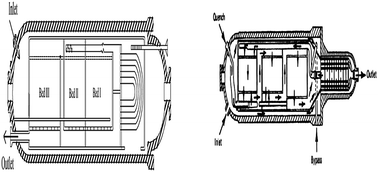
The synthesis of ammonia from nitrogen and hydrogen is one of the most important processes in petrochemical industry. In this study simulation and optimization of a horizontal ammonia synthesis reactor is presented in two cases: first, an intercooled horizontal ammonia synthesis reactor of the Khorasan petrochemical plant, second, a horizontal ammonia synthesis reactor with two quench flows. The one-dimensional heterogeneous mathematical model consists of two point boundary value differential equations for the catalyst pellets which were used in the simulations. Also, the effectiveness factor was calculated by both an empirical relation and considering the diffusion-reaction equations. The differential equations of boundary and initial value problems are solved with a combination of the Runge–Kutta method and an improved shooting method. The simulation was done for two cases. The first case is an intercooled horizontal ammonia converter, and the second one is a horizontal ammonia converter with two quench flows. Good agreement is achieved between simulated results, i.e., the outlet component mole fraction and temperature, and industrial data (Khorasan plant data and SRI report). Then the effect of parameters like inlet temperature, total feed flow rate, and operating pressure on ammonia production is studied. Finally, optimum solutions for the maximum mass flow rate production of ammonia are determined using a genetic algorithm (GA). The adjustable parameters are inlet temperature, total feed flow rate and operating pressure. The results of optimization show that a maximum ammonia mass flux of 52[thin space (1/6-em)]433 kg h−1 and 73[thin space (1/6-em)]979 kg h−1 was produced in both cases, respectively, in which the inlet temperature, feed flow rate, and operating pressure were, respectively, 524 °C, 217[thin space (1/6-em)]005 kg h−1 and 167 atm in the first case and 437 °C, 354[thin space (1/6-em)]986 kg h−1 and 237 atm in the second one.


1. Introduction

Ammonia is one of the most important petrochemical products manufactured worldwide. The largest fraction of ammonia is used for production of fertilizers like ammonium nitrate, ammonium phosphate, and urea.1 Moreover, ammonia is an essential material for producing other chemicals such as nitric acid, ethanol amines, and toluene diisocyanate.

The ammonia synthesis reactor is the heart of an ammonia production plant. Copious research on the mathematical modeling of ammonia synthesis reactors has been done.2–7 Many of these studies have shown that mathematical modeling is a convenient way to analyze and optimization of the reactor.6–11 In practice, a small improvement in the conversion degree considerably affects the overall economic balance of the ammonia production plant. Therefore, accurate modeling is essential for the analysis and design.

Ammonia synthesis is a straightforward reaction and there are no side reactions. The synthesis reaction based on the Haber–Bosh process takes place at high temperatures and pressures over a magnetic iron oxide, or recently, using Ru based catalysts.12 These reactors require a cooling system to achieve a high degree of conversion, because the reaction is highly exothermic. Based on the implemented cooling method, there are two types of converters for ammonia synthesis; tube-cooled converters and quench type converters.13

Many studies on the modeling and simulation of various configurations for an ammonia converter have been carried out. Annable is among the first researchers who studied the modeling of steady state ammonia converters.14 Baddour et al. developed a simple pseudo-homogeneous steady state model for Tennessee Valley Authority (TVA) type converters.15 Panahandeh et al. developed a two dimensional model for the axial-radial ammonia synthesis reactor.16 None of the above mentioned studies are about the horizontal ammonia converter. Dashti et al. recently simulated a horizontal ammonia converter with an internal heat exchanger.17 The density and viscosity have been assumed constant in the modeling; however, since the temperature and pressure vary along the converter, the density and viscosity of the gas mixture will change to a certain extent.

There are very few references that use evolutionary algorithm (EA) techniques in chemistry and catalysis which include the genetic algorithm (GA), evolutionary strategy (ES), genetic programming (GP), etc. Evolutionary strategy (ES) was used for selection and optimization of heterogeneous catalytic materials.18 Genetic programming has been employed very sparsely. Baumes et al.19,20 showed two examples of this very powerful technique. Genetic algorithms (GA) have been done by various groups such as Pereira et al.21 They reported a study on the effect of the genetic algorithm (GA) configurations on the performance of heterogeneous catalyst optimization. Also, Gobin et al.22,23 used a multi-objective experimental design of experiments based on a genetic algorithm to optimize the combinations and concentrations of solid catalyst systems. Moreover, genetic algorithm merges with a knowledge based system24 and has been boosted on a GPU hardware to solve a zeolite structure.25,26 In addition, GA has been used for crystallography and XRD measurements27,28 and as an active learning method for effective sampling.29

Although a number of papers on the production of ammonia are available, very few have tried to optimize the process conditions to get maximum benefit. In this study, an improved model for a horizontal ammonia synthesis reactor was developed in two cases. First, the intercooled horizontal ammonia synthesis reactor of the Khorasan petrochemical plant, and second, the horizontal ammonia synthesis reactor with two quench flows. The effect of density and viscosity change as well as pressure change along the bed length were considered in the model. Furthermore, the heat capacity of species was considered as a variable along the beds in order to increase accuracy. The effectiveness factor was calculated by both an empirical relation and a diffusion-reaction approach. The fourth-order Runge–Kutta method was used to solve the set of differential equations of the boundary and initial value problems. The modeling results were compared with some industrial data with good agreement. Then the effect of parameters like inlet temperature, pressure, and total mass flow rate on conversion was studied. Finally, the optimum conditions for maximum mass flow rate production of ammonia were determined by the genetic algorithm (GA). The adjustable parameters were inlet temperature, total feed flow rate, and operating pressure.

2. Horizontal converter description

Compared to the vertical converters, a horizontal converter containing three adiabatic catalytic beds has the character of a larger flow cross-section and a shorter flow length. On the other hand, small catalyst particles can be used to increase the internal surface, macro reaction rate and outlet ammonia concentration.30 Therefore the horizontal configuration overcomes some disadvantages of the vertical converters such as high pressure drop, large vessel diameter, and high catalyst volume.31 Furthermore, the catalyst bed is arranged in a basket that fits into a horizontal shell, so that catalyst loading and unloading is facilitated.30 This design has been developed by M. W. Kellogg, and it has been proven to be economical for industrial use.31 There are different types of such converters with various cooling methods and a different number of beds.32–34

2.1. First case

Fig. 1 shows the overall layout of an intercooled horizontal ammonia converter. The feed, after entering the reactor, passes through the shell of the internal heat exchanger where its temperature rises. When the gas passes the first bed and the reaction takes place, its temperature increases and it then enters the tubes of the heat exchanger to cool down. No specific operation is carried out between the second and third bed.
image file: c3ra45410j-f1.tif
Fig. 1 Horizontal intercooled ammonia converter.

2.2. Second case

The horizontal ammonia converter with two quench flows is illustrated in Fig. 2. The reactor inlet gas is divided into three parts: mainstream, first quench flow, and second quench flow. The mainstream passes through an empty space of beds and the reactor wall and goes to the internal heat exchanger where it is heated with the output product stream. In the heat exchanger, the gas preheats to about 400 °C and then enters the first bed. After passing through the first bed, the temperature is increased to about 496 °C. The output gas from the first bed is quenched with the first quench flow and consequently its temperature is decreased. After that, it is sent into the second bed. Similarly, the output gas from the second bed is mixed with the second quench flow and is entered to the third bed. Finally, the product gas from the third bed is directed out of the converter through the heat exchanger.
image file: c3ra45410j-f2.tif
Fig. 2 Horizontal ammonia converter with two quench flows.34

3. Mathematical model

The following assumptions have been considered in the mathematical modeling:

1 The model is heterogeneous and one-dimensional.

2 Heat and mass dispersions in the longitudinal direction are negligible.6

3 The reactor is operating at steady-state conditions.

4 The heat transfer resistance between the pellets and gas is negligible.6

3.1. Mass balance (bulk gas)

In a molar differential balance, nitrogen is considered as a reference component and gives a mass balance equation as:
 
image file: c3ra45410j-t1.tif(1)

3.2. Reaction rate

The modified Temkin equation was used to calculate the intrinsic rate of the reaction as follows:35
 
image file: c3ra45410j-t2.tif(2)
where α is a constant between 0.5 and 0.75.35 In this work, α = 0.5 was used. Ka was calculated as follows:6
 
image file: c3ra45410j-t3.tif(3)

In eqn (3), T represents the temperature in Kelvins. k2 was estimated by an Arrhenius relation as follows:7

 
image file: c3ra45410j-t4.tif(4)
where image file: c3ra45410j-t5.tif is the activation energy.35

Components activity can be defined as:

 
image file: c3ra45410j-t6.tif(5)
where fi is the reference fugacity and was assumed to be 101.325 kPa. Hence:
 
ai = fi = yiϕiP (6)

The fugacity coefficients of nitrogen, hydrogen, and ammonia can be determined from ref. 35 (Table 1).

Table 1 Fugacity coefficients of nitrogen, hydrogen and ammonia35
ϕN2 = 0.93431737 + 0.3101804 × 10⁻³T + 0.295896 × 10⁻³P − 0.2707279 × 10⁻⁶T2 + 0.477507 × 10⁻⁶P2
image file: c3ra45410j-t7.tif
ϕNH3 = 0.1438996 + 0.2028538 × 10⁻²T − 0.448762 × 10⁻³P − 0.1142945 × 10⁻⁵T2 + 0.2761216 × 10⁻⁶P


3.3. Energy balance

Using the energy balance for a differential element in the catalyst bed of the converter yields:
 
image file: c3ra45410j-t8.tif(10)
Cpmix is the specific heat for the gas mixture. Specific heat for pure components is a function of temperature and pressure that is given in Table 2.11
Table 2 Specific heats for pure components11
(Cp)H2 = 4.184(6.952 − 0.04576 × 10⁻²T + 0.09563 × 10⁻⁵T2 − 0.2079 × 10⁻⁹T3)
(Cp)N2 = 4.184(6.903 − 0.03753 × 10⁻²T + 0.1930 × 10⁻⁵T2 − 0.6861 × 10⁻⁹T3)
(Cp)NH3 = 4.184(6.5846 − 0.61251 × 10⁻²T + 0.23663 × 10⁻⁵T2 − 1.5981 × 10⁻⁹T3 + [96.1778 − 0.067571P + (−0.2225 + 1.6847 × 10⁻⁴P)T + (1.289 × 10⁻⁴ − 1.0095 × 10⁻⁷P)T2])
(Cp)CH4 = 4.184(4.750 + 1.200 × 10⁻²T + 0.3030 × 10⁻⁵T2 − 2.630 × 10⁻⁹T3)
(Cp)N2 = 4.184(4.9675)


It must be mentioned that the average specific heat of the reaction varies with the degree of conversion. Here, the heat of reaction was calculated from the following equation:36

 
ΔHr = 9723.24[−23[thin space (1/6-em)]840.57 + (P − 300.0)(1.08 + (P − 300.0)(0.01305 + (P − 300.0)(0.83502 × 10⁵ + (P − 300.0) × 0.65934 × 10−7))) + 4.5 × (1391.0 − T) (16)

3.4. Pressure drop

The pressure drop along the catalyst beds of the converter has been calculated by the Ergun equation for one-dimensional flow as follows:37
 
image file: c3ra45410j-t9.tif(17)

The density of the gas mixtures has been calculated by modification of the perfect gas law as follows:38

 
image file: c3ra45410j-t10.tif(18)

The viscosity of components was accurately corrected as a function of temperature:38

 
image file: c3ra45410j-t11.tif(19)
in which A, B, C, and D constants are available for about 1500 components in ref. 39. In order to predict the viscosity of gaseous mixtures, the Bromley and Wilke method was used.37 Here, the Stiel and Thodos method was used in order to correct it at high pressures.38

3.5. Effectiveness factor (η)

In this work, the effectiveness factor was calculated by two approaches, an empirical relation and also the diffusion-reaction model approach.40 The simulation results for both methods were compared along the reactor beds.
3.5.1. Empirical relation. The empirical relation for the effectiveness factor with respect to temperature and conversion has been developed by Dyson and Simon as follows:35
 
η = b0 + b1T + b2X + b3T2 + b4X2 + b5T3 + b6X3 (20)

In the above equation, X is the conversion of nitrogen, and bi are coefficients where their values for different operating pressures were presented in ref. 35. In this work, coefficients for 15[thin space (1/6-em)]000 kPa were used. The coefficients for this pressure are given in Table 3.

Table 3 Coefficients of empirical relation (20) for effectiveness factor calculation35
b0 b1 b2 b3 × 104 b4 b5 × 108 b6
−17.539096 0.07696844 6.900548 −1.08279 −26.4247 4.92765 38.9373


3.5.2. Diffusion and reaction approach. In this approach, the diffusion through catalyst pores was considered by a molar differential balance for component i inside the catalyst particle:
 
image file: c3ra45410j-t12.tif(21)
where γi is the stoichiometric coefficient of i'th component. After some straightforward manipulations, the equation will have the following dimensionless form:6
 
image file: c3ra45410j-t13.tif(22)

The boundary conditions are:

image file: c3ra45410j-t14.tif
where image file: c3ra45410j-t15.tif and C is the total concentration, defined as:
 
image file: c3ra45410j-t16.tif(23)

The effective diffusion coefficients are calculated with the relation given by Elnashaie and Elshishini:40

 
image file: c3ra45410j-t17.tif(24)

The Stefan–Maxwell equation for multi-component diffusion was used for computing the diffusion coefficients of the components:6

 
image file: c3ra45410j-t18.tif(25)
where
 
image file: c3ra45410j-t19.tif(26)

After calculation of the intraparticle concentration from eqn (22), the effectiveness factor can be computed as:41

 
image file: c3ra45410j-t20.tif(27)

4. Numerical solution algorithm

The first step to solve the model equations is to calculate the effectiveness factor at the entrance of the reactor. In the diffusion-reaction approach, the effectiveness factor can be obtained by solving the catalyst pellet equations. These equations are non-linear boundary value problems. There are several methods for solving eqn (22). The finite difference and orthogonal collocation methods convert the problem to a set of algebraic equations. When eqn (22) is nonlinear, the resulting set of equations is also nonlinear. The solution of nonlinear equations may not be unique and the generation of any solution may be difficult.42 A combination of fourth-order Runge–Kutta method with an improved shooting method was used to solve these sets of differential equations.42 The conventional shooting method converts the boundary value problem into an initial value problem. Starting with an assumed condition for the missing initial condition and improving it through iteration, the method tries to reach a solution that agrees with all the given boundary conditions. In the conventional forward shooting, integration of eqn (22) starts at w = 0 with image file: c3ra45410j-t21.tif and an assumed yi(0), the missing part in the problem. Unless the computed yi(1) with the Runge–Kutta method agrees with the boundary condition of yi(1) = yig, yi(0) is adjusted in an iterative procedure until the assumed yi(0) yields a solution that agrees with the boundary condition within a specified tolerance. The conventional shooting method can be applied to compute the effectiveness factors only when the concentration at the catalyst center is greater than zero, i.e., yi(0) > 0, because yi(0) = 0 always results in a trivial solution yi(w) = 0 in the method. Indeed, yi(0) = 0 can occur when the reaction order is less than one and the Thiele modulus is large. To overcome such limitations of the conventional shooting method, an improved shooting method is used. In this method, the reaction rate f(yi) is approximated as a linear function of the concentration yi in an interval of yi = 0 and yi = ψ, a sufficiently small number which was set as 10−9. This approximation prevented yi(0), however small, from becoming zero. The proposed shooting method with the approximation has been found to be robust and efficient in computing the effectiveness factors.42 Having the effectiveness factor, bulk phase mass and heat balance differential equations can be solved. This procedure should be repeated for each differential step to obtain the temperature, bulk gas concentrations of the ingredients, and pressure profiles along the reactor length.

5. Genetic algorithm (GA) optimization

The genetic algorithm is an optimization tool based on Darwinian evolution.43 Genetic algorithms start with randomly chosen parent chromosomes from the search space to create a population. They work with the chromosome genotype. The population evolves towards better chromosomes by applying genetic operators which model genetic processes occurring in nature selection, recombination and mutation. Selection compares chromosomes in the population and chooses them to take part in the reproduction process. Selection also occurs with a given probability on the basis of the fitness function. Fitness functions play the role of environment to distinguish between good and bad solutions. The recombination is carried out after finishing the selection process. It combines, with predefined probability, features of two selected parent chromosomes and forms similar children. After the recombination, the offspring undergoes mutation. Generally, mutation refers to the creation of a new chromosome from one and only one individual with predefined probability. After three operators are carried out, the offspring is inserted in the population, replacing the parent chromosomes, from which they were derived, and produces a new generation. This cycle is performed until the optimization criterion is met.44 A maximum number of generations and/or a maximum number of generations without improvement of the best individual generally act as stopping criteria.43

6. Simulation results and discussion

The simulation has been carried out using MATLAB software for two cases.

6.1. First case

The operating conditions and data used in the simulation of an intercooled horizontal ammonia synthesis reactor are given in Table 4.
Table 4 Operating conditions and data used in the simulation (first case)
Reactor characteristics
Reactor length 21.45 (m)
Reactor diameter 2.8 (m)

  Bed I Bed II Bed III
Bed depth (m) 0.93 0.93 0.93

Operating conditions
Total feed flow rate 189[thin space (1/6-em)]932.42 (kg h−1)    
Inlet temperature 533 (K)    
Operating pressure 125.82 (atm)    
Feed compositions NH3 = 0.0222 N2 = 0.2297 H2 = 0.6672
Ar = 0.0226 CH4 = 0.0583  


Fig. 3 and 4 show the compositions mole fraction and temperature profile along the beds, respectively.


image file: c3ra45410j-f3.tif
Fig. 3 Mole fraction of component variation along the beds (first case).

image file: c3ra45410j-f4.tif
Fig. 4 Temperature profile along the beds (first case).

The final results are summarized in Table 5. As can be seen, good agreement was achieved between simulated results and the Khorasan plant data.

Table 5 Simulation and industrial data for compositions mole fraction and temperature at reactor outlet (first case)
  Simulation Plant data Relative error (%)
Mole fraction
Nitrogen 0.1969 0.1976 0.35
Hydrogen 0.5679 0.5684 0.09
Ammonia 0.1442 0.1435 0.48
Methane 0.0655 0.0626 4.43
Argon 0.0255 0.0243 4.70
 
Temperature (K)
  725 723 0.27


Fig. 5 shows conversion of nitrogen variation along the reactor beds.


image file: c3ra45410j-f5.tif
Fig. 5 Nitrogen conversion profile along the reactor beds (first case).

The results confirm that the heterogeneous one-dimensional model with variable density and viscosity shows good accuracy and can be used for optimization or to study the effect of the operating parameters on reactor performance.

6.2. Second case

The base case operating conditions and data used in the simulation for horizontal ammonia synthesis reactor with two quench flows are presented in Table 6.
Table 6 Operating conditions used for simulation of ammonia converter (second case)45
Nominal synthesis pressure (kPa) 20[thin space (1/6-em)]750
Input temperature (°C) 399
Total input feed flow rate (kg h−1) 333[thin space (1/6-em)]703.58
 
Input compositions
NH3 0.013
N2 0.213
H2 0.639
Ar 0.033
CH4 0.102


Fig. 6 shows the variation of compositions along the beds. Black points in the figure represent the output industrial data.45 The final results are summarized in Table 7. As can be seen, good agreement is achieved between simulated results and industrial data when the effectiveness factor is calculated by the diffusion-reaction approach.


image file: c3ra45410j-f6.tif
Fig. 6 Compositions mole fraction profiles along the beds (second case).
Table 7 Simulation and industrial data for composition mole fraction at reactor outlet (second case)45
Composition Simulationa Simulationb Industrial data Relative errora (%) Relative errorb (%)
a Empirical relation for effectiveness factor.b Diffusion-reaction approach for effectiveness factor.
Nitrogen 0.182 0.180 0.179 1.68 0.56
Hydrogen 0.543 0.541 0.538 0.93 0.56
Ammonia 0.125 0.130 0.132 5.30 1.52
Methane 0.115 0.111 0.109 5.50 1.83
Argon 0.035 0.038 0.036 2.78 5.56


Fig. 7 and 8 show the conversion of N2 and temperature change along the beds, respectively.


image file: c3ra45410j-f7.tif
Fig. 7 Profile of nitrogen conversion along the beds (second case).

image file: c3ra45410j-f8.tif
Fig. 8 Temperature profile along the beds (second case).

In Table 8, the measured temperatures from the industrial plant are compared with simulation results.

Table 8 Simulation and industrial data45 comparison for temperature (second case)
Bed no. Industrial (K) Simulation (K) Error (relative)
I 770 781.3 1.46%
II 756 769.5 1.78%
III 750 751.4 0.18%


The results confirm that the heterogeneous one-dimensional model with variable density and viscosity shows good accuracy.

Fig. 9 and 10 show the effectiveness factor profiles along the converter, calculated by the empirical relation and diffusion-reaction approach, respectively.


image file: c3ra45410j-f9.tif
Fig. 9 Effectiveness factor profile (empirical relation).

image file: c3ra45410j-f10.tif
Fig. 10 Effectiveness factor profile (diffusion-reaction approach).

The effectiveness factor is a measure of the effect of the diffusional limitations on the overall rate of reaction. As temperature increases along the reactor due to exothermic ammonia synthesis reaction, the rate constant and consequently the Thiele modulus rise. Therefore, diffusional resistance increases, and a decreasing trend is obtained for the effectiveness factor. In the cooling sections between the beds, the effectiveness factor jumps upward.

7. Analysis of effective parameters

In the following figures, the effect of variation in the inlet temperature, pressure, and flow rate on the nitrogen conversion was investigated in the second case. Fig. 11 shows the effect of inlet temperature on conversion of nitrogen for ammonia synthesis at 20[thin space (1/6-em)]750 kPa. According to this figure, as the inlet temperature increases, conversion usually increases at the end of the converter, but the slope of increase declines. For example, at a vessel pressure of 20[thin space (1/6-em)]750 kPa, up to 660 K, the conversion of nitrogen increases at the end of the converter. A further increase of inlet temperature will decrease the final conversion due to equilibrium constraint.
image file: c3ra45410j-f11.tif
Fig. 11 Conversion of N2 along the beds at 20[thin space (1/6-em)]750 kPa in different inlet temperatures.

In Fig. 12, the final conversions at different temperatures and pressures are shown. As can be seen, for any given pressure, there is an optimal temperature in which the final conversion is maximum. Moreover, by increasing the pressure, the optimal temperature decreases.


image file: c3ra45410j-f12.tif
Fig. 12 Final conversion of N2 at different inlet pressures and temperatures.

The product molar flow rate is a multiplication of the total feed flow rate and outlet mole fraction of ammonia. It is apparent that by increasing the total feed flow rate, the molar fraction of ammonia will decrease due to diminishing reactor residence time. However, the outlet ammonia flow rate has a maximum. Thus an optimum total feed flow rate with maximum ammonia production flow rate can be determined. In Fig. 13, the effect of the total feed flow rate on the outlet ammonia molar flow rate is studied.


image file: c3ra45410j-f13.tif
Fig. 13 Effect of the total feed flow rate on the produced ammonia flow rate in the converter.

8. Optimization results and discussion

Single-objective genetic algorithm was used to optimize and obtain optimum solutions. A population size of 20 was chosen with crossover of 0.7 and mutation probability of 0.05. The input parameters of the genetic algorithm are given in Table 9.
Table 9 Input parameters of genetic algorithm
Parameter name Method and value
Number of decision variables 3
Number of objectives 1
Population size 50
Crossover method Arithmetic crossover
Crossover probability 0.7
Mutation method Gaussian mutation
Mutation probability 0.05


The objective of optimization is maximum mass flow rate production of ammonia. The adjustable parameters are inlet temperature, total feed flow rate and operating pressure and their range is given in Table 10.

Table 10 Range of adjustable parameters
  First case Second case
Inlet temperature 400 ≤ Tf ≤ 600 K 350 ≤ Tf ≤ 500 K
Total feed flow rate 127[thin space (1/6-em)]500 ≤ i ≤ 382[thin space (1/6-em)]500 kg h−1 300[thin space (1/6-em)]000 ≤ i ≤ 400[thin space (1/6-em)]000 kg h−1
Operating pressure 90 ≤ Pi ≤ 180 atm 150 ≤ Pi ≤ 250 atm


Different operations were performed for 50 generations to obtain optimum solution. Table 11 shows the optimum solution.

Table 11 Results of optimization with the genetic algorithm
  First case Second case
Objective
Maximum mass flow rate production of ammonia 52[thin space (1/6-em)]433 kg h−1 73[thin space (1/6-em)]979 kg h−1
 
Adjustable parameters
Inlet temperature 524.4 K 437.0 K
Total feed flow rate 217[thin space (1/6-em)]005 kg h−1 354[thin space (1/6-em)]986 kg h−1
Operating pressure 166.8 atm 236.9 atm


9. Conclusions

In this work, the one-dimensional heterogeneous mathematical model was applied for simulation of the horizontal ammonia synthesis reactors. The effectiveness factor was calculated by both empirical relations and the diffusion-reaction approach. Simulation was done in two cases. The first case is an intercooled horizontal ammonia converter, and the second one is a horizontal ammonia converter with two quench flows. Good agreement between simulation predictions and some industrial data was achieved. Then the effect of variation in the inlet temperature, pressure, and flow rate on the nitrogen conversion was investigated in the second case. As the inlet temperature increases, nitrogen conversion increases at the end of the converter. Also, by increasing the total feed flow rate, the molar fraction of ammonia will decrease due to diminishing reactor residence time. However, the outlet ammonia flow rate has a maximum. Moreover, by increasing the pressure, the optimal temperature with maximum nitrogen conversion decreases. Finally, the best conditions for maximum mass flow rate production of ammonia were determined the genetic algorithm (GA) optimization. The adjustable parameters are inlet temperature, total feed flow rate, and operating pressure.

Glossary

aH2, aNH3, aN2Activity of hydrogen, ammonia and nitrogen
ACrosse section area of beds (m2)
CTotal concentration (kmol m−3)
CpmixSpecific heat of gas mixture (kJ kg−1 K−1)
DieEffective diffusion coefficient of component i (m2 h−1)
fiFugacity of component i (kPa)
fiReference fugacity of component i (kPa)
FN20Initial molar flow rate of nitrogen (kmol h−1)
KaEquilibrium constant of reaction
k2Reverse reaction rate constant
lBed length (m)
Mass flow rate (kg h−1)
MavAverage molecular weight (kmol kg−1)
NiMolar flux of component i at catalyst particle (kmol m−2 h−1)
PPressure [kPa]
rRadial coordinate of catalyst particle (m)
RgUniversal gas constant (kJ kmol−1 K−1)
RpEquivalent radius of the catalyst particle (m)
RNH3Intrinsic rate of reaction (kmol m−3 h−1)
TTemperature (K)
uVelocity (m h−1)
XConversion of nitrogen
yiMole fraction of component i
yiMole fraction of component i in catalyst particle.

Greek symbols

εPorosity of catalyst bed
ηEffectiveness factor
ϕiFugacity coefficient of component i
ΔHrHeat of reaction (kJ kmol−1)
μFluid viscosity (Pa s)
ρDensity (kg m−3)
θIntra-particle porosity.

Acknowledgements

The authors thank Khorasan Petrochemical Co. for providing the plant data.

References

  1. C. Y. Liu, Ph.D Thesis, Department of Environmental Chemistry and Engineering, Tokyo Institute of Technology, Tokyo, 2002 Search PubMed .
  2. R. Angira, Int. J. Chem. React. Eng., 2011, 9(1), 53 Search PubMed .
  3. M. T. Sadeghi and A. Kavianiboroujeni, Int. J. Chem. React. Eng., 2008, 6(1), 38 Search PubMed .
  4. M. E. E. Abashar, Math. Comput. Modell., 2003, 37, 439 CrossRef .
  5. B. V. Babu and R. Angira, Comput. Chem. Eng., 2005, 29, 1041 CrossRef CAS PubMed .
  6. S. S. Elnashaie, M. E. Abashar and A. S. Al-Ubaid, Ind. Eng. Chem. Res., 1988, 27, 2015 CrossRef CAS .
  7. Ch. P. P. Singh and D. N. Saraf, Ind. Eng. Chem. Process Des. Dev., 1979, 18, 364 CAS .
  8. M. De Tremblay and R. Luus, Can. J. Chem. Eng., 1989, 67, 494 CrossRef CAS .
  9. S. S. E. H. Elnashaie, A. M. Adris, M. A. Soliman and A. S. Al-Ubaid, Can. J. Chem. Eng., 1992, 70, 786 CrossRef CAS .
  10. F. Zardi, Modeling, Chem. Eng. Sci., 1992, 47, 2523 CrossRef CAS .
  11. M. Shah, Ind. Eng. Chem., 1967, 59, 72 CrossRef CAS .
  12. C. H. Bartholomew and R. J. Farrauto, Fundamentals of industrial catalytic processes, Wiley and Sons, Hoboken, 2nd edn, 2005 Search PubMed .
  13. M. Appl, Ammonia: Principles and Industrial Practice, Wiley-VCH, Hoboken, 1st edn, 1999 Search PubMed .
  14. D. Annable, Chem. Eng. Sci., 1952, 1, 145 CrossRef CAS .
  15. R. F. Baddour, P. L. T. Brian, B. A. Logeais and J. P. Eymery, Chem. Eng. Sci., 1965, 20, 281 CrossRef CAS .
  16. M. R. Panahandeh, J. Fathikaljahi and M. Taheri, Chem. Eng. Technol., 2003, 26, 666 CrossRef CAS .
  17. A. Dashti, K. Khorsand, M. Ahmadi Marvast and M. Kakavand, Pet. Coal, 2006, 48, 15 CAS .
  18. D. Wolf, O. V. Buyevskaya and M. Baerns, Appl. Catal., A, 2000, 200, 63 CrossRef CAS .
  19. L. A. Baumes, A. Blansché, P. Serna, A. Tchougang, N. Lachiche, P. Collet and A. Corma, Mater. Manuf. Processes, 2009, 24, 282 CrossRef CAS .
  20. L. A. Baumes and P. Collet, Comput. Mater. Sci., 2009, 45, 27 CrossRef CAS PubMed .
  21. S. R. M. Pereira, F. Clerc, D. Farrusseng, J. C. van der Waal, T. Maschmeyer and C. Mirodatos, QSAR Comb. Sci., 2005, 24, 45 CAS .
  22. O. C. Gobin, A. Martinez Joaristi and F. Schüth, J. Catal., 2007, 252, 205 CrossRef CAS PubMed .
  23. O. C. Gobin and F. Schüth, J. Comb. Chem., 2008, 10, 835 CrossRef CAS PubMed .
  24. J. M. Serra, A. Corma, D. Farrusseng, L. A. Baumes, C. Mirodatos, C. Flego and C. Perego, Catal. Today, 2003, 81, 425 CrossRef CAS .
  25. J. Jiang, J. L. Jorda, J. Yu, L. A. Baumes, E. Mugnaioli, J. M. Diaz-Cabanas, U. Kolb and A. Corma, Science, 2011, 333, 1131 CrossRef CAS PubMed .
  26. A. Rimmel, F. Teytaud and T. Cazenave, Optimization of the Nested Monte-Carlo Algorithm on the Traveling Salesman Problem with Time Windows, in Applications of Evolutionary Computation, ed. G. Goos, J. Hartmanis and J. v. Leeuwen, 2010, Springer, pp. 501–511 Search PubMed .
  27. L. A. Baumes, M. Moliner and A. Corma, Chem.–Eur. J., 2009, 15, 4258 CrossRef CAS PubMed .
  28. L. A. Baumes, M. Moliner, N. Nicoloyannis and A. Corma, CrystEngComm, 2008, 10, 1321 RSC .
  29. L. A. Baumes, J. Comb. Chem., 2006, 8, 304 CrossRef CAS PubMed .
  30. Q. Ye, W. Ying and D. Fang, Chin. J. Chem. Eng., 2001, 9, 441 CAS .
  31. O. J. Quartulli and A. Wagner, Hydrocarbon Process., 1978, 57, 115 CAS .
  32. K. L. Blanchard, Cold wall horizontal ammonia convertor, US Pat., US7867465B2, 2008 .
  33. G. A. Denavit, R. Finello and R. B. Peterson, Horizontal ammonia converter, US Pat., US4452760A, 1984 .
  34. G. F. Froment, K. B. Bischoff and J. De Wilde, Chemical Reactor Analysis and Design, John Wiley & Sons, Hoboken, 3rd edn, 2010 Search PubMed .
  35. D. C. Dyson and J. M. Simon, Ind. Eng. Chem. Fundam., 1968, 7, 605 CAS .
  36. L. D. Gaines, Ind. Eng. Chem. Process Des. Dev., 1977, 16, 381 CAS .
  37. S. Ergun and A. A. Orning, Ind. Eng. Chem., 1949, 41, 1179 CrossRef CAS .
  38. R. H. Perry and D. W. Green, Perry's chemical engineers handbook, McGraw-Hill Professional, New York, 8th edn, 2008 Search PubMed .
  39. T. E. Daubert and R. P. Danner, Physical and thermodynamic properties of pure chemicals: Data compilation, Taylor & Francis, Washington DC, 2nd edn, 1992 Search PubMed .
  40. S. S. E. H. Elnashaie and S. S. Elshishini, Modelling, Simulation and Optimization of Industrial Catalytic Fixed Bed Reactors, Gordon and Breach, Amsterdam, 1993 Search PubMed .
  41. R. G. Rice and D. D. Do, Applied mathematics and modeling for chemical engineers, Wiley-AIChE, 2nd edn, 2012 Search PubMed .
  42. J. Lee and D. H. Kim, Chem. Eng. Sci., 2005, 60, 5569 CrossRef CAS PubMed .
  43. L. Gosselin, M. Tye-Gingras and F. Mathieu-Potvin, Int. J. Heat Mass Transfer, 2009, 52, 2169 CrossRef PubMed .
  44. E. G. Shopova and N. G. Vaklieva-Bancheva, Comput. Chem. Eng., 2006, 30, 1293 CrossRef CAS PubMed .
  45. Process Economics Program Report SRI 44-A, Ammonia, 1980.

This journal is © The Royal Society of Chemistry 2014
Click here to see how this site uses Cookies. View our privacy policy here.