Nanostructured organic electrolytes
Byoung-Ki
Cho
*
Department of Chemistry and Institute of Nanosensor and Biotechnology, Dankook University, Gyeonggi-Do, 448-701, Korea. E-mail: chobk@dankook.ac.kr; Fax: +82 31 8005 3148; Tel: +82 31 8005 3153
First published on 28th October 2013
Abstract
This review introduces research work in the area of organic liquid crystalline (LC) electrolytes consisting of ionophilic and ionophobic groups. I discuss the LC phase behavior and morphology-dependent ion conduction of organic electrolyte systems based upon (i) coil–coil block copolymers (BCP), (ii) dendritic BCPs, (iii) mini-dendron-based liquid crystals, and (iv) rod-type liquid crystals. As a way to improve ionic conductivity and mechanical strength, the self-assembling approach of each LC system and other processes including macroscopic alignment techniques and post-polymerizations are described.
1 Introduction
Due to the advances made in mobile devices, the development of high-performance materials applicable to secondary batteries has increased in importance. In secondary batteries, the electrolyte and separator materials are mainly composed of organic compounds. In particular, the role of the electrolyte is to deliver lithium ions, and the battery performance is dependent upon how fast the electrolyte transports ions between the anode and cathode.1 Therefore, to devise better electrolyte materials is an essential prerequisite for high-performance batteries.Recent commercial batteries use gel electrolytes based on polar organic solvents such as ethylene carbonate (EC) and propylene carbonate (PC) because they show high ionic conductivity in the order of 10−3 S cm−1 at room temperature (RT).2 Despite such high conductivity, gel electrolytes have an intrinsic drawback. The solvent molecules are slowly evaporated, which finally results in the malfunction. To overcome this problem, electrolyte research has shifted toward solvent-free electrolytes. As a key component for solvent-free electrolytes, poly(ethylene oxide)s (PEOs) have been widely used.3,4 These polymers have enough polarity to dissolve lithium ions and deliver ions by segmental motion. However, linear PEOs are highly crystalline at RT, which impedes ionic movement. For this reason, linear PEOs are self-limited for direct electrolyte applications.
Liquid crystals (LCs) are unique materials with physical properties such as segmental disorder and supramolecular order. Due to their ordered fluidic feature, LCs may be ideal candidates for solvent-free electrolytes. The segmental mobility on the molecular scale endows ions with enhanced transport, and the ordered structures on the nanometer scale impart mechanical strength. Thus far, diverse electrolyte systems using the LC concept have been attempted from the simplest coil–coil block copolymers (BCPs) to mesogen-based classical LCs. Since LC materials were targeted for electrolyte function, they mostly contained oligo(ethylene oxide)s (OEOs) or PEOs as the conducting component, which was properly combined with immiscible insulating components. LC electrolytes self-assemble into various nanostructures such as micellar cubic (Cubmi), columnar (Col), lamellar (Lam), and bicontinuous cubic phases (Cubbi) (Fig. 1). Ionic transportation is strongly affected by the type of assembled morphology, and particularly by the ionophilic domain structure.
 | ||
| Fig. 1 Schematic representation of LC nanostructures. For clarity, only the domain structure in each phase is given in red. | ||
Manipulation of the LC nanostructure is a primary approach taken to improve both ionic conductivity and mechanical strength. Ion conduction relies on the structural architecture that is occupied by the ionophilic blocks. To move ions faster, continuous conducting regions, e.g., three-dimensional channels of Cubbi, are more advantageous than discrete conducting domains. On the other hand, the mechanical property depends on the morphological symmetry. In principle, highly symmetric structures, e.g., cubic LC phases, exhibit robust mechanical strength due to greater elasticity.5,6 Therefore, when devising organic electrolytes, the design of LC molecules has to be carried out by considering a target LC morphology.
Many low-dimensional Col and Lam LC examples have been reported.7,8 In these LC electrolytes, lithium ions move through anisotropic one-dimensional columnar and two-dimensional lamellar spaces. To enhance ionic transportation between the two electrodes in batteries, macroscopic alignments have to be performed as the post-process; otherwise, complicated ionic pathways in the polydomain samples result in lower conductivity. In general, low molecular weight LC compounds are easy to align macroscopically, and many studies on anisotropic ion conduction have been undertaken on small LC electrolytes.8
Three-dimensional cubic phases such as Cubmi and Cubbi are more advantageous with respect to the mechanical aspect. Nevertheless, these LC phases have been studied much less than low-dimensional LC electrolytes. For the Cubmi phase, micellar domains are useless for ion-conduction. Thus, in order to use this LC phase for the electrolyte application, the continuous matrix has to consist of ionophilic blocks, which then allows for three-dimensional ionic transportation. The Cubbi LC phase is composed of three-dimensional networks. In contrast to the low-dimensional LC phases, the alignment process is not needed due to its structural merit.
To date, some solvent-free electrolytes based on LC compounds have been reported. In this review, I describe the electrolyte properties of LC compounds, mainly dealing with recent progressive examples. As far as the selection of the criteria for sectioning this review article is concerned, it is not straightforward. For convenience, I classify the LC electrolytes into four categories: (i) coil–coil BCP electrolytes, (ii) dendritic BCP electrolytes, (iii) mini-dendron-based LC electrolytes, and (iv) rod-type LC electrolytes. The reason for choosing the structural criterion is that the LC nanostructure, the key parameter for electrolyte performance, is decisively determined by the molecular structure. Consequently, in this review, I want to highlight the significance of the molecular design concept for the development of functional organic electrolytes.
2 Coil–coil BCP electrolytes
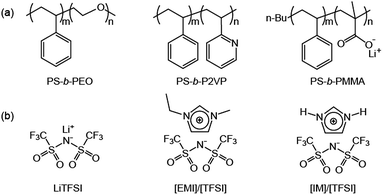
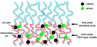
Coil–coil BCPs with linear architecture are the simplest BCP architecture, and thereby they are easily accessible by established polymerization methods. The BCPs consist of two polymeric blocks, which are the ionophilic and ionophobic parts. The ionophilic block selectively accommodates ionic species, and transports ions in microphase-separated nanospaces, while the ionophobic block, with a high glass transition temperature (Tg), imparts mechanical strength.9–11 To date, several coil–coil BCPs have been studied as electrolytes. Among them, a representative example is polystyrene-block-poly(ethylene oxide) (PS-b-PEO) copolymers doped with lithium bis(trifluoromethanesulfone)imide (LiTFSI), which have been intensively studied by the Balsara group (Fig. 2).12–16 Since linear PEO coils are crystalline polymers, rapid ion conduction cannot be expected at RT. Therefore, much research using this BCP was conducted above the PEO melting temperature. The Balsara group's main interest was the ion conduction of the PEO region of polydomain lamellae-forming electrolytes. In recent years, they have systematically studied the effect of the PEO molecular weight, MPEO, on ion conduction. As a consequence, despite the identical lamellar morphology, complex ion conduction was shown to be a function of the MPEO. In the small MPEO limit between 2.7 and 13.7 kg mol−1, the conductivity decreased with increasing MPEO. In contrast, the conductivity in the higher MPEO region increased, and reached the theoretically maximum value at an MPEO of approximately 60 kg mol−1. This non-monotonic dependence of the ion conduction on the MPEO could be explained by two factors: the Tg of the PS block and the width of the conducting PEO layer. The authors suggested that in the small molecular weight limit, the increase in the Tg(PS) changes the dynamics of the PEO coils in the vicinity of the PS/PEO interface. In other words, as the Tg(PS) increases, the PEO chain motion becomes retarded. Once the Tg(PS) levels off with an increasing MPEO, the dominant factor influencing the conductivity is the width of the conducting layer. The central region of the conducting layers becomes more polar as it is further away from the PS/PEO interfacial area, and produces more dissociated ions rather than ion pairs (Fig. 3). Therefore, a larger PEO thickness, associated with a high MPEO, can improve conductivity, because the dependence on the interfacial area becomes insignificant.PS-b-PEO copolymers incorporating ionic liquids (ILs) have been studied.17,18 ILs are unique solvents with some merits such as low vapor pressure, high thermal and electrochemical stability, which are promising for electrolyte applications.19 Recently, Simone and Lodge reported on a series of nanostructured electrolytes consisting of PS-b-PEOs and 1-ethyl-3-methylimidazolium bis(trifluoromethysufonyl)imide, [EMI]/[TFSI] (Fig. 2b).17 Their solution electrolytes displayed Col and Lam nanostructures as a function of the volume fraction of the ionophilic parts, including PEO and [EMI]/[TFSI]. Of the electrolytes, a sample with coexisting lamellar and cylinder (with PS minority) phases exhibited a higher conductivity than the theoretically maximum value expected from the lamellar morphology. This was explained by the coexisting continuous PEO matrix. In addition, as demonstrated by the Balsara group, the conductivity of the lamellar samples was shown to increase with MPEO.12 However, the conductivities of the BCP/IL samples as a function of the ionic concentration behaved differently from that of the BCP/lithium salt samples. In BCP/lithium salt electrolytes, there is an optimum lithium concentration for maximum conductivity, because higher loadings of lithium salts than the optimum decrease the PEO chain mobility due to the strong ion–dipole interaction, resulting in a reduction in conductivity.20 In contrast, the large-sized ILs lead to weaker interaction with PEOs. For this reason, the conductivity was shown to increase continuously with increasing IL concentration.
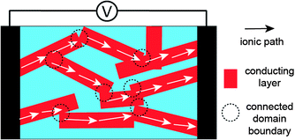
Poly(styrene-block-2-vinylpyridine) (PS-b-P2VP) was also used as an electrolyte BCP mixed with ILs (Fig. 2a).21,22 Hoarfrost et al. investigated the effect of the nanostructure on ionic conductivity for the mixtures of PS-b-P2VP and ILs. The authors used two different ILs, imidazolium TFSI ([IM]/[TFSI]) and [EMI]/[TFSI] (Fig. 2b). They found that the temperature dependence of the conductivity is a function of the amount of IL in the P2VP region. This indicates that the Tg of the P2VP block decreases as the amount of IL increases. In addition, they demonstrated that the concentration dependence of the conductivity is determined by the overall volume fraction of IL. The above argument is valid in cases where the morphology of the electrolyte system does not significantly influence conductivity. This means that the conducting structures (even in the Lam phase) are continuously networked, possibly leading to three-dimensional ionic transport. For this, the authors proposed a percolated IL network for the ionic transport in segregated morphologies (Fig. 4).
Ioannou et al. reported on poly(styrene-block-methacrylic acid) (PS-b-PMAA) electrolytes (Fig. 2a).23 The carboxylate groups of the PMMA block were coordinated with lithium ions, producing single-ion polymer electrolytes. The lithium complexation enhanced the microphase-separation and stiffened the PMMA backbone. In comparison to the acid forms, the lithium-coordinated BCPs showed higher ion conductivities by three orders of magnitude. However, the absolute conductivity values were less than 10−7 S cm−1, and, as such, this BCP system seems to be limited in terms of the battery applications.
3 Dendritic BCP electrolytes
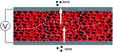
In comparison to linear polymer chains, branched chains with an identical molecular weight exhibit lower Tg values.24 This means that branched polymers are more mobile because of more flexible chain ends, producing extra free volume. In addition, the structural modification into branched chains can reduce the melting points of crystalline polymers. Therefore, the replacement of linear chains with branched ones is advantageous for making better solvent-free electrolyte materials. Indeed, star and hyperbranched PEO electrolytes suppressed PEO crystallization, which increased ionic conductivities at RT.25,26 However, branched ionophilic PEOs cannot support sufficient mechanical strength. Thus, nanostructured BCP assemblies may be an approach to impart mechanical strength to electrolytes containing branched ionophilic groups. Dendritic polymers are a branched building block with regular chain architecture and well-defined molecular weight, and, as such, they are suitable for the systematic study of BCP electrolytes.According to recent reports, Col and Cubmi phases in dendron–coil systems should stabilize over a wide range of block compositions in the phase diagram, and hence, they should be experimentally easy to obtain.28 Furthermore, due to the molecular topology, hydrophilic dendrons should predictably be located in the continuous matrix. Since the morphologies (Cubmi, Col, and Cubbi), except for the Lam phase, consist of continuous ionophilic matrixes, enhanced three-dimensional ionic transportation can be obtained (Fig. 5).
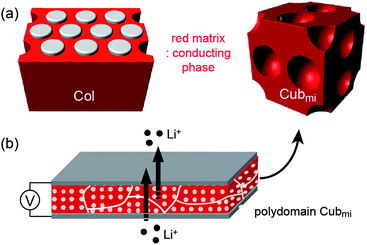 | ||
| Fig. 5 Schematic illustrations of (a) the Col and Cubmi structures with the ionophilic matrixes, and (b) non-tortuous ion conduction in the polydomain Cubmi phase. | ||
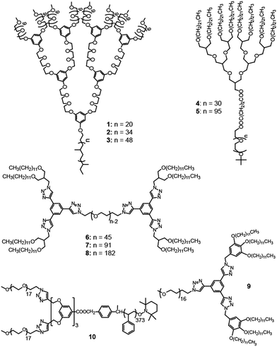
Recently, the Cho group prepared ionophilic polyether dendritic molecules and employed them for BCP electrolytes.29,30 In addition to the ionic transport efficiency, they focused on the mechanical strength, i.e., the elastic modulus (G′). The mechanical strength should be considered as another important parameter to evaluate electrolytes, because more mechanically robust electrolytes suppress critical dendritic growth more efficiently in lithium secondary batteries. The BCPs consisted of PEO-like dendritic and linear poly(ethylene-alt-propylene) (PEP) blocks (Fig. 5a).31 Since the ionophilic PEO blocks were dendritically architectured, no PEO crystalline melting was observed. Ion-doped samples with a lithium concentration per ethylene oxide ([Li+]/[EO]) of 0.02 exhibited various LC morphologies such as Cubmi (1-Li+), Col (2-Li+ and 3-Li+), and Lam (3-Li+) phases as a function of the dendron generation, PEP coil length, and/or temperature.30 The Col and Cubmi LC phases displayed similar ionic conductivities, while lower conductivities were observed in the Lam LC phase. This conductivity behavior indicates that the Col and Cubmi phases are composed of continuous ionophilic matrixes (Fig. 5a). The authors also investigated the grain boundary effect in the Cubmi LC phase. Direct evidence was provided by comparing the conductivities between polydomain and monodomain samples. The conductivities were almost identical. This means that no orientation effort needs to be expended in the Col and Cubmi samples consisting of ionophilic continuous matrixes. In addition to the ionic conductivity, the Cubmi phase showed the highest elastic moduli (G′) of more than ∼106 Pa.
On the other hand, aliphatic polyether dendrons with ionophobic alkyl peripheries were conjugated with ionophilic linear PEO coils in the preparation of BCP electrolytes. Cho and Wiesner reported on an ion-transporting dendron–coil BCP system doped with lithium triflate.32 The ionic sample (4-Li+) from 4 exhibited a Cubmi phase, while the ionic sample (5-Li+) from 5 displayed Col, Lam, and Cubbi phases as a function of temperature. The observed ionic conductivities were strongly dependent upon the dimensionality of the ionophilic domain structures. In particular, the Cubbi phase revealed the highest conductivity, which could be explained by its three-dimensional ion-conducting network structure (Fig. 7). The Cubbi phase is a geometrically versatile nanostructure for ion conduction, and thereby it does not have to be macroscopically aligned.
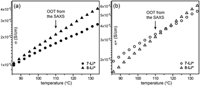
Recently, Choi et al. reported on ABA-type BCPs (6–8) consisting of an ionophilic PEO (B block) coil and two mesogenic dendrons (A block) with four octadecyl peripheries via stepwise click reactions (Fig. 6).33 The electrolyte samples were prepared by doping lithium triflate. As a click reaction was involved in the BCP synthesis, the Y-shaped conjugate triazolyl derivative exists between the ionophilic PEO and ionophobic alkyl peripheries, and acts as a mesogenic group in the melt.34 The authors pointed out that the BCPs shared the characteristics of BCPs and conventional LC assembling systems. Indeed, a typical optical texture of columnar LC phases was observed in the microscopic investigation. From the electrolyte samples (6-Li+–8-Li+), Col, Cubbi and Lam LC phases were revealed depending on the volume fraction (f) of the ionophilic block and/or temperature. Among the electrolytes, 7-Li+ exhibited the Cubbi and Lam LC phases as the temperature increased. The small angle X-ray scattering (SAXS) analysis indicated that the order-to-order transition (OOT) from the Cubbi to Lam phase occurred at 110 °C. However, no considerable change at the OOT could be seen in the original conductivity (σ) curve (Fig. 8a). To characterize the OOT, the authors used a normalized conductivity (σ* = σ/f). By comparing the normalized conductivity curves of 7-Li+ and 8-Li+ showing only a lamellar LC phase, the σ* curves were found to swap over at the OOT temperature (Fig. 8b). This means that the normalized conductivity gives more accurate information in terms of describing the electrolyte's morphological behavior.
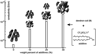
The addition of small additives to BCP electrolytes renders positive effects such as crystallization depression and conductivity enhancement. Choi and Cho investigated the correlation between the ion-conducting and LC properties in a mixture system composed of a dendron–coil (9), a hydrophilic additive, and lithium triflate (Fig. 9).35 The dendron–coil BCP was also prepared using click chemistry, which then contained a disc-type mesogenic aromatic, similar to the above ABA-type BCPs. The used additive is non-volatile and non-crystalline, which could be suitable for electrolyte applications. By adding an additive mixture bearing lithium triflate salt ([Li+]/[EO] = 0.05), a series of electrolytes with the additive weight fractions (fw) of 10%, 20%, and 30% were prepared. In contrast to the undoped dendron–coil (9) showing a Col LC phase, a biphasic LC phenomenon exhibiting Col and Cubbi phases was observed in the electrolytes with fw = 10% and 20%. By increasing fw, the Cubbi LC phase became dominant, and finally only the Cubbi phase remained in the sample with fw = 30%. The ionic conductivity in the biphasic cases reflected the sum of the ion transporting properties of the two LC structures. The ionic conductivity increased by increasing the portion of the Cubbi phase (Fig. 9). The conductivity value increased approximately 2.5 times with each additive addition. The authors explained that the conduction enhancement is attributed to the interplay between the high mobility of the additive and the LC phase change from a one-dimensional to a three-dimensional form of the ion-conducting domain.
Cai et al. reported on a similar dendron–coil BCP (10) and their electrolytes were doped with lithium triflate.36 The BCPs comprise a semirigid dendron with ionophilic PEO peripheries and a linear PS coil. On the basis of the observed Tg of the dendron block upon ion doping, it was shown that the electrolyte system was microphase-separated. Depending on the different degrees of chain branching, a morphological difference was observed. The conductivities from the BCP electrolytes were measured to be less than 10−6 S cm−1 at RT.
In addition to above-described dendron–coil BCP systems, another dendritic LC system is block codendrimers (BCDs), where two physically different dendrons are covalently bound at the center.37–39 In comparison to BCPs, this BCD system has had little investigation. BCDs are a different class of self-assemblers from linear block copolymers and dendron–coil hybrids.
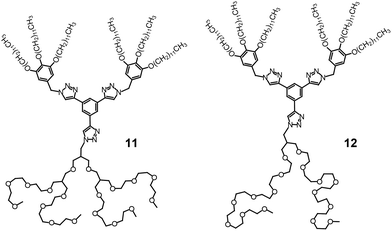
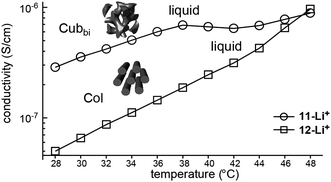
Choi et al. attempted to prepare nanostructured electrolytes using a BCD system.40 The morphology was systematically manipulated by simply varying the degree of chain branching in the hydrophilic dendron structure. The authors presented two BCDs 11 and 12 consisting of a hydrophobic Percec-type dendron and hydrophilic aliphatic polyether dendrons (Fig. 10). The undoped BCDs displayed no LC phase, but upon doping with lithium salt, LC phases were induced in both doped electrolytes. The electrolyte (11-Li+) from 11 showed a Cubbi phase, but the other ionic sample (12-Li+) from 12 formed a Col phase. The authors suggested that the distinct LC properties are associated with the degree of branching in the ionophilic PEO dendron. For the tetrabranched dendron, the higher grafting density of the PEO branches produced greater lateral expansion, which led to the Cubbi structure. Based on the LC morphological analysis, their morphology-dependent ionic conductivities were investigated (Fig. 11). The Cubbi sample displayed approximately 5.4 times higher values than the Col sample. Additionally, upon entering the structureless liquid phases, the conductivities of both ionic samples merged. As remarked on earlier, these results reflect the efficient ion delivery of the Cubbi LC structure consisting of three-dimensional ionic networked channels (Fig. 7).
4 Mini-dendron-based LC electrolytes
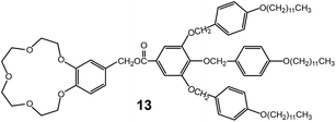
Fan-shaped dendron molecules have shown diverse self-assemblies through variation in dendron generation, focal functionality, and peripheral units.27,41 Mini-dendron assemblers have been employed as nanostructured media for ionic electrolytes. In most cases, the focal units consist of ionophilic moieties, and the peripheral groups are composed of insulating alkyl chains.As a very early work, Percec et al. reported on a mini-dendron system containing a crown ether group at the focal position.42 The mini-dendron (13) doped with sodium triflate was shown to self-assemble into a Col phase (Fig. 12). The slope of the conductivity curve abruptly changed at the phase transitions from crystalline to LC, to the isotropic liquid phase. The conductivity increased steeply in the LC phase. However, the measured conductivity values were less than 10−6 S cm−1 even at high temperatures near 100 °C. Although there are several factors involved in generating the low conductivity values, no macroscopic orientation must be the main one. When utilizing the discrete Col LC phase, the inevitable complex ionic pathway in the polydomain Col delays ion-conduction. Therefore, in order to overcome this intrinsic problem, the one-dimensional ion-conducting columns have to be macroscopically aligned perpendicularly to the two electrodes.
The Kato group prepared many LC ILs based on the fan-shaped mini-dendron system, and then investigated the ionic transportation behavior of one-dimensional Col phases.43–45 They could macroscopically align supramolecular columns using several orientation techniques such as shearing and the surface modification of substrates. Percec-type IL mini-dendrons (14 and 15) containing imidazolium salt formed Col LC phases at RT (Fig. 13a). The Kato group could obtain two different macroscopic orientations of the columns in the Col phase by shearing perpendicular and parallel to the gold electrodes, and they examined the influence of the orientation on the ionic conductivity (Fig. 13b). According to the experimental data, the ionic conductivities parallel to the columnar axis (σpar) were more than 10 times as high as the ionic conductivities perpendicular to the columnar axis (σper). The IL dendrons could dissolve lithium salts and the enhancement of the ionic conductivity was observed. This suggests that the IL dendrons can be used as a platform material for lithium-battery applications.
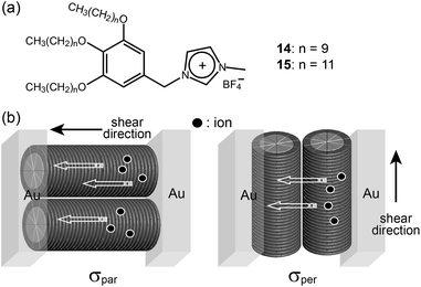 | ||
| Fig. 13 Molecular structures of (a) mini-dendrons containing imidazolium salt, and (b) ion conduction parallel (left) and perpendicular (right) to the columnar axis. | ||
Based on the above knowledge, the Kato group prepared two types of ion-conducting polymer films through the photo-polymerization of a dendritic IL showing a Col LC phase.46 The monomeric IL (16) contained two acrylate groups at the periphery (Fig. 14a). Two orientation techniques were applied to align the columns differently. In addition to the shear method for the alignment parallel to a glass surface, a surface modification of glass and indium tin oxide (ITO) with 3-(aminopropyl)triethoxysilane (APS) yielded a columnar orientation perpendicular to the substrate surface (Fig. 14b). The film prepared by the surface-modification technique exhibited greater conduction anisotropy (σpar/σper) than that of the film prepared by the shear-orientation technique.
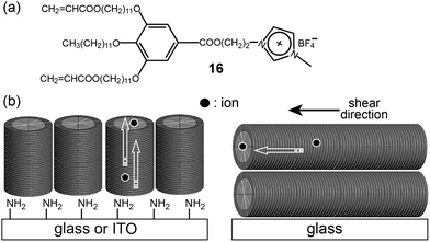 | ||
| Fig. 14 Molecular structure of (a) the monomeric minidendron (16), and (b) the columnar orientations by the surface APS groups (left) and shear stress (right). | ||
Ion-conducting Col assemblies were also accomplished in a supramolecular dendritic IL system. A 1![[thin space (1/6-em)]](https://www.rsc.org/images/entities/char_2009.gif) :
:![[thin space (1/6-em)]](https://www.rsc.org/images/entities/char_2009.gif) 1 mixture of an IL (1-butyl-3-methylimidazolium bromide) and a dendron (17) with a diol group at the focal point displayed a Col LC phase (Fig. 15).47 The notable feature of the supramolecular ionic conductor was that it exhibited conductivity that was more than 700 times higher than that of the corresponding covalent-type columnar IL (18) (Fig. 15). The authors suggested that the ionic enhancement of the supramolecular system was due to the better mobility of the ionic part.
1 mixture of an IL (1-butyl-3-methylimidazolium bromide) and a dendron (17) with a diol group at the focal point displayed a Col LC phase (Fig. 15).47 The notable feature of the supramolecular ionic conductor was that it exhibited conductivity that was more than 700 times higher than that of the corresponding covalent-type columnar IL (18) (Fig. 15). The authors suggested that the ionic enhancement of the supramolecular system was due to the better mobility of the ionic part.
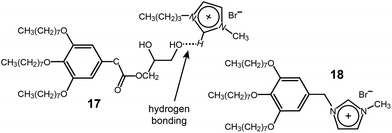 | ||
| Fig. 15 (a) Supramolecular complex of the dendritic diol (17) and 1-butyl-3-methylimidazolium bromide, and (b) the corresponding covalent-type IL (18). | ||
When considering the morphological merit concerning efficient ion conduction, the Cubbi phase is more ideal than the low-dimensional Col phase (Fig. 7). Recently, several ionic mini-dendrons were reported to self-assemble into Cubbi LC phases, which were employed as electrolyte materials (Fig. 16).48,49 The molecules (19–21) contained ammonium or phosphonium salts at the focal point. The formation of the Cubbi LC phase was found to be dependent upon the cationic moiety, alkyl chain length, and anion. The phosphonium-based Cubbi electrolyte (21) showed conductivities in the order of 10−4 S cm−1 at RT, which were much higher than those of the ammonium-based Cubbi electrolyte (19). These excellent ion-conduction values persisted in the mixture of electrolytes containing lithium tetrafluoroborate.
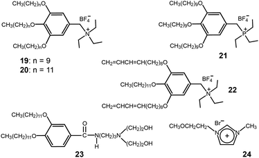 | ||
| Fig. 16 Molecular structures of the ionic and amphiphilic dendrons (19–23) and an imidazolium IL (24). | ||
Similarly to the ion-conducting polymerized Col films, the Kato group made Cubbi polymer films by employing the same photo-polymerization as was used in the Col films.50 The peripheral units of the wedge-shaped ionic salt (22) were functionalized with two polymerizable 1,3-diene groups (Fig. 16). Due to the three-dimensional interconnected ionic paths, the Cubbi polymer film showed higher conductivities than the films obtained from the Col and isotropic liquid phases.
Binary mixtures of amphiphilic dendrons (23) based on a diethanolamine group and an imidazolium IL (24) were shown to co-organize into a Cubbi LC phase (Fig. 16).51 The induction of the Cubbi LC phase was strongly associated with the hydrogen bonding between the ILs and amphiphiles. As the mole fraction of the IL (24) increased, the ionic conductivity in the Cubbi LC phase increased.
A more practical Cubbi LC example applicable to battery electrolytes was reported on by the Gin group.52 They prepared cross-linked polymeric materials by mixing a monomeric dendritic salt (25) with a 0.245 M LiClO4–PC solution (Fig. 17). The monomeric dendron contains lithium 2-aminoethanesulfonate at the focal site, which was compatible with the electrolyte solution. The electrolyte composite contained 15 wt% 0.245 M LiClO4–PC solution. It formed a lyotropic Cubbi LC phase, and, subsequently, was photo-polymerized by UV radiation. Even after a photo cross-linking, the Cubbi phase was intact, as confirmed by optical polarized microscopy (OPM) and X-ray diffraction. The polymerized films were flexible and free-standing. The RT conductivity was 9 × 10⁻⁴ S cm−1, which is comparable to that of gelled PEO systems.53 The conductivity result indicates a liquid-like mobility in the ionic channels.
5 Rod-type LC electrolytes
Rod-like LC materials self-organize into Lam LC phases. The introduction of ionophilic OEO or PEO coils in the rod-type LC system produces Lam LC electrolytes that function via two-dimensional ion conduction.The Wright group reported on the ion conduction of PEO-based LC polymers bearing alkyl side chains (Fig. 18a).54–56 The alkyl chains showed linear conformations like rod mesogens, while the PEO coils adopted extended helical structures due to complexation with lithium salts (Fig. 18b). These chain organizations resulted in Lam LC structures. In the LC phase, lithium cations resided in the PEO helical channels, which could reduce ionic aggregates. In most cases, the conductivities measured at RT were in the order of 10−7 S cm−1. The addition of amphiphilic block copolymers increased conductivity up to the order of 10−4 S cm−1 at RT.57
 | ||
| Fig. 18 (a) Molecular structure of a PEO-based LC polymer (26), and (b) the organization of ions in the Lam LC phase. | ||
Layered poly(para-phenylene)s (27) with lateral PEO chains were studied by Wegner and coworkers (Fig. 19a).58,59 The main-chain polymers were complexed with lithium salts, resulting in Lam electrolytes (Fig. 19b). The conductivities of the electrolytes were found to be ∼10−6 S cm−1. To increase the ionic conductivity, small OEG additives were inserted in the PEO region. Consequently, the conductivity increased 10 times due to the plasticization effect of the additive.
 | ||
| Fig. 19 (a) Molecular structures of poly(para-phenylene)s with lateral PEO chains (27), and (b) the schematic of the Lam LC phase. | ||
Rod–coil–rod LC molecules (28 and 29) with an ionophilic OEG functioned as a two-dimensional ion conductor (Fig. 20a).60–62 The electrolytes with lithium triflate exhibited smectic LC phases. Since the Lam morphology consists of two-dimensional layers, the layers should be macroscopically aligned perpendicular to two electrodes in order to improve ion conduction. Ohtake et al. homeotropically aligned the layers of the Lam phase on the glass substrate (Fig. 20b). They compared the conductivities of the aligned monodomain and non-aligned polydomain samples. The conductivity from the oriented Lam LC phase was greater than that from the polydomain Lam phase by about two orders of magnitude.
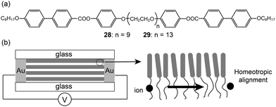 | ||
| Fig. 20 (a) Molecular structures of the rod–coil–rod LC molecules (28 and 29), and (b) the ion-conduction of the homeotropically aligned sample. | ||
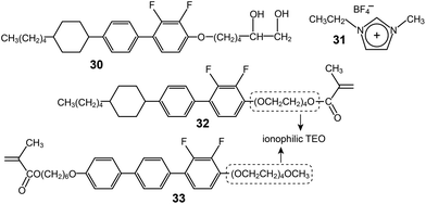
Furthermore, an identical homeotropic alignment was applied to a mixture of an AB-type diol-based rod mesogen (30) and a conventional IL (31) (Fig. 21).63 Depending on the position of the electrodes, two conductivities parallel and perpendicular to the layer, σpar and σper, could be measured. A remarkable conductivity anisotropy (σpar/σper) of 3.1 × 10³ was observed at 73 °C. The maximum σpar was measured as 4.1 × 10⁻³ S cm−1 in the Lam phase at 192 °C.
A rod–coil LC molecule (32) with a polymerizable methacrylate group were studied by Kishimoto and coworkers.64 A tetra(ethylene oxide) (TEO) group was placed between the rod and methacrylate groups (Fig. 21), and complexed with lithium triflate. The LC complexes formed smectic (Lam) phases, which were properly homeotropically aligned both on glass and ITO substrates. An in situ photo-polymerization in the homeotropic Lam structures produced free-standing films. The magnitude of the conductivity anisotropy was in the order of 103. However, the highest conductivity values were, at most, 10−6 S cm−1. This is because both the ends of the TEO coil are bound to the less flexible groups, and thereby segmental motions of the TEO must be restricted. In order to enhance ion-conduction, the authors modified the position of the ionophilic TEO coil.65 They placed the TEO at the terminal, through which a TEO end remained flexible after the polymerization (Fig. 21). Indeed, the Tg of 33 was −45 °C, which was much lower than that of 32. Through this molecular reforming, the conductivity (σpar) of the Lam LC electrolyte considerably increased up to 10−3 S cm−1 at RT.
The anisotropic conductivity parallel to the layer, σpar, could be achieved from sandwiched ITO cells coated with a rubbed polyimide (35).66 The lithium triflate complexes of 34 formed a smectic A phase. They were injected into bare and polyimide-coated ITO cells, respectively. In the uncoated ITO cell, the homeotropic arrangement of the LC molecules occurred, through which the σper could be obtained. In contrast, in the coated ITO cell, layers were aligned vertically to the ITO electrode, and thus the σpar could be obtained (Fig. 22b). The σpar was higher than the σper by more than three orders of magnitude.
 | ||
| Fig. 22 (a) Molecular structures of the rod–coil molecule (34) and polyimide (35), and (b) the molecular organization in the polyimide-coated ITO cell. | ||
Anisotropic one-dimensional ion conductions were observed in rod-like mesogen-based polymer membranes. Iyoda and coworkers prepared a BCP (36) with azo-benzene rod mesogens and a PEO coil, and made ionic complexes with lithium triflate (Fig. 23).67 The ionic BCP spontaneously formed perpendicularly oriented PEO cylindrical domains (Fig. 23b). Using the LC membrane structure, the authors measured anisotropic conductivities by varying the electrode positions. Although the conductivities were detected to be at best in the order of 10−9 S cm−1 at RT, the conductivity anisotropy reached more than 40. Majewski et al. reported on similar BCP electrolyte membranes showing a Col phase.68 They prepared BCPs (37) containing an ionophilic PEO coil and cyanobiphenyl mesogens, and made electrolyte samples by doping with lithium perchlorate. The BCP electrolytes formed Col structures consisting of one-dimensional PEO domains (Fig. 23b). In particular, the PEO column could be macroscopically aligned through exposure to a magnetic field. With an increasing magnetic field strength of up to 6 T, the columns were well aligned, perpendicular to the substrate. The authors examined orientation-dependent ionic conductivities. Similarly to Iyoda's examples, the σpar at RT showed a maximum value in the order of 10−7 S cm−1, which was higher than the σper and the conductivity (σran) of the polydomain sample.
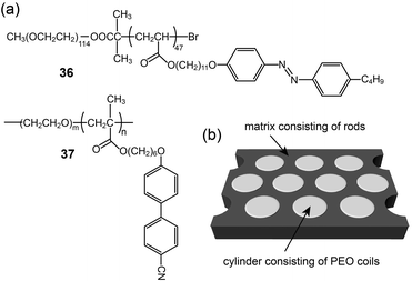 | ||
| Fig. 23 (a) Molecular structures of BCPs (36 and 37), and (b) the self-assembled membrane structure. | ||
LC elastomeric electrolytes exhibited anisotropic ion conduction.69 The monomer (38) consisted of a cinnamic group-based aromatic rod, an ionophilic tri(ethylene oxide), and a terminal vinyl unit (Fig. 24). The mixture of the monomer, the cross-linker (39), the polyhydromethylsiloxane (PHMS) backbone, and lithium triflate exhibited a Lam LC phase. The vinyl units of 38 and 39 could be combined with PHMS in the presence of a catalyst, resulting in elastomeric electrolytes. The macroscopic orientation was performed by applying a uniaxial stress to the slightly cross-linked elastomer gel, and then the anisotropic ion mobilities were investigated by 7Li and 19F nuclear magnetic resonance (NMR) spectroscopies. According to the NMR analyses, the mobility anisotropy of the lithium cation of the elastomer was found to be 6, which was much smaller than that (∼100) of the lithium cation of the monomeric sample.
6 Conclusions and outlook
LC materials have unique dynamic and mechanical properties such as free segmental motions at the molecular level and non-fluidic order in the supramolecular level. These physical features are promising for electrolyte materials. In this review article, we summarized nanostructured electrolytes from diverse molecular systems such as coil–coil BCPs, dendritic BCPs, mini-dendron LCs, and aromatic rod-based LCs. The molecular systems consisted of ionophilic and ionophobic blocks, and by complexation with lithium salt and/or ILs, ion-conducting electrolytes could be prepared. The LC electrolyte systems enable the decoupling of ion-conduction and mechanical properties, which can be individually engineered. As already described in the main text, ion-conduction is influenced by both the morphology and chain mobility of ionophilic block. Therefore, when devising an electrolyte material, more attention has to be paid to the structural design of LC electrolytes, which influence the ionic movement on both the supramolecular and molecular levels.To improve ionic movement in the molecular level, ionophilic blocks had better have high dielectric constant and low Tg. First, increasing the dielectric constant assists ion dissociation. Second, lowering the Tg improves chain mobility. In particular, in terms of chain mobility, branched or graft chains with multiple chain ends are advantageous in the LC design, because they have lower Tgs than their linear counterparts, and furthermore, they are hard to crystallize, which is useful for RT-operated device applications. In addition to such a molecular design approach, an appropriate additive can be used to enhance ionic movement. Among ionophilic additives, ILs are promising due to their non-volatility, high dielectric constant and electrochemical stability. We feel that ILs will be used as a main element when preparing new LC electrolytes, although they have been studies limitedly to date.
The morphology selection is another independent factor to affect conducting performance. Well-known LC structures such as Lam, Col, Cubbi, and Cubmi phases have been employed. Through rational molecular design, the architecture of the conducting domains could be tailored, to produce one-, two-, and three-dimensional ionic conduction. In the polydomain samples, the Cubbi phase is the ideal morphology because it can offer ionic pathways for three-dimensional conduction. In contrast, polydomain Col and Lam phases are inferior to the Cubbi due to their intrinsic complicated conducting pathways. To improve ion conduction, macroscopic orientation of the Col and Lam structures is required. Several alignment techniques, such as the modification of the surface group of substrates, shearing, and magnetic field forces were employed, so as to enable the measurement of the anisotropic conductivities, σpar and σper, with respect to the electrode positions. Three-dimensional ion conduction could be achieved using the matrixes of the Cubmi and Col LC phases formed by BCPs containing ionophilic dendritic blocks.
The mechanical strength of electrolyte materials is another important requirement. To increase secondary battery capacity, Li metal has to be employed as the negative electrode. To use Li metal safely, however, electrolyte materials should be mechanically robust: otherwise, critical dendrite growth occurs more effectively at Li metal/electrolyte interface.70 Therefore, the development of mechanically strong electrolytes is as important as the development of highly conductive electrolytes. Among the LC morphologies, the cubic structures such as Cubmi and Cubbi are advantageous due to their highly elastic moduli coming from their cubic symmetry. When using Col and Lam phases, post-polymerizations in the LC phases increase the mechanical strength. Several examples described in this article could be obtained as free-standing films. Additionally, a polymeric group with high Tg can be used as the insulating block (e.g., PS block in PS-b-PEO electrolytes), because they are mechanically robust below Tg.
Ion-conducting materials using the LC-assembly concept could be one of the next-generation of electrolytes, because they may overcome the demerits such as critical dendrite growth and solvent evaporation that are present in conventional solvent-based electrolytes. Nevertheless, the unsolved challenge for LC electrolytes is to increase the conductivity up to the level (10−3 S cm−1 at RT) of solvent electrolytes. More diverse methods, e.g., the design of new electrolyte molecules, and the blending of diverse additives, etc., should be attempted to optimize the electrolyte performance in terms of both ion conduction and mechanical strength. By furthering this research avenue, high-performance LC electrolytes are expected to be obtained sooner or later. Considering only the current electronic device market, the LC electrolyte approaches may not overcome the economical efficiency of the existing solvent-based electrolytes. However, the solvent-based electrolytes are intrinsically inappropriate for the next-generation electronic markets such as flexible and ultra-thin devices. Therefore, to keep pace with upcoming industries, the solvent-free LC electrolyte approach could be employed to develop new flexible and ultra-thin batteries.
Notes and references
- P. G. Bruce, B. Scrosati and J.-M. Tarascon, Angew. Chem., Int. Ed., 2008, 47, 2930 CrossRef CAS PubMed.
- M. Ishikawa, M. Morita, M. Asao and Y. Matsuda, J. Electrochem. Soc., 1994, 141, 1105 CrossRef CAS PubMed.
- D. E. Fenton, J. M. Parker and P. V. Wright, Polymer, 1973, 14, 589 CrossRef CAS.
- V. Chandrasekhar, Adv. Polym. Sci., 1998, 135, 139 CrossRef CAS PubMed.
- R. Mezzenga, P. Schurtenberger, A. Burbidge and M. Michel, Nat. Mater., 2005, 4, 729 CrossRef CAS PubMed.
- C. A. Tyler and D. C. Morse, Macromolecules, 2003, 36, 3764 CrossRef CAS.
- T. Kato, N. Mizoshita and K. Kishimoto, Angew. Chem., Int. Ed., 2006, 45, 38 CrossRef CAS PubMed.
- M. Funahashi, H. Shimura, M. Yoshio and T. Kato, Struct. Bonding, 2008, 128, 151 CrossRef CAS.
- D. T. Hallinan and N. P. Balsara, Annu. Rev. Mater. Res., 2013, 43, 503 CrossRef CAS.
- M. J. Park, I. Choi, J. Hong and O. Kim, J. Appl. Polym. Sci., 2013, 129, 2363 CrossRef CAS.
- P. P. Soo, B. Huang, Y.-I. Jang, Y.-M. Chiang, D. R. Sadoway and A. M. Mayes, J. Electrochem. Soc., 1999, 146, 32 CrossRef CAS PubMed.
- M. Singh, O. Odusanya, G. M. Wilmes, H. B. Eitouni, E. D. Gomez, A. J. Patel, V. L. Chen, M. J. Park, P. Fragouli, H. Iatrou, N. Hadjichristidis, D. Cookson and N. P. Balsara, Macromolecules, 2007, 40, 4578 CrossRef CAS.
- A. Panday, S. Mullin, E. D. Gomez, N. Wanakule, V. L. Chen, A. Hexemer, J. Pople and N. P. Balsara, Macromolecules, 2009, 42, 4632 CrossRef CAS.
- N. S. Wanakule, A. Panday, S. A. Mullin, E. Gann, A. Hexemer and N. P. Balsara, Macromolecules, 2009, 42, 5642 CrossRef CAS.
- S. A. Mullin, G. M. Stone, A. Panday and N. P. Balsara, J. Electrochem. Soc., 2011, 158, A619 CrossRef CAS PubMed.
- R. Yuan, A. A. Teran, I. Gurevitch, S. A. Mullin, N. S. Wanakule and N. P. Balsara, Macromolecules, 2013, 46, 914 CrossRef CAS.
- P. M. Simone and T. P. Lodge, ACS Appl. Mater. Interfaces, 2009, 1, 2812 CAS.
- I. Y. Choi, H. M. Ahn and M. J. Park, Macromolecules, 2011, 44, 7327 CrossRef CAS.
- H. Ohno, Electrochemical Aspects of Ionic Liquids, John Wiley & Sons, Hoboken, NJ, 2011 Search PubMed.
- W. H. Meyer and W. H. Meyer, Adv. Mater., 1998, 10, 439 CrossRef CAS.
- M. L. Hoarfrost and R. A. Segalman, Macromolecules, 2011, 44, 5281 CrossRef CAS.
- M. L. Hoarfrost and R. A. Segalman, ACS Macro Lett., 2012, 1, 937 CrossRef CAS.
- E. F. Ioannou, G. Mountrichas, S. Pispas, E. I. Kamitsos and G. Floudas, Macromolecules, 2008, 41, 6183 CrossRef CAS.
- J. Song and B.-K. Cho, Bull. Korean Chem. Soc., 2008, 29, 1167 CrossRef CAS.
- M. K. Stowe, P. Liu and G. L. Baker, Chem. Mater., 2005, 17, 6555 CrossRef CAS.
- C. J. Hawker, F. Chu, P. J. Pomery and D. J. T. Hill, Macromolecules, 1996, 29, 3831 CrossRef CAS.
- B. Rosen, C. J. Wilson, D. A. Wilson, M. Peterca, M. R. Imam and V. Percec, Chem. Rev., 2009, 109, 6275 CrossRef CAS PubMed.
- G. M. Grason, B. A. DiDonna and R. D. Kamien, Phys. Rev. Lett., 2003, 91, 58304 CrossRef.
- H.-Y. Kim, J. Song, S.-H. Kim, E. Lee, J.-K. Lee, W.-C. Zin and B.-K. Cho, Chem.–Eur. J., 2009, 15, 8683 CrossRef CAS PubMed.
- J. Song and B.-K. Cho, Chem. Commun., 2012, 48, 6821 RSC.
- J. Song and B.-K. Cho, Soft Matter, 2012, 8, 3419 RSC.
- B.-K. Cho, A. Jain, S. M. Gruner and U. Wiesner, Science, 2004, 305, 1598 CrossRef CAS PubMed.
- S. Choi and B.-K. Cho, Soft Matter, 2013, 9, 4241 RSC.
- M.-H. Ryu, J.-W. Choi, H.-J. Kim, N. Park and B.-K. Cho, Angew. Chem., Int. Ed., 2011, 50, 5737 CrossRef CAS PubMed.
- J.-W. Choi and B.-K. Cho, J. Polym. Sci., Part A: Polym. Chem., 2011, 49, 2468 CrossRef CAS.
- H. Cai, G. Jiang, Z. Shen and X. Fan, Macromolecules, 2012, 45, 6176 CrossRef CAS.
- V. Percec, M. R. Imam, T. K. Bear, V. S. K. Balagurusamy, M. Peterca and P. A. Heiney, Angew. Chem., Int. Ed., 2005, 44, 4739 CrossRef CAS PubMed.
- M. Yang, W. Wang, F. Yuan, X. Zhang, J. Li, F. Liang, B. Minch and G. Wegner, J. Am. Chem. Soc., 2005, 127, 15107 CrossRef CAS PubMed.
- J.-W. Choi, M.-H. Ryu, E. Lee and B.-K. Cho, Chem.–Eur. J., 2010, 16, 9006 CrossRef CAS PubMed.
- J.-W. Choi and B.-K. Cho, Soft Matter, 2011, 7, 4045 RSC.
- B.-K. Cho, Polym. J., 2012, 44, 475 CrossRef CAS.
- V. Percec, G. Johansson, J. Heck, G. Ungar and S. V. Batty, J. Chem. Soc., Perkin Trans. 1, 1993, 1411 RSC.
- M. Yoshio, T. Mukai, H. Ohno and T. Kato, J. Am. Chem. Soc., 2004, 126, 994 CrossRef CAS PubMed.
- M. Yoshio, T. Ichikawa, H. Shimura, T. Kagata, A. Hamasaki, T. Mukai, H. Ohno and T. Kato, Bull. Chem. Soc. Jpn., 2007, 80, 1836 CrossRef CAS.
- S. Yazaki, Y. Kamikawa, M. Yoshio, A. Hamasaki, T. Mukai, H. Ohno and T. Kato, Chem. Lett., 2008, 538 CrossRef CAS.
- M. Yoshio, T. Kagata, K. Hoshino, T. Mukai, H. Ohno and T. Kato, J. Am. Chem. Soc., 2006, 128, 5570 CrossRef CAS PubMed.
- H. Shimura, M. Yoshio, K. Hoshino, T. Mukai, H. Ohno and T. Kato, J. Am. Chem. Soc., 2008, 130, 1759 CrossRef CAS PubMed.
- T. Ichikawa, M. Yoshio, A. Hamasaki, T. Mukai, H. Ohno and T. Kato, J. Am. Chem. Soc., 2007, 129, 10662 CrossRef CAS PubMed.
- T. Ichikawa, M. Yoshio, A. Hamasaki, S. Taguchi, F. Liu, X. Zeng, G. Ungar, H. Ohno and T. Kato, J. Am. Chem. Soc., 2012, 134, 2634 CrossRef CAS PubMed.
- T. Ichikawa, M. Yoshio, A. Hamasaki, J. Kagimoto, H. Ohno and T. Kato, J. Am. Chem. Soc., 2011, 133, 2163 CrossRef CAS PubMed.
- T. Ichikawa, M. Yoshio, S. Taguchi, J. Kagimoto, H. Ohno and T. Kato, Chem. Sci., 2012, 3, 2001 RSC.
- R. L. Kerr, S. A. Miller, R. K. Shoemaker, B. J. Elliott and D. L. Gin, J. Am. Chem. Soc., 2009, 131, 15972 CrossRef CAS PubMed.
- J. Y. Song, Y. Y. Wang and C. C. Wan, J. Power Sources, 1999, 77, 183 CrossRef CAS.
- F. B. Dias, J. P. Voss, S. V. Batty, P. V. Wright and G. Ungar, Macromol. Rapid Commun., 1994, 15, 961 CrossRef CAS.
- P. V. Wright, Y. Zheng, D. Bhatt, T. Richardson and G. Ungar, Polym. Int., 1998, 47, 34 CrossRef CAS.
- Y. Zheng, F. Chia, G. Ungar and P. V. Wright, Chem. Commun., 2000, 1459 RSC.
- J. Liu, Y. Zheng, Y.-P. Liao, X. Zeng, G. Ungar and P. V. Wright, Faraday Discuss., 2005, 128, 363 RSC.
- U. Lauter, W. H. Meyer and G. Wegner, Macromolecules, 1997, 30, 2092 CrossRef CAS.
- U. Lauter, W. H. Meyer, V. Enkelmann and G. Wegner, Macromol. Chem. Phys., 1998, 199, 2129 CrossRef CAS.
- T. Ohtake, K. Ito, N. Nishina, H. Kihara, H. Ohno and T. Kato, Polym. J., 1999, 31, 1155 CrossRef CAS.
- T. Ohtake, Y. Takamitsu, K. Ito-Akita, K. i Kanie, M. Yoshizawa, T. Mukai, H. Ohno and T. Kato, Macromolecules, 2000, 33, 8109 CrossRef CAS.
- T. Ohtake, M. Ogasawara, K. Ito-Akita, N. Nishina, S. Ujiie, H. Ohno and T. Kato, Chem. Mater., 2000, 12, 782 CrossRef CAS.
- M. Yoshio, T. Mukai, K. Kanie, M. Yoshizawa, H. Ohno and T. Kato, Adv. Mater., 2002, 14, 351 CrossRef.
- K. Kishimoto, M. Yoshio, T. Mukai, M. Yoshizawa, H. Ohno and T. Kato, J. Am. Chem. Soc., 2003, 125, 3196 CrossRef CAS PubMed.
- K. Kishimoto, T. Suzawa, T. Yokota, T. Mukai, H. Ohno and T. Kato, J. Am. Chem. Soc., 2005, 127, 15618 CrossRef CAS PubMed.
- Y. Iinuma, K. Kishimoto, Y. Segara, M. Yoshio, T. Mukai, I. Kobayashi, H. Ohno and T. Kato, Macromolecules, 2007, 40, 4874 CrossRef CAS.
- J. Li, K. Kamata, M. Komura, T. Yamada, H. Yoshida and T. Iyoda, Macromolecules, 2007, 40, 8125 CrossRef CAS.
- P. W. Majewski, M. Gopinadhan, W.-S. Jang, J. L. Lutkenhaus and C. O. Osuji, J. Am. Chem. Soc., 2010, 132, 17516 CrossRef CAS PubMed.
- L. Ramón-Gimenez, R. Storz, J. Haberl, H. Finkelmann and A. Hoffmann, Macromol. Rapid Commun., 2012, 33, 386 CrossRef PubMed.
- T. Tatsuma, M. Taguchi and N. Oyama, Electrochim. Acta, 2001, 46, 1201 CrossRef CAS.
| This journal is © The Royal Society of Chemistry 2014 |


