Influence of different methylene units on the performance of rhodanine organic dyes for dye-sensitized solar cells

Jianghua Zhaoa, Xichuan Yang*a, Ming Chenga, Weihan Wanga and Licheng Sun*ab
aState Key Laboratory of Fine Chemicals, DUT–KTH Joint Education and Research Centre on Molecular Devices, Dalian University of Technology(DUT), 2 Linggong Rd, 116024 Dalian, China. E-mail: yangxc@dlut.edu.cn; Fax: +86 411 84986250; Tel: +86 411 84986247
bKTH Royal Institute of Technology, School of Chemical Science and Engineering, Department of Chemistry, Teknikringen 30, 10044 Stockholm, Sweden. E-mail: lichengs@kth.se; Fax: +46 8 791 2333; Tel: +46 8 790 8127

Received 11th September 2013 , Accepted 4th November 2013

First published on 5th November 2013


Abstract

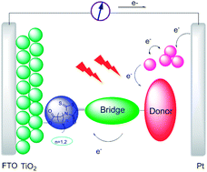
In D–π–A structured organic dyes, rhodanine acetic acid and its derivates have served as electron acceptors successfully. In this work, two single rhodanine organic dyes with different methylene units have been synthesized and applied in dye-sensitized solar cells (DSSCs). The photophysical, electrochemical and photovoltaic properties have been studied systematically. The results show that dye with double methylene units produces a higher photon-to-electron conversion efficiency (η) of 4.5% than that of a single methylene unit dye with a η of 4.1%. Also, it is interesting to notice that the lengthened distance between electron acceptor and TiO2 surface does not decrease the short-circuit current density (Jsc) and IPCE response for both structured dyes. On the contrary, rhodanine dye bearing double methylene units exhibits a better Jsc and IPCE response than the single methylene unit. The explanation for this trend is probably due to the fact that increased methylene units could suppress regeneration between the injected electron and the oxidized dye effectively.


Introduction

Dye-sensitized solar cells (DSSCs) have attracted significant attention as a new generation photovoltaic (PV) device since Grätzel and O'Regan reported them in 1991.1 As the key component in this device, the study of photosensitizers has never been suspended. Metal complexes and metal-free organic dyes represent different developmental directions as photosensitizers. Compared to metal complexes, metal-free organic dyes exhibit many virtues, such as low cost, being environmental friendly, an adjustable structure, and a competitive efficiency. For metal-free organic dyes, the donor–π-conjugated bridge–acceptor (D–π–A) structure is the main molecular configuration. In recent years, a considerable amount of work has been directed towards the electron donor part and the π-conjugation bridge. For example, triphenylamide,2–4 phenothiazine,5 coumarin,6–8 and indoline9–11 have been successfully used as electron donors; thiophene and its derivatives12,13 generally serve as a π-conjugated bridge. Meanwhile, the electron acceptor also plays a major role in the photophysical, electrochemical and photovoltaic properties of DSSCs.

Cyanoacrylic acid and rhodanine are classical electron acceptors in D–π–A structured organic dyes.14–16 Compared to cyanoacrylic acid, rhodanine exhibits a stronger electron withdrawing ability with a widened spectra response, which is beneficial for the improvement of the photocurrent. To obtain a higher photon-to-electron conversion efficiency, most works have focused on lengthening the rhodanine unit to broaden the absorption region of dyes.17,18 For example, Horiuchi and co-workers have designed a series of organic dyes with double or triple rhodanine acetic acid units and obtained the highest η of 8.0% until now.16 However, for a single rhodanine acetic acid unit, the electron acceptor and carboxyl group are separated by a methylene unit. It is interesting to lengthen the number of methylene units between them to tune the distance between the single rhodanine unit and the TiO2 surface, and investigate the influence on the photovoltaic performance of DSSCs. As we know, there are few reports on this kind of molecular design strategy.

In this work, two rhodanine acetic acid dyes with different methylene units have been designed and applied in DSSCs. As displayed in Fig. 1, substituted triphenylamide served as an electron donor; two 3-hexylthiophene units were adopted as a π-conjugation bridge, which can effectively suppress electron recombination on the TiO2–dye–electrolyte interface resulting in a higher open-circuit photovoltage. A single rhodanine unit with one or two methylene units was used as electron acceptor. The photophysical and electrochemical properties and photovoltaic performance of the rhodanine acetic acid dyes were also investigated systematically.


image file: c3ra45034a-f1.tif
Fig. 1 Structures of dye JH501 and dye JH502.

Results and discussion

Photophysical and electrochemical properties

The UV-visible absorption spectra of JH501 and JH502 in CH2Cl2 solution and on TiO2 film are displayed in Fig. 2, and the corresponding photophysical data are listed in Table 1. It can be found that there are two main absorption bands for both dyes. In the higher energy region, an absorption band around 350 nm can be observed for both dyes, which is attributed to the π → π* transition. In the distant region, both JH501 and JH502 exhibit a maximal absorption band at 534 nm and 505 nm, respectively, corresponding to the S0 → S1 transition. The excited state energy calculations also provide evidence for this transition (see ESI). Obviously, a hypochromatic shift can be found for both dyes on the TiO2 surface in comparison with those in solution, which is probably due to the electron-withdrawing inductive effect of the carboxyl group on the rhodanine unit decreasing for the lengthened methylene chain. As present in Fig. 2(b), when JH501 and JH502 were anchored on the TiO2 film, a hypochromatic shift of 31 and 7 nm can be observed for dye JH501 and dye JH502, respectively, indicating that both dyes aggregate on the TiO2 surface in the form of H-type aggregation.19 Furthermore, the maximal absorption peaks for both dyes on the TiO2 surface locate close to each other in comparison with those in solution. This phenomenon implies that the carboxyl group does not play a role in the electron acceptor but is an anchoring group to a great extent, which shows little effect on the spectral response when adsorbed on TiO2 film.
image file: c3ra45034a-f2.tif
Fig. 2 Absorption spectra of JH501 and JH502 in CH2Cl2 solution (a) and on TiO2 film (b).

The electrochemical properties of JH501 and JH502 on TiO2 film have been studied by cyclic voltammetry, and the corresponding data are collected in Table 1. The results indicate that the highest occupied molecular orbital (HOMO) levels of both dyes are more positive than the redox potential of the I/I3 shuttle (0.4 V vs. NHE),20 indicating that the oxidized dye can get regenerated effectively. Furthermore, the lowest unoccupied molecular orbital (LUMO) levels of both dyes are more negative than the conductive band edge (Ecb) of TiO2 (−0.5 V vs. NHE),21 which ensures electron injection. It can also be noted that the number of methylene units has more of an effect on the LUMO levels than that of the HOMO levels for both rhodanine organic dyes. The exited state energy calculations are displayed in the ESI.

The ground state structures of JH501 and JH502 were further optimized by density functional theory (DFT) calculations at the CAMB3LYP/6–31G (d) level. The results are displayed in Table 2. According to the optimized structure, it can be noted that the HOMO levels of JH dyes are distributed along the π system covering the electron donor and partial spacer. The LUMO levels of all dyes are concentrated on the rhodanine unit and partial spacer. The methylene unit for both structured dyes does not get an electron distribution.

Table 1 Absorption and electrochemical data of JH501 and JH502
Dye λmaxa (nm) ε at λmax (M−1 cm−1) λmaxb on TiO2 (nm) E0–0c (V) EHOMOd (V) (vs. NHE) ELUMO (V) (vs. NHE)
a Absorption spectra in solution were measured in CH2Cl2 solution (2 × 10⁻⁵ M).b Absorption spectra on the TiO2 film were measured with dye-loaded TiO2 film immersed in CH3CN solution with 0.1 M LiClO4.c E0–0 was determined from the intersection of the tangent of absorption on the TiO2 film and the X axis by 1240/λ.d The oxidation potentials of the dyes were measured on the TiO2 film with TBAPF6 (0.1 M) as an electrolyte, ferrocene/ferrocenium (Fc/Fc+) as an internal reference and converted to NHE by the addition of 440 mV.
JH501 534 25[thin space (1/6-em)]600 503 1.87 0.68 −1.19
JH502 505 22[thin space (1/6-em)]600 498 1.87 0.65 −1.22


Table 2 Optimized structures and electron distribution in HOMO and LUMO levels of JH501 and JH502
Dye Optimized structure HOMO LUMO
JH501 image file: c3ra45034a-u1.tif image file: c3ra45034a-u2.tif image file: c3ra45034a-u3.tif
JH502 image file: c3ra45034a-u4.tif image file: c3ra45034a-u5.tif image file: c3ra45034a-u6.tif


Photovoltaic properties

To evaluate the photocurrent density–voltage properties of both dyes, DSSCs based on JH501 and JH502 were fabricated and tested under standard AM 1.5G illumination, the curves are given in Fig. 3. The detailed data are collected in Table 3. Obviously, the device based on dye JH502 yields a higher η of 4.5%, corresponding to a Jsc of 11.8 mA cm−2, a Voc of 583 mV and a FF of 64.7% when compared to a dye JH501 based device with an efficiency of 4.1%. Actually, a dye JH501 based device was expected to exhibit a higher photon-to-electron conversion efficiency, as the electron acceptor of rhodanine unit is close to the TiO2 surface, which could be beneficial for electron injection, yielding a higher Jsc. However, the result is contrary to our prediction. The explanation for this trend is mainly due to that the increased methylene units could suppress regeneration between the injected electron and the oxidized dye, which has been proven by electrochemical impedance spectroscopy and transient absorption spectra. Thus a higher Voc and Jsc can be obtained for a JH502 based device than that of JH501 based device. Otherwise, it can be noticed that our rhodanine dyes obtain a lower Voc, which even not exceed 600 mV. This trend is a common phenomenon in rhodanine organic dyes,16–18 which is mainly caused by the strong electron withdrawing ability of the rhodanine electron acceptor decreasing the effective injective driving force. TBP has never been added to an electrolyte to resolve this problem. However, a higher Voc was obtained at the sacrifice of Jsc.
image file: c3ra45034a-f3.tif
Fig. 3 JV curves of the devices sensitized by JH501 and JH502.
Table 3 Photovoltaic performancea of DSSCs based on JH501 and JH502
Dyeb Jsc (mA cm−2) Voc (mV) FF (%) η (%)
a Irradiation light: AM 1.5G simulated solar light (100 mW cm−2) at room temperature; working area: 0.1256 cm2, electrolyte: 0.3 M DMPII, 0.1 M LiI, 0.01 I2, 0.05 M TBAI in dry acetonitrile.b Dye bath: 2 × 10⁻⁴ M in CH2Cl2 with saturated CDCA.
JH501 11.36 569 62.6 4.1
JH502 11.80 583 64.7 4.5


Electrochemical impedance spectroscopy (EIS) analysis22 was employed to investigate interface charge transfer processes of DSSCs based on both dyes. As present in Fig. 4, the larger semicircle corresponding to the mid-frequency region represents charge-transfer resistance (Rct) on the TiO2–dye–electrolyte interface. Specifically, Rct was used to evaluate the recombination of injected electrons with the oxidized species, such as oxidized dye, I3−, and so on. Obviously, a dye JH502 based device produced a larger Rct of 107.34 Ω cm−2 when compared to the dye JH501 based device with a Rct of 86.44 Ω cm−2, indicating that the recombination on the TiO2–dye–electrolyte interface is stronger for a dye JH501 based device than that of a dye JH502 based device. Reflecting on the JV parameters, a higher Voc has been obtained for a dye JH502 based device. Also, we can obtain an effective diffusion length (Ln), which could be described for the competition between charge collection and recombination (Ln) = L(Rct/Rt)1/2, where Rt represents the electron transport resistance in TiO2 film, and L is the thickness of the TiO2 film.23 For both JH dyes, the Ln are 98 μm for dye JH501, and 78 μm for dye JH502, respectively, which are all longer enough than the thickness of the TiO2 film (12 μm), indicating that photo-generated electrons can be collected effectively.


image file: c3ra45034a-f4.tif
Fig. 4 Nyquist plots of DSSCs based on dye JH501 and dye JH502.

The incident photon-to-electron conversion efficiency (IPCE) spectra of a dye JH501 and dye JH502 based device are displayed in Fig. 5. The effective transmittance of conductive glass was considered at 85%. As is displayed in Fig. 5, obviously, we can find both rhodanine dyes exhibit a lower IPCE value, which is similar to previous reports.16,17 IPCE can be described as: IPCE(λ) = LHE(λ)φinjηc,24 where LHE(λ) is the light-harvesting efficiency, φinj is the quantum yield of electron injection, and ηc is the efficiency of collecting the injected electrons at the back contact. For the similar LHE(λ), both structured dyes exhibit enough of an electron collecting efficiency (ηc). So we can conclude that the reason for the lower IPCE response for our rhodanine dyes resulted from the poor φinj. Furthermore, compared to dye JH502 based device, it can be found dye JH501 based device exhibits a slightly widened IPCE response, especially in the long wavelength region. However, a dye JH502 based device presents a higher IPCE response below 620 nm, and the highest IPCE value is around 62.6% at 530 nm. Thus it can be concluded that rhodanine dye containing two methylene units gives a higher IPCE response than one methylene rhodanine dye in the region below 620 nm, which can even compensate the loss of IPCE in the longer wavelength region, leading to a higher short-circuit current density.


image file: c3ra45034a-f5.tif
Fig. 5 IPCE spectra of the DSSCs based on dye JH501 and dye JH502.

Further analysis of recombination of oxidized dye with injected electrons and the regeneration of the oxidized dye were obtained by transient absorption (TA) and the corresponding spectra are displayed in Fig. 6. The all TiO2 film used for TA test was treated with 0.04 M TiCl4 solution. The TiO2 film was immersed in a dye bath with saturated CDCA for 12 h. There are two kinds of electrolyte for a TA test. Inert electrolyte A: 0.1 M LiClO4 in CH3CN–valeronitrile (85/15) solution; electrolyte B: 0.3 M DMPII, 0.1 M LiI, 0.05 M TBAI, and 0.01 M I2 in CH3CN solution.


image file: c3ra45034a-f6.tif
Fig. 6 Transient absorption spectra of dyes JH501 and JH502 (left) were tested at 1 μs upon 532 nm laser pulse of 2 μm thick dye-loaded TiO2 film, and the film was immersed into inert electrolyte A. Kinetic absorption traces of both dyes (right) was monitored under 532 nm laser pulse with 10 μm thick dye-loaded TiO2 film permeated with (a and c) inert electrolyte A, and (b and d) electrolyte B. The observed wavelength is 764 nm for both dyes.

As is displayed in Fig. 6 (left), the TA spectra of dyes JH501 and JH502 were recorded in 1 ms for a better signal to noise ratio of our instrument. The absorption band between 500 nm and 600 nm for both dyes are assigned to the ground state bleach. The absorption band from 600 nm to 750 nm represents the generation of dye+. This signal is important for us to investigate the recombination and regeneration dynamics of both structured organic dyes.

The recombination dynamics of an injected electron in the TiO2 film with oxidized dye were recorded with a probe light of 764 nm in inert electrolyte A. The results are displayed in Fig. 6(a) and (c). The absorption decay was fitted to an exponential function ΔA ∝ exp[−(t/τ)α], where α is the stretching parameter (α = 1 are corresponding to a monoexponential decay) and τ is the characteristic time.25 A τ of 0.231 ms and 0.394 ms can be obtained for dye JH501 and dye JH502, respectively. The explanation for this trend involves non-adiabatic dynamics. The kinetics of recombination between the injected electrons and dye+ are dependent on the spatial separation of the charge and hole localized on the oxidized dye, which can be assimilated to the HOMO levels of the neutral.26–28 TD-DFT calculation on both dyes provides an evidence for this trend. Although the electron distribution on HOMO levels for both dyes is similar, the distance from electron centre to TiO2 surface is different for both dyes. Thus we can conclude that dye JH502 can suppress the recombination more effectively when compared to dye JH501.

To evaluate the regeneration dynamics of the dye+ for both dyes, the inert electrolyte A was substituted with electrolyte B. The same fitting method was employed as above. The result shows that dye JH502 exhibits a regeneration rate (τ) of 2.95 μs, which is faster than dye JH501 with a τ of 2.06 μs. Electrochemical properties show that the HOMO level of dye JH501 is a little more positive (30 mV) than that of dye JH502, thus it is rational to consider that the regeneration for dye JH501 is more smooth when compared to dye JH502.

Conclusion

In summary, two rhodanine dyes with different methylene units were designed and applied in DSSCs. The results show that dye JH501 exhibits a wider but more positive LUMO level than that of dye JH502, which is mainly due to the decreased withdrawing ability of the electron acceptor for the additional methylene unit. When applied in DSSCs, it is interesting to find that the dye JH502 based device yields a higher η, corresponding to a higher Jsc and Voc than that of the JH501 based device. IPCE spectra and EIS analysis provide a support for the higher Jsc and Voc of the JH502 based device, respectively. TA studies make an explanation for the recombination and regeneration behaviour of oxidized dye. In spite of lower efficiency of single rhodanine dyes, we demonstrate an improvement of photovoltaic performance by adding a number of methylene units in the rhodanine rings, and a better result was obtained. This work will pave a way for further molecular design and mechanism study of D–π–A structured organic dyes.

Acknowledgements

We gratefully acknowledge the financial support of this work from China Natural Science Foundation (Grant 21076039, Grant 21276044, Grant 21120102036 and 20923006), the National Basic Research Program of China (Grant no. 2009CB220009), the Swedish Energy Agency, K&A Wallenberg Foundation, and the State Key Laboratory of Fine Chemicals (KF0805), the Program for Innovative Research Team of Liaoning Province (Grant no. LS2010042).

Notes and references

  1. B. O'Regan and M. Grätzel, Nature, 1991, 353, 737 CrossRef CAS.
  2. D. P. Hagberg, T. Edvinsson, T. Marinado, G. Boschloo, A. Hagfeldt and L. Sun, Chem. Commun., 2006, 2245 RSC.
  3. H. Tian, X. Yang, R. Chen, R. Zhang, A. Hagfeldt and L. Sun, J. Phys. Chem. C, 2008, 112, 11023 CAS.
  4. T. Kitamura, M. Ikeda, K. Shigaki, T. Inoue, N. A. Anderson, T. Lian and S. Yanagida, Chem. Mater., 2004, 16, 1806 CrossRef CAS.
  5. H. Tian, X. Yang, R. Chen, L. Li, A. Hagfeldt and L. Sun, Chem. Commun., 2007, 3741 RSC.
  6. K. Hara, K. Sayama, Y. Ohga, A. Shinpo, S. Suga and H. Arakawa, Chem. Commun., 2001, 569 RSC.
  7. Z. S. Wang, Y. Cui, K. Hara, Y. Dan-Oh, C. Kasada and A. Shinpo, Adv. Mater., 2007, 19, 1138 CrossRef CAS.
  8. K. Hara, Z. Wang, T. Sato, A. Furube, R. Katoh, H. Sugihara, Y. Dan-oh, C. Kasada, A. Shinpo and S. Suga, J. Phys. Chem. B, 2005, 109, 15476 CrossRef CAS PubMed.
  9. W. Zhu, Y. Wu, S. Wang, W. Li, X. Li, J. Chen, Z. S. Wang and H. Tian, Adv. Funct. Mater., 2011, 21, 756 CrossRef CAS.
  10. B. Liu, B. W. Zhu, Q. Zhang, W. Wu, M. Xu, Z. Ning, Y. Xie and H. Tian, Chem. Commun., 2009, 1766 RSC.
  11. D. Kuang, S. Uchida, R. Humphry-Baker, S. M. Zakeeruddin and M. Grätzel, Angew. Chem., Int. Ed., 2008, 47, 1923 CrossRef CAS PubMed.
  12. J. He, F. Guo, X. Li, W. Wu, J. Yang and J. Hua, Chem.–Eur. J., 2012, 18, 7903 CrossRef CAS PubMed.
  13. B. Liu, R. Wang, W. Mi, X. Li and H. Yu, J. Mater. Chem., 2012, 22, 15379 RSC.
  14. W. Zeng, Y. Cao, Y. Bai, Y. Wang, Y. Shi, M. Zhang, F. Wang, C. Pan and P. Wang, Chem. Mater., 2010, 22, 1915 CrossRef CAS.
  15. H. N. Tsao, C. Yi, T. Moehl, J. H. Yum, S. M. Zakeeruddin, M. K. Nazeeruddin and M. Gratzel, ChemSusChem, 2011, 4, 591 CrossRef CAS PubMed.
  16. T. Horiuchi, H. Miura, K. Sumioka and S. Uchida, J. Am. Chem. Soc., 2004, 126, 12218 CrossRef CAS PubMed.
  17. M. Matsuia, Y. Asamura, Y. Kubota, K. Funabiki, J. Jin, T. Yoshida and H. Miura, Tetrahedron, 2010, 66, 7405 CrossRef PubMed.
  18. M. Matsuia, T. Fujita, Y. Kubota, K. Funabiki, J. Jin, T. Yoshida and H. Miura, Dyes Pigm., 2010, 86, 143 CrossRef PubMed.
  19. A. C. Khazraji, S. Hotchandani, S. Das and P. V. Kamat, J. Phys. Chem. B, 1999, 103, 4693 CrossRef CAS.
  20. K. Hara, T. Sato, R. Katoh, A. Furube, T. Yoshihara, M. Murai, M. Kurashige, S. Ito, A. Shinpo and S. Suga, et al., Adv. Funct. Mater., 2005, 15, 246 CrossRef CAS.
  21. G. Boschloo and A. Hagfeldt, J. Phys. Chem. B, 2005, 109, 12093 CrossRef CAS PubMed.
  22. Z. Wang, N. Koumura, Y. Cui, M. Takahashi, H. Sekiguchi, A. Mori, T. Kubo, A. Furube and K. Hara, Chem. Mater., 2008, 20, 3993 CrossRef CAS.
  23. D. Kuang, S. Ito, B. Wenger, C. Klein, J. Moser, R. Humphry-Baker, S. M. Zakeeruddin and M. Grätzel, J. Am. Chem. Soc., 2006, 128, 4146 CrossRef CAS PubMed.
  24. L. Chen and Y. Yin, RSC Adv., 2013, 3, 8480 RSC.
  25. J. E. Kroeze, N. Hirata, S. Koops, M. K. Nazzeeruddin, L. Schmidt-Mende, M. Grätzel and J. R. Durrant, J. Am. Chem. Soc., 2006, 128, 16376 CrossRef CAS PubMed.
  26. S. A. Haque, Y. Tachibana, R. L. Willis, J. E. Moser, M. Grätzel, D. R. Klug and J. R. Durrant, J. Phys. Chem. B, 2000, 104, 538 CrossRef CAS.
  27. S. Ardo and G. Meyer, Chem. Soc. Rev., 2009, 38, 115 RSC.
  28. M. Pastore and F. D. Angelis, Phys. Chem. Chem. Phys., 2012, 14, 920 RSC.

Footnote

Electronic supplementary information (ESI) available. See DOI: 10.1039/c3ra45034a

This journal is © The Royal Society of Chemistry 2014
Click here to see how this site uses Cookies. View our privacy policy here.