Electrochemically-triggered spatially and temporally resolved multi-component gels†
Jaclyn
Raeburn
a,
Ben
Alston
a,
Jeanne
Kroeger
a,
Tom O.
McDonald
a,
Jonathan R.
Howse
b,
Petra J.
Cameron
c and
Dave J.
Adams
*a
aDepartment of Chemistry, University of Liverpool, Crown Street, Liverpool, L69 7ZD, UK. E-mail: d.j.adams@liverpool.ac.uk
bDepartment of Chemical and Biological Engineering, The University of Sheffield, Sheffield, S1 3JD, UK
cDepartment of Chemistry, University of Bath, 1 South, Bath, BA2 7AY, UK
First published on 7th January 2014
Abstract
Spatial control over gelation with low molecular weight gelators is possible using an electrochemically-driven pH triggering method. Gelation occurs at the electrode surface. We show here that composition control in multi-component low molecular weight hydrogels can also be achieved, allowing simultaneous spatial, temporal and compositional control.
Hydrogels are used in a wide range of applications including biomedicine, foods, and nanotechnology.1 There are many methods of forming hydrogels, including using biopolymers such as alginate or gelatin,2 or by covalently cross-linking water-soluble polymers.3 An alternative approach is to self-assemble small molecules dissolved in solution into fibrous structures, which entangle physically to form the network.4 Such low molecular weight gelators (LMWG) are attracting interest in many areas, including cell culturing, energy transfer and optoelectronics,4d,5 and catalysis.4d,6 To form gels using LMWG, a trigger needs to be applied to change the state from one in which the molecules are soluble to one in which they aggregate and self-assemble into one-dimensional fibres.4a,4b For hydrogels, a number of suitable triggers have been reported for different LMWG, including temperature, pH and the addition of salts. The properties of the final gels can depend on the trigger used and the process by which gelation is carried out.7 In the majority of cases, gelation occurs upon the addition of the trigger and occurs homogeneously throughout the solution. Hence, temporal control is possible (i.e. by when the trigger is applied), but spatial control is often difficult due to thermal and chemical diffusion. Another challenge is control over composition; in the majority of cases, LMWGs are studied as single components and are assumed to be homogeneously distributed throughout the solvent. There are few examples describing the mixing of two LMWG8 (although there are specific systems which only form a gel when two components are present9). However, spatially resolving mixed LMWG could potentially be used to generate systems with specific regions of functionality or patterned surfaces, allowing materials with higher levels of complexity and information content. For example, patterned hydrogel surfaces can be used to manipulate cell growth, making them an important and emerging area in biomaterials research.10
In terms of spatial control, gelation has been triggered in specific locations within a solution of the LMWG using a photoacid and an optical mask.11 Similarly, masks have been used to photodegrade specific regions within a gel,12 making use of the reversibility of the network. Lithographic approaches have also been used to generate patterned areas of gel on a surface.13 Immobilisation of an enzyme on a surface can be used to spatially gel some LMWG; gelation only occurs where the enzyme is located.14 One method which demonstrates through use of a high molecular weight gelator, spatial control over the formation of biopolymer gels is electrodeposition, where a pH gradient is generated electrochemically relative to the electrode surface.15 Biopolymers such as chitosan that respond to a change in pH then assemble locally, forming a gelled region on the electrode. The majority of the biopolymer remains free in solution. In 2010, we showed that a similar approach could be used to locally form very thin gel layers (on the order of tens of nanometres) on an electrode surface using a dipeptide-based LMWG via a pH trigger.16 Liu et al. showed similar results for an amino acid-based LMWG.15b,17 This approach is very appealing in that it allows both spatial and temporal control over the gelation of LMWG. Here, we show that this approach can be advanced for the preparation of complex, multi-component hydrogel materials. We demonstrate for the first time how we can finely control the chemical composition of the gels, allowing access to uniquely controlled gel structures.
Here, as LMWG, we use functionalised dipeptides that gel on a change in pH (Scheme 1).18 These dipeptides dissolve or are dispersed as micellar structures at high pH,19 but gel at low pH. The pKa of these dipeptides are typically 5–7, and gelation typically occurs at a pH just below the pKa.20 We show here that this concept allows fine temporal and spatial control over the gelation process allowing the formation of multi-component LMWG systems. To induce gelation at a surface, a solution of a dipeptide LMWG is prepared at pH 8 at a concentration of 5 mg mL−1, incorporating hydroquinone (HQ) and sodium chloride (0.065 M and 0.1 M, respectively). Under these conditions, a free-flowing transparent solution is typically observed. In the work presented here, we focus on the LMWG shown in Scheme 1.
 | ||
| Scheme 1 Structures of the LMWG used in this study. | ||
However, it is important to note that this methodology is not restricted to these gelators (indeed, we find a direct correlation with those LMWG that gel using other pH triggers and this electrochemical method). To achieve gelation, a conventional three-electrode system for solution based electrochemistry was used, where the working electrode (where gelation occurs) was a glassy carbon electrode. The application of current to the working electrode results in the oxidation of HQ and the liberation of protons. Given the rate of formation of protons at the electrode surface and diffusion coefficient of the free protons, a localised pH drop at the electrode surface is produced.16 When the local pH drops below the pKa of the LMWG, a gel forms at the surface of the electrode. This process is shown schematically in Fig. 1a. It is important to note that bulk gelation does not occur, and that a gelling front is seen to move away from the electrode surface. To visualise the localised pH change in solution, Methyl Red was added as an indicator. The bulk solution was yellow in colour indicative of pH = 8, whilst on the application of a current, the gel turned pink (Fig. 1b), indicating that in this specific case, the pH of the gel was lower than ∼pH 4.4 (confirmed on larger samples using a pH probe). The gel could be removed intact from the electrode (Fig. S1†). The LMWG used here all have apparent pKa values higher than 4.4 and hence form gels. No gradient in colour was observed, suggesting that the pH within the gel is uniform. This is similar to the sharp pH interface observed in electrodeposited chitosan gels, where a distinct region of pH 10 electrodeposited gel was observed to be distinct from the surrounding pH 5.3 solution.21
 | ||
| Fig. 1 (a) Schematic showing hydrogelation at a glassy carbon electrode surface as a consequence of hydroquinone oxidation. (b) Adding Methyl Red allows visualisation of the gel (low pH, pink) from bulk solution (high pH, yellow). (c) A layer of a gel grown on a dyed pre-existing gel layer. (d) Two gels grown in parallel using LMWG 1 on two different electrodes at (left) 10 μA and (right) 50 μA for 1000 s. (e) Volume of gels grown using LMWG 1 at different currents with time; 5 μA (blue), 20 μA (red), 50 μA (green) and 90 μA (black). (f) Volume of gels grown using LMWG 2 at different currents with time; 20 μA (red), 50 μA (green) and 90 μA (black). (g) Lag time observed for LMWG 1 (●) and LMWG 2 (○) at different currents. (h) Lag times for different LMWG with different pKa (left to right: LMWG = 3, 5, 2, 6, and 1), for gels grown at 30 μA for 1000 s. | ||
It is possible to more finely control the gelation process. Using a galvanostatic measurement approach (i.e. constant current for a set time), the final gel volume could be controlled. As more oxidation current is drawn (up to the diffusion limited current in the stationary solution), the number of HQ molecules being oxidised increases, the supply of protons at the surface increases and the pH drops more quickly. We concentrate here on two LMWG which have quite distinct apparent pKa values. 1 has a pKa of 6.6, whilst 2 has a lower pKa of 5.0.20a For 1, using currents from 5 to 100 μA (current densities of 0.71–14.2 A m−2 respectively) for a set duration of 1000 s, it can be seen that gelation occurred across all of these currents (Fig. 1e; photographs of resulting example gels are shown in Fig. S2†), with increased volumes of gel formed at the higher currents. Dynamic gel growth was monitored and the images analysed, allowing quantitative measurements of the gels with respect to the current applied. As the current was increased, and hence production of protons increased, the gel volume produced for a given time period increased (Fig. 1e). Fig. 1d shows the parallel growth of two gels formed from 1, where the size difference in gels produced by different currents is more easily visualised. Hence, by using multiple electrodes in the same gel solution, it is possible to spatially position different regions of gel, if required with different sizes and properties.
Experiments were also carried out using the more hydrophilic 2 (Fig. 1f; photographs of example resulting gels are shown in Fig. S3†). The same current range was measured for this LMWG as for 1. For 2, no gelation occurred when the current was set to 5 or 10 μA for 1000 s. From the potentiometric data for 1 (Fig. 1e), these currents are sufficient for the oxidation of HQ. Hence, the number of protons produced at these currents must not be sufficient to lower the local pH near the electrode surface below the lower pKa of 2. Comparison of the final areas of gels produced using currents of 20 μA to 100 μA for both 1 and 2 showed significant differences in gel volume. For example, at 50 μA, 1 produced a gel with a volume of 30.5 mm3 after 1000 s, whereas 2 produced a considerably smaller gel with a volume of 6.7 mm3.
This methodology can be further extended to grow multilayer gels. This is done by removing the electrode from one solution and placing in another. Gels grew outward from the surface of the existing gel. Gelation is the result of protonation of the LMWG and hence protons produced at the electrode surface diffuse through a “proton-loaded” gel structure which then diffuse to the gel–solution interface. Gel growth is the determined by whichever LMWG is present at this interface, allowing for variable gel-on-gel layers to be formed. Even growth of the second gel layer over a pre-existing gel (Fig. 1c) is observed, and layers can be formed from either the same LMWG or from different LMWG if the solution is changed. Here we note that the further current needs to be applied for the growth of the multilayers, unlike for the very thin gel layers reported previously,16,22 although we cannot rule out the formation of nanometre thick layers by passive diffusion. We also note that the growth observed previously under passive diffusion occurred over timescales of 48 hours, as opposed to the timescale of seconds here under an active current. In these multi-layered systems, it is unclear as to whether any of the second LMWG diffuses into the pre-formed gel or whether it is confined solely to the second layer.
Usefully, the amount of current supplied to the system can also control the time before gelation begins (the lag time) in these systems. Both 1 and 2 form gels when a current of 20 μA is used for 1000 s (Fig. 1e and f). However, not only do they produce different sized gels under these conditions, but gelation begins much earlier for 1, which has the higher pKa, nearer to that of the bulk solution. 1 began to form a gel after 30 s whilst 2 did not start to form a gel under these conditions for the first 240 s (Fig. 1e and f). Also, as the current is increased for either of the LMWG, the gelation begins earlier (Fig. 1g). We attribute the growth trends to the rate at which protons are generated, which changes the time until the local pH approaches that of the LMWG pKa. For the range of LMWG tested (Scheme 1), at a set current, the lag time correlates with the measured apparent pKa of the LMWG (Fig. 1h). LMWG with a high pKa demonstrate a short lag time and vice versa as expected.
This technique can be applied to any conductive surface allowing for scale-up and extension to complex structures and topographies. For example, fluorine-doped tin oxide (FTO) glass slides can be used to provide a larger surface area for HQ oxidation and subsequent hydrogel formation to occur, demonstrated here using a three-electrode system, with the FTO glass slide acting as the working electrode in the system. Homogeneous gel growth occurred across all the exposed conductive areas of the slide immersed in the LMWG solution (Fig. 2a and b) when current was applied. Gels with thicknesses in the millimetre range could readily be produced from a 10 mL solution (at a concentration of LMWG of 0.5 wt%) of the LMWG at currents of 800 to 2000 μA, equivalent to current densities of 1.74 to 4.35 A m−2, respectively. These current densities are comparable to those found for the glass carbon electrode studies reported earlier. Such an approach is capable of producing a quantity of gel sufficient for analysis by rheology. Table 1 shows the consequent G′ (storage modulus) and G′′ (loss modulus) values measured for a number of LMWG (Scheme 1 for structures; see Fig. S4† for the strain sweep data and Fig. S5† for the frequency sweep data), including 1 and 2. Gels were grown on the glass slides using a galvanostatic method similar to that described above. In this case, all experiments used a set current of 1000 μA (2.17 A m−2) and set time of 1000 s. Despite differences in pKa, all of these LMWG resulted in gels of sufficient volume for rheological analysis. All of the gels (apart from that of 3) had G′ values in the kPa region and G′ was at least an order of magnitude higher than G′′, indicative of a rigid hydrogel structure. These values are comparable to values in the literature for gels prepared using these LMWG via other self-assembly methods.19b,20a,23 The gel for 3 was too weak to remove from the slide and measure, in agreement with the data for other pH triggered methods, where 3 was found to give much weaker gels than the other LMWG used here.20a Using this current and time, the pH values of the gels were in the range of pH 3–4 (measured using a pH probe). Imaging the dried gels by scanning electron microscopy (SEM) showed densely packed fibrous networks with fibre widths in the nanometre range (Fig. S6†), comparable on both the nano and micron scale to gels formed by other pH-trigger methods using these LMWG.11,19b,20a,23 The kinetics of gel formation does have an effect on the rheological properties of the gels. When the gels are grown faster (i.e. using a higher current; note the measured gels had the same thickness), the resulting G′ are higher (Table S1†). The pH of the gels are also lower and hence it is not clear as to whether the differences in rheological properties are a result of the inherent kinetics of gel formation or differences in the final pH.
 | ||
| Fig. 2 (a) Gel grown on a FTO-coated glass slide using 1. The gel grows where the slide is immersed in the solution. (b) Top view of (a). (c) A FTO-coated slide which has been etched to remove two linear strips of the conducting FTO surface and create three parallel electrodes. (d) Three gels grown on the three parallel electrodes shown in (c). (e) Side view of three gels grown in parallel. (f) Conductive glass slide with four circular areas of conductivity removed with masks. (g and h) Gel of 1 grown on the masked slide. (i) A second gel of 1 dyed with Direct Red formed using GdL inside the voids left by the mask. | ||
Having control over the gelation process using this electrochemical method means that several interesting gels can be prepared as we demonstrate below. As above, multiple gels can be grown in parallel from a single solution by the application of different currents to two slides, affording hydrogels of different thicknesses in the same sample (Fig. S7†). Multiple gels can be also be grown on one slide by creating multiple electrodes on a single slide. Fig. 2c shows an FTO-coated slide which has been etched to remove two linear strips of the conducting FTO surface and hence create three parallel electrodes. Gelation occurs on the slide only where the coating is intact. Applying a region-specific current or currents can allow a gel to be created on one part of the slide or gels of different thicknesses to be created in different areas of the slide (Fig. 2d and e). Enabling the surface roughness to be altered by simply controlling the current applied would be of potential interest for cell culture for example, where the roughness of the gel matrix in which the cells are grown can affect cell proliferation. Complexity can be further enhanced further by having “strips” of gels produced from different gelators prepared using the slide in Fig. 2d. These gels could firstly be of different thicknesses, but they could also provide a single gel layer with multiple rheological and chemical properties. Fig. 2f further demonstrates this concept. Here, a mask is used to enable patterned surfaces to be produced, consisting of both electrochemically-induced hydrogels and hydrogels prepared using another pH trigger (glucono-δ-lactone (GdL)23,24). First, the current is applied to gel on the electrode surface. No gel growth occurs where the mask is present (Fig. 2g). The cavities where the mask has prevented gelation can be filled with gelator solution (containing GdL, dyed with Direct Red) to give a gel-in-gel layer with different rheological properties and ultimately different fibrous networks within the matrix (Fig. 2i).
We also demonstrate the potential to form more complex multi-component LMWGs with a fine degree of control over LMWG composition. We have previously shown that bulk gels can be formed from self-sorted multi-component LMWG systems.25 By slowly adjusting the pH, two LMWG with different pKa values can independently self-assemble; the slow pH change means that the pH reaches the pKa of one LMWG before that of the other. Hence, the first LMWG self-assembles, with the other gelator remaining in solution until the pH decreases further to the second pKa. Here, by using the electrochemical oxidation of HQ as the means of lowering the pH, we are able to finely control the composition of a spatially resolved gel in a mixture of multiple LMWG, schematically shown in Fig. 3a. To exemplify this, a solution containing 1 and 2 (both at a concentration of 5 mg mL−1) was used with the FTO-coated glass slide setup to prepare gels. Gelation was probed by NMR spectroscopy; when a LMWG self-assembles into fibres, it becomes NMR invisible.25 Hence, the amount of LMWG that has assembled can be determined by NMR spectroscopy. Here, we focus on the gel that is formed, not the solution that remains. A galvanostatic method was used to grow gels with a set current and time as above. After a set current of 800 μA (1.74 A m−2) has been applied for 100 s, in the gel, 1 is not visible in the NMR spectrum. The NMR spectrum of this gel shows 100% of expected amount of 2 if no assembly of this LMWG had occurred. Hence, the gel formed at this current and time consists of a network formed from 1, with 2 remaining in solution between the fibres (schematically shown in Fig. 3a(i)). At a higher current of 1750 μA (3.80 A m−2) for a fixed time of 300 s and above, both 1 and 2 are self-assembled and NMR-invisible (Fig. 3a(ii)). Fig. 3b shows that, as the current applied was increased (for a constant time), the percentage of 2 detectable by NMR spectroscopy in the gel decreased; 1 remained undetectable throughout. Using the same currents, for a time of 300 s, showed a more rapid decrease in the concentration of 2 remaining in solution as compared to a time of 100 s (Fig. 3b). Fig. 3c shows that for a fixed current, the amount of 2 remaining solution is controlled by the time used to form the gel. This further demonstrates the concept that current applied affects both the value and rate of decrease in pH.
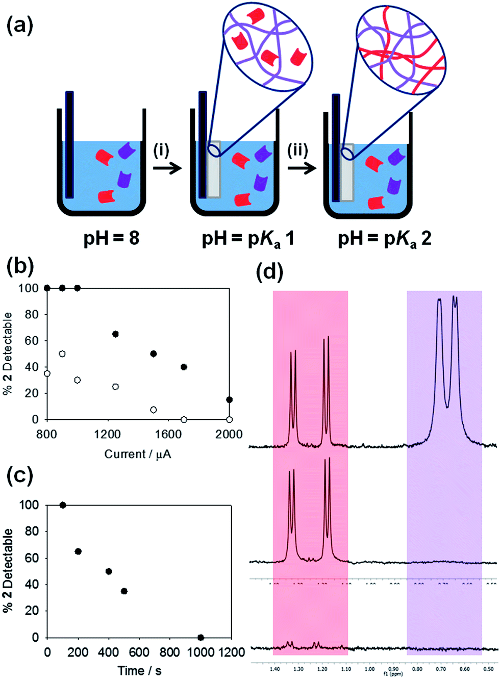 | ||
Fig. 3 (a) Schematic showing the sequential assembly of two LMWG in a multi-component system. (i) The LMWG with the highest pKa will assemble first as the pH is decreased, whilst the second LMWG will remain in solution until (ii) its pKa is reached. (b) Percentage of 2 detectable in the NMR spectrum of a gelled 1![[thin space (1/6-em)]](https://www.rsc.org/images/entities/char_2009.gif) :1 mixture of 1 and 2; gels formed at different currents for times of (●) 100 s and (○) 300 s. (c) Percentage of 2 detectable in the NMR spectrum of a gelled 1:1 mixture of 1 and 2; gels formed at a current of 800 μA for different times. (d) Partial NMR spectra for (top) stock solution of 1 and 2, each at a concentration of 0.5 wt% at pD 8 in D2O – the purple peaks are from the valine methyl peaks of 1 and the red peaks are from the alanine methyl groups on 2; (middle) application of a current of 1250 μA for 100 s results in loss of the peaks from 1 whilst 2 remains in solution; (bottom) application of a current of 2000 μA for 300 s results in the loss of peaks from both 1 and 2, showing that both have gelled. :1 mixture of 1 and 2; gels formed at different currents for times of (●) 100 s and (○) 300 s. (c) Percentage of 2 detectable in the NMR spectrum of a gelled 1:1 mixture of 1 and 2; gels formed at a current of 800 μA for different times. (d) Partial NMR spectra for (top) stock solution of 1 and 2, each at a concentration of 0.5 wt% at pD 8 in D2O – the purple peaks are from the valine methyl peaks of 1 and the red peaks are from the alanine methyl groups on 2; (middle) application of a current of 1250 μA for 100 s results in loss of the peaks from 1 whilst 2 remains in solution; (bottom) application of a current of 2000 μA for 300 s results in the loss of peaks from both 1 and 2, showing that both have gelled. | ||
Hence, we are able to both temporally and spatially gel different LMWG from a multi-component mixture. To exemplify this, we placed two slides within a solution containing both 1 and 2. Gels were grown in parallel, one at a current of 1250 μA for 100 s and the second at 2000 μA for 300 s. As expected from the data shown in Fig. 3b, the NMR spectrum of the gel grown at 1250 μA for 100 s showed only the presence of 2, demonstrating that the network comprised only LMWG 1, whilst the gel grown at 2000 μA for 300 s showed the presence of neither 1 nor 2, showing that both LMWG had assembled in this case (Fig. 3d). The bulk solution showed the presence of both 1 and 2, showing that no assembly had occurred in the bulk. To the best of our knowledge, this is the only example where such control over both the time of assembly and gel composition has been demonstrated for these low molecular weight gelators.
Conclusions
In conclusion, we have shown here the fine control that can be achieved by electrochemically triggering the gelation of LMWG. Not only can significant and useful amounts of gels be formed, but the composition of the gels can be controlled by judicious choice of the applied current and selection of the LMWG. It can easily be envisaged that through utilising LMWG with specific structures, this methodology could easily be adopted to prepare gels with specific guided tracks for cell alignment for example. Indeed, it is possible to prepare gels directly in cell culture medium using this technique (data not shown), implying that there will be significant utility of this approach. The degree of control over composition in a multi-component system has the potential to generate systems with specific regions of functionality or patterned surfaces, allowing materials with higher levels of complexity and information content. We have shown here a degree of spatial control, although using relatively large patterns. A challenge will be to develop these to smaller sizes where proton diffusion and subsequent dissolution may be too fast for effective gel formation, although we note that we have managed to use this electrochemical approach successfully for nanometre sized gels without issues over dissolution,16 providing care is taken over the relative pH of the bulk solution and the gels.Notes and references
- (a) D. Y. Ko, U. P. Shinde, B. Yeon and B. Jeong, Prog. Polym. Sci., 2013, 38, 672 CrossRef CAS PubMed; (b) S. Maude, E. Ingham and A. Aggeli, Nanomedicine, 2013, 8, 823 CrossRef CAS PubMed; (c) A. Doring, W. Birnbaum and D. Kuckling, Chem. Soc. Rev., 2013, 42, 7391 RSC.
- S. Van Vlierberghe, P. Dubruel and E. Schacht, Biomacromolecules, 2011, 12, 1387 CrossRef CAS PubMed.
- B. V. Slaughter, S. S. Khurshid, O. Z. Fisher, A. Khademhosseini and N. A. Peppas, Adv. Mater., 2009, 21, 3307 CrossRef CAS PubMed.
- (a) P. Terech and R. G. Weiss, Chem. Rev., 1997, 97, 3133 CrossRef CAS PubMed; (b) M. de Loos, B. L. Feringa and J. H. van Esch, Eur. J. Org. Chem., 2005, 3615 CrossRef CAS; (c) C. Tomasini and N. Castellucci, Chem. Soc. Rev., 2013, 42, 156 RSC; (d) N. M. Sangeetha and U. Maitra, Chem. Soc. Rev., 2005, 34, 821 RSC.
- (a) L. Chen, S. Revel, K. Morris and D. J. Adams, Chem. Commun., 2010, 46, 4267 RSC; (b) J. D. Tovar, Acc. Chem. Res., 2013, 46, 1527 CrossRef CAS PubMed; (c) H. X. Xu, A. K. Das, M. Horie, M. S. Shaik, A. M. Smith, Y. Luo, X. F. Lu, R. Collins, S. Y. Liem, A. M. Song, P. L. A. Popelier, M. L. Turner, P. Xiao, I. A. Kinloch and R. V. Ulijn, Nanoscale, 2010, 2, 960 RSC; (d) A. Dawn, T. Shiraki, S. Haraguchi, S. Tamaru and S. Shinkai, Chem.–Asian J., 2011, 6, 266 CrossRef CAS PubMed; (e) A. R. Hirst, B. Escuder, J. F. Miravet and D. K. Smith, Angew. Chem., Int. Ed., 2008, 47, 8002 CrossRef CAS PubMed.
- F. Rodriguez-Llansola, J. F. Miravet and B. Escuder, Chem.–Eur. J., 2010, 16, 8480 CrossRef CAS PubMed.
- J. Raeburn, A. Z. Cardoso and D. J. Adams, Chem. Soc. Rev., 2013, 42, 5143 RSC.
- L. E. Buerkle and S. J. Rowan, Chem. Soc. Rev., 2012, 41, 6089 RSC.
- (a) J. R. Moffat and D. K. Smith, Chem. Commun., 2009, 316 RSC; (b) A. R. Hirst, J. E. Miravet, B. Escuder, L. Noirez, V. Castelletto, I. W. Hamley and D. K. Smith, Chem.–Eur. J., 2009, 15, 372 CrossRef CAS PubMed; (c) W. Edwards and D. K. Smith, J. Am. Chem. Soc., 2013, 135, 5911 CrossRef CAS PubMed.
- (a) H. Aubin, J. W. Nichol, C. B. Hutson, H. Bae, A. L. Sieminski, D. M. Cropek, P. Akhyari and A. Khademhosseini, Biomaterials, 2010, 31, 6941 CrossRef CAS PubMed; (b) J. L. Charest, M. T. Eliason, A. J. Garcia and W. P. King, Biomaterials, 2006, 27, 2487 CrossRef CAS PubMed.
- J. Raeburn, T. O. McDonald and D. J. Adams, Chem. Commun., 2012, 48, 9355 RSC.
- T. J. Measey, B. N. Markiewicz and F. Gai, Chem. Phys. Lett., 2013, 580, 135 CrossRef CAS PubMed.
- A. Mata, L. Hsu, R. Capito, C. Aparicio, K. Henrikson and S. I. Stupp, Soft Matter, 2009, 5, 1228 RSC.
- R. J. Williams, A. M. Smith, R. Collins, N. Hodson, A. K. Das and R. V. Ulijn, Nat. Nanotechnol., 2009, 4, 19–24 CrossRef CAS PubMed.
- (a) Y. F. Wang, Y. Liu, Y. Cheng, E. Kim, G. W. Rubloff, W. E. Bentley and G. F. Payne, Adv. Mater., 2011, 23, 5817 CrossRef CAS PubMed; (b) Y. Liu, Y. Cheng, H. C. Wu, E. Kim, R. V. Ulijn, G. W. Rubloff, W. E. Bentley and G. F. Payne, Langmuir, 2011, 27, 7380 CrossRef CAS PubMed; (c) K. M. Gray, B. D. Liba, Y. F. Wang, Y. Cheng, G. W. Rubloff, W. E. Bentley, A. Montembault, I. Royaud, L. David and G. F. Payne, Biomacromolecules, 2012, 13, 1181 CrossRef CAS PubMed; (d) J. L. Terrell, T. Gordonov, Y. Cheng, H. C. Wu, D. Sampey, X. L. Luo, C. Y. Tsao, R. Ghodssi, G. W. Rubloff, G. F. Payne and W. E. Bentley, Biotechnol. J., 2012, 7, 428 CrossRef CAS PubMed; (e) Y. Cheng, C. Y. Tsao, H. C. Wu, X. L. Luo, J. L. Terrell, J. Betz, G. F. Payne, W. E. Bentley and G. W. Rubloff, Adv. Funct. Mater., 2012, 22, 519 CrossRef CAS; (f) J. Redepenning, G. Venkataraman, J. Chen and N. Stafford, J. Biomed. Mater. Res., Part A, 2003, 66A, 411 CrossRef CAS PubMed; (g) X. L. Luo, J. J. Xu, Y. Du and H. Y. Chen, Anal. Biochem., 2004, 334, 284 CrossRef CAS PubMed; (h) R. Fernandes, L. Q. Wu, T. H. Chen, H. M. Yi, G. W. Rubloff, R. Ghodssi, W. E. Bentley and G. F. Payne, Langmuir, 2003, 19, 4058 CrossRef CAS.
- E. K. Johnson, D. J. Adams and P. J. Cameron, J. Am. Chem. Soc., 2010, 132, 5130 CrossRef CAS PubMed.
- Y. Liu, E. Kim, R. V. Ulijn, W. E. Bentley and G. F. Payne, Adv. Funct. Mater., 2011, 21, 1575 CrossRef CAS.
- (a) D. J. Adams, Macromol. Biosci., 2011, 11, 160 CrossRef CAS PubMed; (b) D. M. Ryan and B. L. Nilsson, Polym. Chem., 2012, 3, 18 RSC.
- (a) L. Chen, G. Pont, K. Morris, G. Lotze, A. Squires, L. C. Serpell and D. J. Adams, Chem. Commun., 2011, 47, 12071 RSC; (b) L. Chen, T. O. McDonald and D. J. Adams, RSC Adv., 2013, 3, 8714 RSC.
- (a) L. Chen, S. Revel, K. Morris, L. C. Serpell and D. J. Adams, Langmuir, 2010, 26, 13466 CrossRef CAS PubMed; (b) K. A. Houton, K. L. Morris, L. Chen, M. Schmidtmann, J. T. A. Jones, L. C. Serpell, G. O. Lloyd and D. J. Adams, Langmuir, 2012, 28, 9797 CrossRef CAS PubMed; (c) C. Tang, A. M. Smith, R. F. Collins, R. V. Ulijn and A. Saiani, Langmuir, 2009, 25, 9447 CrossRef CAS PubMed.
- Y. Cheng, X. Luo, J. Betz, S. Buckhout-White, O. Bekdash, G. F. Payne, W. E. Bentley and G. W. Rubloff, Soft Matter, 2010, 6, 3177 RSC.
- E. K. Johnson, L. Chen, P. S. Kubiak, S. F. McDonald, D. J. Adams and P. J. Cameron, Chem. Commun., 2013, 49, 8698 RSC.
- L. Chen, K. Morris, A. Laybourn, D. Elias, M. R. Hicks, A. Rodger, L. Serpell and D. J. Adams, Langmuir, 2010, 26, 5232 CrossRef CAS PubMed.
- D. J. Adams, M. F. Butler, W. J. Frith, M. Kirkland, L. Mullen and P. Sanderson, Soft Matter, 2009, 5, 1856 RSC.
- K. L. Morris, L. Chen, J. Raeburn, O. R. Sellick, P. Cotanda, A. Paul, P. C. Griffiths, S. M. King, R. K. O'Reilly, L. C. Serpell and D. J. Adams, Nat. Commun., 2013, 4, 1480 CrossRef PubMed.
Footnote |
| † Electronic supplementary information (ESI) available. See DOI: 10.1039/c3mh00150d |
| This journal is © The Royal Society of Chemistry 2014 |