Tailoring porosity in carbon materials for supercapacitor applications
L.
Borchardt
*ab,
M.
Oschatz
a and
S.
Kaskel
*a
aDepartment of Inorganic Chemistry, Dresden University of Technology, Bergstraße 66, D-01069 Dresden, Germany. E-mail: stefan.kaskel@chemie.tu-dresden.de
bInstitute for Chemical and Bioengineering, ETH Zürich, Wolfgang-Pauli-Strasse 10, CH-8093 Zurich, Switzerland. E-mail: lars.borchardt@chem.ethz.ch
First published on 4th November 2013
Abstract
Within the different available electrochemical energy storage systems, supercapacitors stand out due to their high power densities and ultra-long cycle life. Their key-components are the electrode materials where the charge accumulation takes place and therefore many different approaches for the synthesis of carbonaceous electrode structures with well-defined pore systems are available. This review focuses on different strategies for tailoring porous carbon materials from the micropore level, over mesopores to macropores and even external or inter-particular porosity. A wide range of materials such as activated carbons, templated carbons, carbide-derived carbons, carbon nanotubes, carbon aerogels, carbon onions, graphenes and carbon nanofibers are presented, always in relation to their pore structure and potential use in supercapacitor devices.
 L. Borchardt | Lars Borchardt (Görlitz, Germany, 1985) studied chemistry in Dresden and obtained his PhD in inorganic chemistry from the Dresden University of Technology in 2013 working on the development of new porous carbon and carbide materials for energy storage applications. He is now a postdoctoral researcher at ETH Zürich focusing on scale up aspects for catalyst design. |
 M. Oschatz | Martin Oschatz (Radebeul, Germany, 1987) studied chemistry at the Dresden University of Technology from 2006 to 2011 and received a B.Sc. in 2009 as well as a M.Sc. in 2011. He is currently a PhD student in the group of Prof. Dr Stefan Kaskel. In 2013, he carried out a research stay in the group of Prof. Gleb Yushin at Georgia Institute of Technology in Atlanta. Porous carbon materials for gas and energy storage applications are the main objectives of his research. |
 S. Kaskel | Stefan Kaskel received his PhD in Inorganic Chemistry from Tübingen University in 1997. He was a Postdoctoral Humboldt-Fellow with Professor J. D. Corbett at the Ames Lab (USA). In 2000 he joined the MPI for Coal Research (Mühlheim a.d. Ruhr), as a group leader. Since 2004 he has been a full Professor in Inorganic Chemistry at the Dresden University of Technology and in 2008 he was co-appointed at the Fraunhofer Institute for Material and Beam Technology as head of the CVD and thin film department. His research interests include synthesis and characterization of porous and nanostructured materials. |
Introduction
The increasing environmental pollution and the depletion of fossil fuels promote the mandatory development of alternatives to established energy storage systems such as coal, oil, or gas. Among them, batteries and electrochemical capacitors (also referred to as supercapacitors) are the key technologies that should store the green energy produced by solar, water, and wind energy technologies in stationary and portable devices.Batteries store energy due to faradaic processes but the kinetics of these chemical reactions limit the speed with which energy can be provided to the consumer.1 In contrast, in supercapacitors there is a purely physical charge accumulation based on the electrosorption of electrolyte molecules on the surface of a usually carbonaceous electrode material.2,3 Here, no electrochemical reactions take place resulting in very fast charge- and discharge rates with lifetimes of more than 1![[thin space (1/6-em)]](https://www.rsc.org/images/entities/char_2009.gif) 000000 cycles and very high power densities. However, these high power densities can only be accomplished if the electrolyte has fast access to the complete surface of the electrode material. This can be ensured either by lowering the particle size of the carbon material down to the nanometer scale or by introducing internal porosity.4,5 The size, geometry, and distribution of these pores significantly influence the final performance of the supercapacitor device. Many commercial carbons exhibit wormlike, narrow pores which is the bottleneck, especially at high current densities and fast charge- and discharge rates. This justifies the multiplicity of current attempts to tune the pore size of carbon materials on both, the micropore scale (dpore < 2 nm) and the mesopore scale (2 nm < dpore < 50 nm).6–9 The latter can serve as ion highways allowing for very fast ion transport into the bulk of the electrode material and therefore ensure high power densities.10 This is of particular importance if large electrolyte molecules such as ionic liquids are used.5 Furthermore, the large pores can host pseudocapacitive species resulting in additional capacitance contribution due to fast faradaic reactions and increase the energy performance of the supercapacitor device dramatically.2 But tailoring pore size is not only decisive in terms of rapid electrolyte diffusion; it influences the total capacitance of the material as well. The density and amount of ions that can be stored within a pore depends in a non-trivial way on the size of the micropores. There is no simple linear correlation between surface area and capacitance, but there is an optimal micropore size, which is different for each electrolyte system and at different voltage windows. Theoretical studies have revealed that there is importance not only for adjusting the micropore size, but also their uniformity if the capacitance of a material should be increased.11 Since many years especially hierarchically structured materials have been of particular interest.3 They exhibit micropores providing high surface areas on the one hand and secondary transport pore systems built-up by larger pores on the other hand. For that reason, many attempts have been made to introduce secondary mesopores into microporous carbons using activation and templating approaches.12 Likewise, micropores were inserted into mesoporous materials using etching approaches.13,14
000000 cycles and very high power densities. However, these high power densities can only be accomplished if the electrolyte has fast access to the complete surface of the electrode material. This can be ensured either by lowering the particle size of the carbon material down to the nanometer scale or by introducing internal porosity.4,5 The size, geometry, and distribution of these pores significantly influence the final performance of the supercapacitor device. Many commercial carbons exhibit wormlike, narrow pores which is the bottleneck, especially at high current densities and fast charge- and discharge rates. This justifies the multiplicity of current attempts to tune the pore size of carbon materials on both, the micropore scale (dpore < 2 nm) and the mesopore scale (2 nm < dpore < 50 nm).6–9 The latter can serve as ion highways allowing for very fast ion transport into the bulk of the electrode material and therefore ensure high power densities.10 This is of particular importance if large electrolyte molecules such as ionic liquids are used.5 Furthermore, the large pores can host pseudocapacitive species resulting in additional capacitance contribution due to fast faradaic reactions and increase the energy performance of the supercapacitor device dramatically.2 But tailoring pore size is not only decisive in terms of rapid electrolyte diffusion; it influences the total capacitance of the material as well. The density and amount of ions that can be stored within a pore depends in a non-trivial way on the size of the micropores. There is no simple linear correlation between surface area and capacitance, but there is an optimal micropore size, which is different for each electrolyte system and at different voltage windows. Theoretical studies have revealed that there is importance not only for adjusting the micropore size, but also their uniformity if the capacitance of a material should be increased.11 Since many years especially hierarchically structured materials have been of particular interest.3 They exhibit micropores providing high surface areas on the one hand and secondary transport pore systems built-up by larger pores on the other hand. For that reason, many attempts have been made to introduce secondary mesopores into microporous carbons using activation and templating approaches.12 Likewise, micropores were inserted into mesoporous materials using etching approaches.13,14
This review gives an overview on different strategies for tailoring pores in carbon materials from the micropore level with sub-Ångstrom accuracy, over small mesopores to macropores and even external or inter-particular porosity. It also focuses on strategies towards carbon materials with hierarchical pore architectures. The review may not address all materials studied for supercaps but rather gives examples in which cases pores of a certain size are needed. In this context, the potential and precision of each synthetic technique to tailor pores is discussed, always in relation to the function in a supercapacitor device.
Micropore tailoring
According to eqn (1), the capacitance (C) of a supercapacitor electrode mainly depends on the electrode specific surface area (A), which must be as high as possible, and the distance (d) between the adsorbed ions and the electrode surface. The latter should be minimized, while the dielectric constant (ε) is set by the used electrolyte.| C = (εA)/d | (1) |
Since the values of A and d are significantly influenced by the size of the micropores within the active material, a precise control about their structure is highly desirable. The groups of Gogotsi and Simon have reported that there is an increase in the capacitance when ions enter pores of a certain narrow size. It is believed that ions partially lose their solvent shell leading to a drastic lowering of the electrode-ion distance. The energy involved in this solvation–desolvation process is interpreted as the reversibly stored amount of energy, which accounts for the surprisingly high capacitance increase in materials where pore sizes fall below a certain value.15,16 Despite these significant findings, an “optimal” micropore size is not easily available because the actual energy density of the device also depends on parameters such as the ion size and operating voltage window according to eqn (2).11,17
| W = 1/2CU2 | (2) |
At a given pore size, the maximal energy density increases with increasing cell voltage and saturates at high voltages when no additional charge can be accommodated within the pore (Fig. 1A). This saturation energy density increases (high voltages) when the pores get larger since more charge can be stored. Therefore, at high voltages large pores are preferable (Fig. 1B). At low voltages however, the energy density is smaller for large pores because an electro-neutral zone is formed in the centre of the large pore, which does not contribute to stored charge (Fig. 1C).
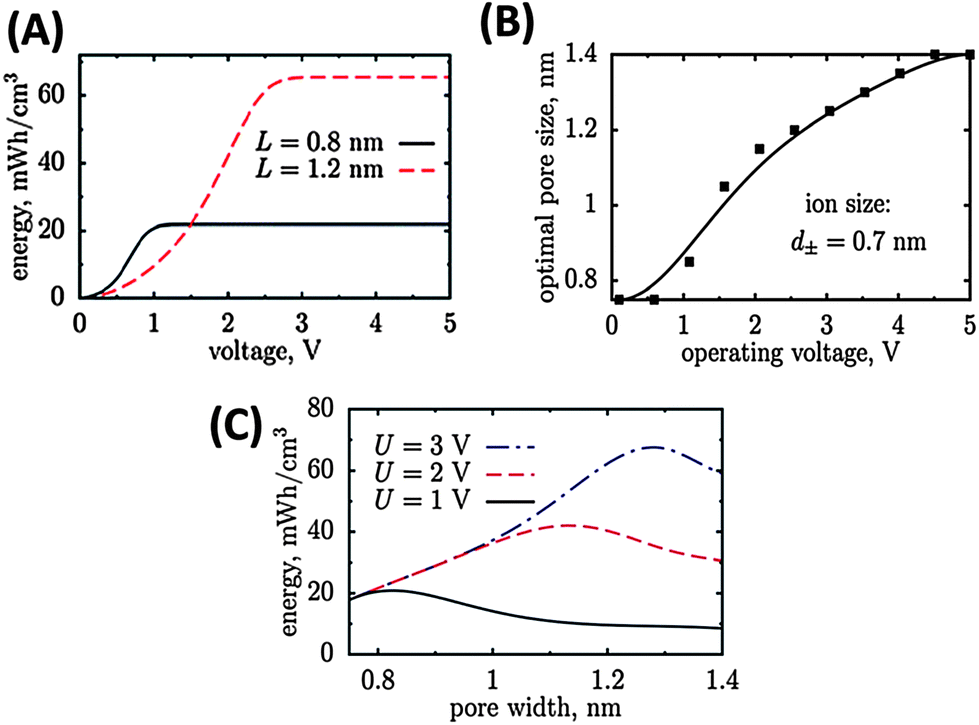 | ||
| Fig. 1 Energy density of carbon materials with different pore size depends on the potential window (A). The optimal pore size increases with increasing operating voltage window (B) and passes a maximum (C).11 Pictures are reprinted with permission from ref. 11. | ||
Excessive research has been performed on modeling and simulation of ion storage mechanisms in microporous carbon materials.11,18 These theoretical studies have revealed that the capacitance shows an oscillatory behavior when the pore size increases caused by changing interference of the two opposing electrical double layers in a theoretical slit pore.19 This encourages the synthesis of materials with very narrow pore size distributions (PSD) if the capacitance performance should be optimized. Beyond modeling and simulation, new experiments have been designed such as small-angle neutron scattering20 and nuclear magnetic resonance investigations (NMR)21–23 to directly probe the ion adsorption and electrosorption in microporous carbons. All of these studies impressively show the importance of uniformly adjusting the micorpore size in supercapacitor electrodes with low dispersity.
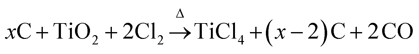
One of the most accurate synthesis strategies to control micropore size with sub-Ångstrom accuracy is based on the selective removal of metal atoms out of metal carbide matrices using gaseous halogens, primarily chlorine according to eqn (3).7
 | (3) |
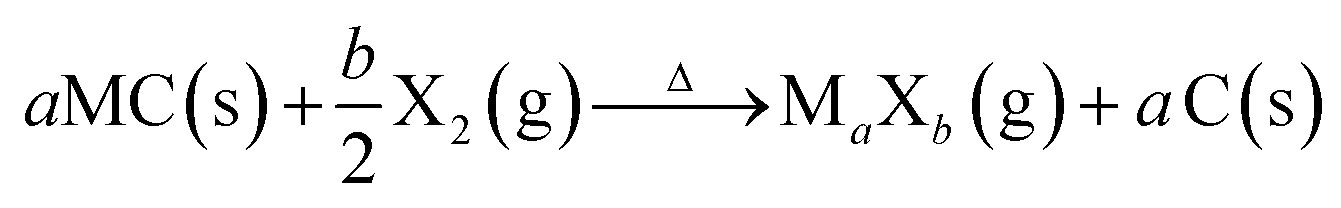
These materials are known as Carbide-Derived Carbons (CDCs). They exhibit bulk porosities of more than 50% and specific surface area exceeding 3000 m2 g−1.7,9 The extraction of metal atoms serves for the creation of micropores and takes place under full conservation of the original shape of the carbide allowing for a precise control over the resulting pore size, which is very sensitive to the used precursor. Accordingly, ternary carbides with low carbon concentration, such as Ti3SiC2, show a broad PSD with multiple maxima, while binary carbides such as SiC, TiC or TaC show a monomodal and narrow PSD (Fig. 2).24 Furthermore, the chlorination temperature has a significant influence on the PSD. Higher temperatures usually lead to an increase of the pore size due to the beginning of graphitization as a result of the self-organization of the highly mobile carbon atoms.25 These parameters mainly influence the genesis of pores in the micropore and small mesopore range and allow control over their diameter with sub-Ångstrom accuracy (Fig. 3).
 | ||
| Fig. 2 Influence of the carbide precursor structure on porosity of the corresponding carbide-derived carbon.7 Picture is reprinted with permission from ref. 7. | ||
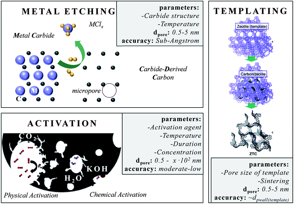 | ||
| Fig. 3 Different approaches for micropore insertion. The boxes summarize (i) the most important parameters that influence the pore size, (ii) the pore range and (iii) the accuracy this technique allows. | ||
Another important feature of CDCs for the use in supercapacitor applications is their comparably low content of oxygen-containing surface functional groups, such as carboxyl, carbonyl, or hydroxyl groups. In contrast to conventional activated carbons, the CDC surface is highly hydrophobic because these materials are produced in an oxygen-free atmosphere. This property is highly desirable for the use in supercapacitors because electrolytes containing organic solvent molecules or ionic liquids are highly incompatible with water. The latter strongly adsorbs in hydrophilic pores and therefore such carbons have to be dried prior to use as electrode materials which significantly contributes to the over-all cost of the device. Furthermore, oxidic functional groups may lead to unwanted non-faradaic side reactions even after drying.26
CDCs have widely been tested in supercapacitor applications. For instance, CDCs obtained by chlorine treatment of Ti2AlC and B4C precursors at 1000 °C showed specific capacitances of 175 F g−1 and 147 F g−1 when tested in aqueous H2SO4 electrolyte, respectively.27 Furthermore, TiC–CDC synthesized by Dash and co-workers shows a maximum specific capacitance of 130 F g−1 (115 F cm−3) in organic TEABF4/ACN electrolyte.28
The narrow and precisely controllable PSD of CDCs as well as their high purity is a huge advantage making them the materials of choice if supercapacitor mechanisms and electrolyte–carbon interactions are investigated.21–23 Recently, Forse et al. used a series of TiC–CDC materials with different pore sizes for static NMR investigations on the adsorption states of tetraethylammonium tetrafluoroborate (TEABF4) ions (1.5 molar, in acetonitrile) depending on the micropore diameters.29 From the chemical shifts in 11B spectra it was possible to clearly distinguish between ions strongly adsorbed in the narrow pores of the carbons and ions weakly adsorbed in larger mesopores or on the outer particle surface located in large reservoirs of the electrolyte. More importantly, the narrow and controllable micropore size distribution of the TiC–CDCs causes different chemical shifts of the 11B peak for the in-pore ions depending on the synthesis temperature since BF4− ions can enter larger pores (obtained by chlorination at 1000 °C) while they partially lose their solvent shell when adsorbing in the rather narrow micropores present in the CDCs prepared at lower temperatures (800 °C and 600 °C).23,29
Besides this CDC approach, templating is the method of choice if materials with uniform and ordered pore systems should be synthesized.3 This strategy is faced with the accusation of being expensive and badly up-scalable, but its academic benefit is non-questionable. Again, these materials are currently of outstanding importance since questions on electrolyte–carbon interaction or the principle influence of pore size/geometry/connectivity on supercapacitor performance need to be answered.23,30,31 The variety of templates32 is versatile and carbons with uniform micropore sizes are derived from different zeolite templates (e.g. Y, X13, beta, L, ZSM-5).33 If the zeolite channels are 3D-connected the replica carbon is even ordered. The specific surface areas of these carbons even exceed 4000 m2 g−1. Hence, it is not astonishing that zeolite X13-templated microporous carbons show capacitances of up to 300 F g−1 in aqueous electrolytes.3 In organic electrolytes, Yushin et al. reported capacitances of up to 146 F g−1 when zeolite Y templated carbons were used.34 Besides, layered structures such as pillared clays32 or 3D structures such as metal–organic frameworks (MOF) can serve as templates for microporous carbons as well.35,36
Chemical and physical activation of carbonaceous sources displays a comparably low-price technique to introduce new or to widen existing pores. Activated carbons (ACs) in general are obtained from the carbonization and subsequent activation of resources such as coals, fruit pits, peat, special woods, coconut shells and synthetic organic polymers. They are amorphous and their network is built-up by sp2 and some sp3 bonded carbon atoms, and also considerable quantities of heteroatoms such as nitrogen or oxygen. Indeed, the latter often reduce conductivity but increase wettability with aqueous electrolytes at the same time. The porosity of these carbons after carbonization is often not sufficient for supercapacitor application. The existing micropores often show slit, wormlike pore structures and broadly distributed pore sizes. This requires additional activation steps in order to create further pores, to widen existing pores or to modify the surface properties. However, these chemical and physical activation processes are only applicable to a certain limit since increasing pore extension is accompanied with the disadvantage of increasing material loss. The main activating agents are carbon dioxide, steam (both denoted as physical activation), potassium hydroxide, zinc chloride and phosphoric acid (denoted as chemical activation which requires an additional neutralization/washing step). All activation processes differ in the fraction of pore sizes they create.37,38
At the initial stage of CO2 activation for instance, the micropore and macropore volume increase coincide with proceeding burn-off. The widening of micro- to mesopores takes place only to a less extent and is accompanied by the ablation of the particle and a decrease in total pore volume when burn-off progresses. Steam activation also develops large amounts of micropores, but less macropores. It is a more selective etching agent and consequently produces a preferred widening of micropores towards mesopores as compared to CO2 activation. Physical activation with oxygen in turn, is highly exothermic and results in local overheating and non-uniform products.
In chemical activation processes the pore size can be controlled by changing the amount of the agent. Small amounts of ZnCl2 (<0.3 gZnCl2/gprecursor) for instance predominantly form micropores, while larger quantities (0.3–1 gZnCl2/gprecursor) form mesopores.37 If ZnCl2 and CO2 activation are compared, same amounts of microporosity are obtained by ZnCl2 with a higher carbon yield. This is generally observed, since all these agents act as dehydrating agents, stabilizing the carbon structure, giving higher carbon yields. The specific capacitances of the ACs strongly depend on the applied precursor and their interplay with the electrolyte. A summary of the electrochemical performances of ACs derived from renewable, natural precursors is listed in ref. 39. The best of them exceed capacitances of 300 F g−1 in aqueous electrolytes. But activation is not only suitable for natural carbon resources. The surface area of initially discussed CDCs can also be enhanced from 2200 m2 g−1 to more than 3000 m2 g−1 if an additional CO2 activation step is performed.40 Recent attempts use natural resources such as fungi as carbon precursors. Hierarchical carbons derived from KOH activation of these sources show surface areas exceeding 2000 m2 g−1 and very narrow micropores.41 If templated carbons such as the hexagonally ordered FDU-15 are KOH-activated the surface area increases from 600 to 1400 m2 g−1 and its capacitance even from 110 F g−1 to 200 F g−1 if measured in aqueous electrolytes.12
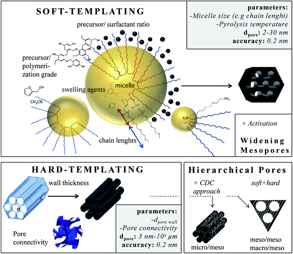
Small mesopore tailoring
Templating is the most accurate way to insert small mesopores and the method of choice if ordered pore structures are required. In principle, it can be subdivided into soft- and hard-templating. The latter is often denoted as nanocasting. Solid templates are used with well-defined pores acting as the placeholder for the final pore system. The hard templates, mostly nanoscaled silica materials, are infiltrated with carbon precursors (e.g. sucrose, furfuryl alcohol, phenolic resin, pitches, acetonitrile), which are then polymerized and finally carbonized. In most instances, subsequent removal of the template (e.g. silica by dissolution in hydrofluoric acid) is necessary, making this technique expensive, time-consuming and hardly up-scalable. However, the pores are very well-defined and the pore connectivity, morphology, and geometry can be controlled, if nanocasting is applied.42–45 The most prominent family of hard-templated carbons with high structural diversity is known as CMKs (Carbon Mesostructured by KAIST). They range from materials with pores in the lower mesopore scale that are introduced by templating of the ordered mesoporous silica MCM-48, yielding CMK-1 (cubic pore ordering, pores ∼3 nm) (Fig. 4A) to materials with larger pores that are observed if the larger KIT-6 template is used, yielding CMK-8 (cubic pore ordering, pores ∼5 nm). Changing the template structure from cubic (KIT-6) to hexagonal (SBA-15) provides carbons with hexagonally ordered pores named CMK-3. By coating only the walls of the template, tube-like mesoporous carbons, so-called CMK-5 (Fig. 4B), are obtained that exhibit two pore systems of 2 and 5 nm in size (comprehensive reviews can be found in ref. 6, 46 and 47). The final carbon pore size is adjusted precisely via the initial pore wall thickness of the silica template usually in the range of 2–14 nm if ordered mesoporous materials are considered.48 Many of these hard-templated ordered mesoporous carbons have been studied extensively regarding their electrochemical properties during the last decade. They show capacitances in the range of 100–200 F g−1 in aqueous electrolytes and up to 100 F g−1 in organic electrolytes.49–51 These days, their functionalization with pseudocapacitive species is of major significance in order to enhance the overall-capacitance.52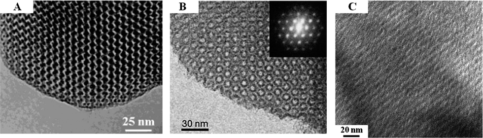 | ||
| Fig. 4 TEM images of (A) CMK-1 templated from cubic ordered MCM-48,53 (B) tubular structured CMK-5 templated from hexagonal ordered SBA-15,54 and (C) ordered mesoporous SiC–CDC synthesized by metal extraction of SBA-15-templated SiC.13 Pictures are reprinted with permission from ref. 13, 53 and 54. | ||
The soft-templating approach uses surfactants as structure-directing agents and carbon precursors (primarily based on resin) that interact with the surfactant and assemble around the formed micelles.3 Varying the surfactant/precursor ratio gives access to different mesostructures. In this approach the pore size can also be changed by changing the length of the hydrophobic chains of the surfactants. For example, the pore size can be increased from 2.8 nm to 4.3 nm if the hydrophobic chain length is enlarged from (EO132PO50EO132) to (EO106PO70EO106) (Fig. 5).3
 | ||
| Fig. 5 Different approaches for small mesopore generation. The boxes summarize (i) the most important parameters that influence the pore size, (ii) the pore range and (iii) the accuracy this technique allows. | ||
Reducing the synthesis temperature and applying swelling agents can further increase the micelle size and thus the carbon pore size.19 Furthermore, the size of the carbon precursor and its pre-polymerization degree determine the final pore size, either the precursor assembles with the hydrophilic chains giving small mesopores (2–5 nm) or if it is larger, it assembles around the chains giving larger pores (<6 nm). Very large mesopores (>20 nm) are accessible using special high-molecular surfactants such as polystyrene-blockpoly-(4-vinylpyridine) or poly(ethylene oxide)-polystyrene diblock copolymers. A comprehensive overview about the direct synthesis of ordered mesoporous carbon can be found within ref. 55. In addition, the pore symmetry (cubic, hexagonal, wormlike)56 as well as the pore connectivity57,58 can be controlled leading to advanced ion transport properties.
The final pore size can further be changed if additional activation steps are conducted. Activation of templated ordered mesoporous carbons with CuO widens the pores from 3.2 nm to 5.5 nm under conservation of the ordered pore structure. In organic electrolytes these materials show capacitances of 78 F g−1.59 Chemical activation of soft-templated carbons with KOH increases the surface area and therefore the capacitance to values as high as 200 F g−1 in aqueous electrolytes.12 Templated carbons are primarily amorphous and often badly conductive. In consequence, conducting additives such as nanotubes or carbon black are added if these materials are applied in supercapacitor applications.
In the last few years especially hierarchical materials of well-defined micro and mesopores are in a special focus. A very useful route to access them is to combine templating with the carbide-derived carbon approach.13,60 The synthesis of micro-mesoporous carbons starts with the synthesis of ordered mesoporous carbides by nanocasting of silica templates. Afterwards, these carbides serve as precursors for the metal atom extraction yielding hierarchical CDCs with ordered mesopores and well-defined micropores (Fig. 4C). As electrode material for supercapacitors, these materials show capacitances up to 170 F g−1 in organic, 185 F g−1 in ionic liquid, and more than 200 F g−1 in aqueous electrolytes. The hexagonally or cubic ordered mesopores act as ion-highways providing optimal transport of the electrolyte molecules through the bulk material. In consequence, these materials show a very low capacitance fade if high current densities up to 20 A g−1 are applied.5,10,14 Hierarchical meso–meso and macro–mesopore structures are accessible if soft-templating and hard-templating are organized together.55 The surfactant-assisted self-assembly of resins around “hard” polystyrene spheres yields hierarchical carbon with 10 nm pores and 60 nm windows and capacitances of 84 F g−1 in organic electrolytes.61 If biological templates such as crab shells are used, nanofibers with ordered mesopores of 11 nm and micrometer sized spaces in between the fiber arrays are obtained. These materials show specific surface areas as high as 1270 m2 g−1 and capacitances of 152 F g−1 in organic electrolytes.62 Hard- and soft-templating are the most common templating techniques,63 but emulsions are also suitable to introduce defined pores. Microemulsions allow the insertion of defined small mesopores (2–5 nm) by controlling the water/surfactant ratio and thus the size of the micelles.64
Large mesopore and macropore tailoring
Carbons with large mesopores (>10 nm) or even macropores are accessible using colloidal templates such as silica nanoparticles. These particles are either commercially available or can be synthesized using emulsion,65,66 spray pyrolysis67 or Stöber approaches.68 Carbon precursors, such as resins, acrylonitrile, pitches, or carbon hydrates first polymerize and then carbonize around the sol template structure followed by dissolution of the template. The final pore size is mainly determined by the silica particle size. One of the first large mesopore carbons (12 nm) obtained by colloidal templating was synthesized by Hyeon et al.69 But other parameters like the pH value, additional surfactants, and the sol/precursor ratio influence the size, distribution, and connectivity of pores as well.70 The pore size and the overall pore volume can further be controlled if only the particle surfaces are coated. Depending on the used amount of carbon precursor, different film thicknesses are achieved resulting in different porosities in the carbon replica.8Larger mesopores (20–50 nm) can be introduced if mesocellular silica foams (MCFs) are utilized as templates (Fig. 6A).71 By using a combination of nanocasting of MCFs and a CDC route, hierarchical micro- and mesoporous carbide-derived carbon mesofoams can be synthesized with specific surface areas up to 2700 m2 g−1 and pore volumes as high as 2.6 cm3 g−1. Important structural properties such as pore sizes and the degree of graphitization are precisely controllable by the elevated synthesis temperature. These materials show specific capacitances as high as 240 F g−1 in aqueous electrolytes. Their hierarchical pore structure causes extremely low capacity fading at high scan rates and high current densities and the large total pore volumes can host large amounts of active material making it an attractive candidate for use in battery electrodes.72 Hierarchical carbons with large mesopores (∼18 nm), additional small mesopores as well as micropores coupled with surface areas exceeding 2000 m2 g−1 were recently synthesized adopting the industrial Kroll-process.73 They are denoted as Kroll-Carbons (KCs) and synthesized by impregnating commercially available TiO2 nanoparticles with sucrose. After the carbonization of the sugar, chlorine gas is applied leading to the removal of the TiO2 template under the simultaneous insertion of micropores into the excess carbon framework according to eqn (4) (Fig. 7).
 | (4) |
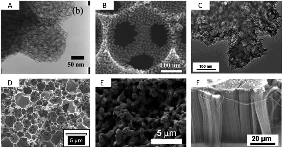 | ||
| Fig. 6 TEM/SEM images of (A) mesocellular carbon foam (dp = 20 nm),71 (B) macroporous carbon with mesoporous pore walls (dp = 317 nm, 10 nm),76 (C) micro/mesoporous Kroll-Carbon (dp = 18 nm, 1 nm),73 (D) micro/meso/macroporous carbon derived from High Internal Phase Emulsion (dp = 2 μm, 2.5 nm, 1 nm),74 (E) a carbon aerogel79 and (F) vertically aligned CNTs (dp ∼ 60 nm).89 Pictures are reprinted with permission form ref. 74, 76 and 89. | ||
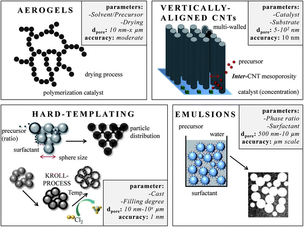 | ||
| Fig. 7 Different approaches for large mesopore and macropore design. The boxes summarize (i) the most important parameters that influence the pore size, (ii) the pore range and (iii) the accuracy this technique allows. | ||
This technique is useable for template particles of different sizes providing a versatile access to carbons of different mesopore sizes with different amounts of additional micropores (Fig. 6C). Due to the presence of such hierarchically structured pore systems combining high surface areas and pore volumes, Kroll-Carbons represent a promising class of carbon materials for use as electrode materials in supercapacitors.
High internal phase emulsions (HIPEs) allow for the introduction of large and interconnected macropores (1–10 μm).74 Again, if this technique is combined with a CDC approach it gives even access to trimodal pore systems (Fig. 6D). The walls of the open-cell foams contain micro- and mesopores of 1 and 2.4 nm sizes, respectively. This results in high nanopore volumes of 1.1 cm3 g−1 and specific surface areas as high as 2300 m2 g−1. Additionally, the distinctive macropore system of more than 7 cm3 g−1 in volume present in these materials offers rapid accessibility of the microporous walls. Post-synthesis carbon dioxide activation of this material can be applied to significantly increase the nanopore volumes (1.9 cm3 g−1) and specific surface areas (3000 m2 g−1) while the macropore system remains unaffected.40
Macroporous carbons are also synthesized using silica or polymer opal templates giving especially three-dimensional ordered carbon replicas. Here, the spherical pores are connected via small windows and the degree of interconnection depends on the precursor/template interaction, wettability and sintering processes during carbonization. A wide range of macropore sizes is possible.75 Hierarchical meso/macroporous carbons can either be synthesized if two hard-templates are combined, for instance using monomodal polystyrene and silica particles of different sizes, giving nm- and μm-sized carbons (Fig. 6B)76 or if hard- and soft-templating approaches are combined with each other.77 In the latter case the ordered mesoporous structure, dictated by a surfactant-assisted assembly, arranges around the package of silica particles giving the macropore structure. As Kanamura et al. showed, these bimodal carbons have specific surface areas as high as 1500 m2 g−1 if the smaller sacrificial silica templates are in the range of a few nanometers (5 nm). These materials show capacitances as high as 120 F g−1 in organic electrolytes.78
Carbon aerogels (Fig. 6E) are a class of macroporous open cell foams with very low mass densities and large pore volumes that are derived by sol–gel chemistry.79 A molecular precursor, often based on resorcinol, is cross-linked into a gel via polymerization. The resulting hydrogel displays a three-dimensional network of interconnected nanometer-sized particles. This material has to be dried under particular conditions such as supercritical drying or freeze drying. The arrangement and connectivity of the primary particles are influenced by catalyst parameters and reaction conditions and therefore dictate the final properties of the aerogel such as electric conductivity, pore size, surface area, or pore volume. Aerogels often exhibit large, broadly distributed and flexible macropores, accompanied by large pore volumes. The latter can be a drawback in supercapacitor applications because the low density limits the volumetric capacitance/energy density which is a general disadvantage of electrode materials containing large pores.80 An advantage of this sol gel approach however is the simple access to shaped materials such as monoliths or thin films avoiding the additional necessity for current collectors in the final supercapacitor device. Hierarchical aerogels are of certain relevance as well and are most often synthesized by combining this approach with templating or activation processes.
In the light of cost reduction it is straight-forward to synthesize porous carbons from abundantly available natural bio-resources or waste products that accumulate during agricultural production. The carbonization and subsequent chemical activation of wastes such as cow manure and pulp-mill sludge yielded, depending on activation steps and temperature, broadly distributed meso-/macroporous carbons with surface areas up to 700 m2 g−1 and pores around 25–100 nm.81 In recent years, the hydrothermal carbonization of natural carbon precursors was established as a very useful route for the production of carbon materials.82,83 This route can be applied to different types of organic materials such as algae, wood sawdust, starch, or cellulose.84 Nitrogen-doping of the resulting carbons can be achieved by using amino-containing biopolymers such as chitosan or D-glucosamine increasing the conductivity85 and therefore the performance in supercapacitor applications.86 Monolithic, flexible, sponge-like, carbonaceous aerogels have been synthesized applying a hydrothermal process to water melons. These materials have pores of approximately 45 nm and can be loaded with metal oxides resulting in high capacitive materials.87 The presence of heteroatoms within these materials has several advantages. Oxygen-rich carbons made from seaweeds, only possess low surface area around 200 m2 g−1 but comparatively high capacitance due to the oxygen functionalities that act in pseudo faradic charge/transfer reactions.88
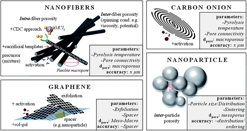
Carbon nanotubes with high aspect ratios that are arranged perpendicular to a substrate are known as vertically aligned carbon nanotubes (VA-CNTs) (Fig. 6F and Fig. 7).89 Their porosity matches with the distance between the single (but multi-walled) nanotubes and is therefore well-defined and controllable with the synthesis parameters. They can be synthesized by catalytic thermal chemical vapor deposition (CVD) either under atmospheric or vacuum conditions using a variety of carbon precursors such as acetylene, ethylene, or alkanes. The length of these primarily multiwalled nanotubes range from the μm to the cm-scale and their diameters are typically between 5 and 12 nm. They are promising for EDLC applications since they have very low internal resistance and already exhibit a binder-free contact with the current collector/substrate. The density, height, and diameter of the VA-CNTs can be adjusted by the composition, concentration, and particle size of the catalyst. The latter is primarily based on metal complexes of Fe, Co, Ni and Mo. But the structural morphology of the substrate also influences the diameter, density and alignment of the VA-CNT forest. The inter-tube distance can be decreased and adjusted after the synthesis by evaporation-induced densification.90 The electrochemically usable surface of a VA-CNT forest is mainly limited to the outer shell of the multiwall nanotubes, resulting in medium surface areas, generally <500 m2 g−1 (1315 m2 g−1 theoretical). The intertube distances depend on catalyst parameters but are usually in the mesopore range (∼60 nm) allowing good electrolyte diffusion. Recent efforts for scalable production of VA-CNT forests grown on an aluminum support (beneficial due to low mass density, high electrical conductivity and flexibility) showed capacitances of 65 F g−1 and very high power densities of approximately 80 kW kg−1. This is 1–2 magnitudes higher than the typical power density of supercapacitors made from activated carbon (AC) (0.5–10 kW kg−1) and is caused by the very low intrinsic resistivity and the good mass transport properties of these unidirectional intertube pores. These VA-CNTs are stable for more than 300000 cycles.89,91
External surface area and inter-particular porosity
As per definition a surface curvature is called a pore if its cavity is deeper than wide. This definition would exclude many nanostructured carbon materials that exhibit high surface areas and therefore qualify as supercapacitor materials. One straightforward approach is to lower the particle size of the carbon material down to the nanometer scale because the external specific surface area of a sphere increases with its decreasing diameter (Fig. 8).Gogotsi et al. applied the CDC approach on 30 nm sized TiC nanoparticles. The resulting carbon nanoparticles exhibit narrowly distributed micropores due to the metal extraction and additional widely distributed inter-particle mesopores.4 These materials can be synthesized at temperatures as low as 200 °C and various functional groups (C–H, C![[double bond, length as m-dash]](https://www.rsc.org/images/entities/char_e001.gif) O, C–O, and C
O, C–O, and C![[triple bond, length as m-dash]](https://www.rsc.org/images/entities/char_e002.gif) N) can be introduced – a feature which is not achievable by chlorination of micrometer-sized TiC particles. They show capacitances up to 150 F g−1 in aqueous electrolytes and no faradic surface reactions. Compared to CDCs obtained by chlorination of bulk carbides, the nanoparticles exhibit better electrochemical activity due to their high specific surface area and easily accessible micropores. Moreover, they show a comparable high degree of graphitization leading to improved power handling properties.
N) can be introduced – a feature which is not achievable by chlorination of micrometer-sized TiC particles. They show capacitances up to 150 F g−1 in aqueous electrolytes and no faradic surface reactions. Compared to CDCs obtained by chlorination of bulk carbides, the nanoparticles exhibit better electrochemical activity due to their high specific surface area and easily accessible micropores. Moreover, they show a comparable high degree of graphitization leading to improved power handling properties.
 | ||
| Fig. 8 Examples for carbon materials with large external surface areas. The boxes summarize (i) the most important parameters that influence the pore size, (ii) the pore range and (iii) the accuracy this technique allows. | ||
Monodisperse carbon spheres with adjustable size of 200–1000 nm are accessible via the Stöber-method.92 Without any further activation or modification, their external surface area is comparably low. They inspire in other applications, such as catalysis or drug delivery (Fig. 9).
A class of concentric, spherical, 5–10 nm sized, graphitic carbons is known as carbon onions (COs) (Fig. 8 and Fig. 9). The only relevant synthesis approach of these, in simple words multi-shell fullerenes, is based on vacuum annealing of nanodiamonds at temperatures above 1200 °C.93 COs are not intrinsically porous, but they have a fully accessible outer surface area of ∼500 m2 g−1 allowing for fast delivery of the stored energy. Because of the high degree of graphitization they have outstanding conductivities and are therefore relevant in high power density applications. Interdigital supercaps made of COs maintained a capacitance of 30 F g−1 at scan rates of 200 V s−1 which is more than three decades larger than common supercaps made from activated carbons. Their high conductivity and small size make them also suitable as conducting agents in electrochemical applications instead of carbon black or nanotubes. The relatively moderate capacitance of COs has recently been increased to 122 F g−1 by integrating pores into the outer CO shell.94 If added to the synthesis of templated carbons the resulting hybrid material benefits from their conductivity and the high capacitances and mesoporosity of templated carbons.
Advancing from nanoparticles to 1-D nanomaterials, carbon nanofibers offer large electrochemically accessible surface areas and interfiber porosity as well (Fig. 8 and Fig. 9). Besides conventional fiber production technologies like melt-spinning or melt-blowing, electrospinning of polymer solutions – primarily polyacrylonitrile (PAN) is a promising technology for synthesizing carbon fibers with diameters of few tens of nanometers to a few micrometers.95 For the preparation, the polymer solution is charged to a potential in the 10 to 30 kV range and ejected from the tip of a needle. The resulting polymer jet is accelerated and elongated while flying through the space and finally collected as an ultrathin fiber web on a counter electrode. With regard to supercap applications this technology is highly beneficial due to small fiber diameters and therefore short diffusion pathways, additional inter-fiber macroporosity, flexibility, self-standing, and the expandability of additional coating steps when processed to the final device. Surface areas of these webs are usually in the range of 500–2000 m2 g−1. The fiber pore structure can be adjusted by the pyrolysis regime only to a limited degree. Moreover, the interfiber macroporosity is not fixed because of the high flexibility of the fiber web. Micro- and mesopores are formed due to the evolution of volatile substances during pyrolysis (e.g., CO, CO2) and therefore largely depend on the used precursor. However, it is mainly the subsequent activation step that adds the majority of meso- and micropores.95 The most widely applied activation technique is based on steam. Pore insertion without activation is based on sacrificial templates such as Nafion96 or carbon precursor mixtures with different carbonization. An extensive summary on different carbon nanofibers for supercapacitor applications can be found in ref. 95. Most of the fibers show good capacitances in the range of 130–180 F g−1 in aqueous electrolytes. A capable strategy to enlarge the specific surface area and to better control the porosity in the nanofibers is to combine electrospinning with a carbide-derived carbon approach.97 For example, CDC nanofibers which are obtained after pyrolysis and chlorine treatment of a polycarbosilane precursor show surface areas as high as 3100 m2 g−1 with very narrowly distributed micropores (1 nm) and additional small mesopores of approx. 2.5 nm.98 Hierarchical fiber materials with large mesopores can be synthesized when starting from a TiCl4/resin precursor. The intermediate titania or titanium carbide nanoparticles that are formed after pyrolysis of this precursor are embedded in the carbon fiber matrix. Their extraction by a high temperature chlorine treatment allows controlling the accessibility and location of these mesopores (3–4 nm) within the resulting CDC fibers.99 Carbon nanofibers are hard to graphitize and suffer from low conductivity. Therefore, conductive agents such as CNTs or carbon black can be added to the electrospinning approach.
Likewise even though not strictly porous, graphene is a noteworthy electrode material as well (Fig. 8).100 Graphene is a single layer of sp2 hybridized carbon atoms in a two-dimensional honeycomb lattice.101 It is the basic building block for other carbon structures such as nanotubes, fullerenes and graphite. It stands out due to chemical stability and excellent electrical conductivity (zero-gap conductor). It is not a typical porous material, but rather an ideal flat surface with a high theoretical surface area of 2630 m2 g−1, which makes it a perfect model system for studying electrolyte double layer behavior in supercapacitors.101,102 Indeed, in theory graphene does not contain any wormlike, poorly accessible pores, but its layered structure can hinder electrolyte diffusion and mass transport. Therefore, graphenes with curved morphologies were synthesized by exfoliation.103 The reduction of graphene oxide introduces mesopore-like structures which allows for a better accessibility of especially large electrolyte molecules such as ionic liquids. But chemical activation with KOH also leads to significant increase in the surface area, additional mesopores of 2–5 nm and a better surface accessibility.104 Large micrometer-sized pores can be introduced if graphene layers are cross-linked in a sol–gel process resulting in a hydrogel (Fig. 9).105
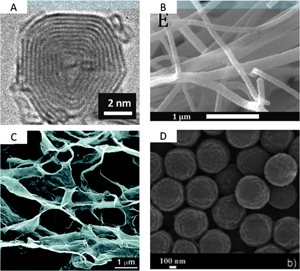 | ||
| Fig. 9 TEM/SEM images of (A) a carbon onion,93 (B) TiC–CDC nanofibers derived by electrospinning,99 (C) a graphene hydrogel,105 and (D) carbon spheres derived by the Stöber-method.92 Pictures are reprinted with permission from ref. 92, 93, 99 and 105. | ||
Composites of graphenes with other materials such as carbon spheres, vertically aligned nanotubes, carbon black or metal nanoparticles are also beneficial since these additives act as spacers and separate the sheets from each other. The resulting hierarchical materials show higher capacitances than the single components.106 Many groups report about capacitances in the range of around 150–250 F g−1.101,102,107 Recent attempts also use templates such as silica nanoparticles to introduce mesopores during CVD graphene synthesis. Finally it should be mentioned that currently many efforts are being made to dope graphenes with nitrogen to further increase the specific capacitance. Graphenes also enjoy the advantage of being utilized in ultrathin supercapacitors, printable electronics or nano-devices.
| Material | Activated carbon | Templated carbon | Carbide-derived carbon | Carbon aerogel | Carbon fiber | Graphene | VA-CNT | Graphene oxide |
|---|---|---|---|---|---|---|---|---|
| a Theoretical values. | ||||||||
| Price | Low | High | Medium | Medium | Medium | Medium | High | High |
| Scalability | High | Low | Medium | Medium | High | Medium | Low | Low |
| Surface area [m2 g−1] | ∼2000 | <4500 | <3200 | <700 | <200 | 2630a | 1315a | ∼500 |
| Conductivity | Low | Low | Medium | Low | Medium | High | High | Variable |
| Gravimetric capacitance | Medium | High | High | Medium | Low | Medium | Low | Low |
| Volumetric capacitance | High | Low | High | Low | Low | Medium | Low | Low |
Outlook
The run for ever-higher specific surface areas is not as constructive as it was regarded years ago and fades out since the upper theoretical limit seems reached. Therefore, many current studies confirm that especially the pore size is of major importance if the performance of carbons in supercapacitor applications should be increased. In addition, the benchmark-values for the individual materials in the supercapacitor application, in particular the capacitance, should be handled with care. Materials are not comparable with each other offhand just by looking on this value, it does not give an immediate insight which material is best for the desired application. Many questions must be answered prior to a material comparison: was the materials tested in a two or three electrode measurement? How was the device assembled? Was the capacitance obtained from cyclic voltammetry and at which scan rate or from galvanostatic measurements and at which current density and which part of the curve was evaluated? Which electrolyte should be used? Is the pore architecture or the material functionalization potentially more suitable for other electrolytes? Therefore, more profound in situ studies on the real charge storage mechanism, the electrolyte–carbon interaction and the true influence of the pore size on the overall performance are required. For that, model systems of carbons with uniform and well-defined pores are required and available by the synthesis techniques presented before. Moreover, it should never be overlooked that the volumetric capacitance of the materials are of extreme importance as well (Table 1). Material and packing densities should be as high as possible with regard to avoiding filling of too large intra- and inter-particular pores with the electrolyte. In many cases the volumetric or electrode area-related capacity of a material (in F cm−3 or F cm−2) is of particular interest for the actual supercapacitor application because the mass of the active material should be as high as possible when related to the mass of the whole device including the electrolyte, binder and current collector.In principle, any pore size can be adjusted and inserted into carbon, ranging from ultra-micropores to μm-sized macropores. It has been shown many times that the different approaches are largely compatible with each other, with the consequence that many hierarchical materials could be designed over the last few years. It is the authors' belief that these hierarchical hybrids are crucial to produce really advanced supercapacitor materials, not only in terms of hierarchical pore architectures but also in terms of combining the purely physical energy storage of an EDLC with the faradaic storage mechanism and to combine carbons and pseudocapacitive materials with each other.
The biggest challenge for carbon materials with well-defined pore sizes in supercapacitor applications is the reduction of price. No material could compete with the very low costs and the scalability of activated carbons so far. Nevertheless, the other carbon allotropes discussed in this paper often show better performances in the individual disciplines, and price of materials is often a matter of scale. Graphenes and carbon onions show better conductivities. The pore sizes of CDCs and templated carbons are more narrowly distributed. Aerogels and fibers can directly be fabricated into the desired electrode shape. VA-CNTs are orientated and perfectly connected to a current collector.
The authors only illuminated the importance of pore adjustment for supercapacitors in this paper. This is an important but highly focused area where porous carbons find an application. Pore adjustment is of equal significance in battery research, in separation and filtering issues, in drug delivery, cytokine adsorption, in catalytic support and gas storage applications. Moreover, it is worth mentioning that the carbon-based electrodes are only one part of the whole EDLC device and that the development of other parts and materials, such as advanced binding agents or separators are of comparable importance. In addition to the materials development, the use of environmentally friendly and low-cost manufacturing procedures for electrodes108 and devices is highly desired to further establish EDLCs in the market of rechargeable electrochemical energy storage devices. Last but not least, there is an ever-increasing interest in materials that can operate in aqueous electrolytes at high voltages with regard to increasing the energy density of supercapacitor devices operating in this high-conductivity, low-cost and environmentally friendly electrolyte system.109
Notes and references
- N.-S. Choi, Z. Chen, S. A. Freunberger, X. Ji, Y.-K. Sun, K. Amine, G. Yushin, L. F. Nazar, J. Cho and P. G. Bruce, Angew. Chem., Int. Ed., 2012, 51, 9994 CrossRef CAS PubMed.
- P. Simon and Y. Gogotsi, Nat. Mater., 2008, 7, 845 CrossRef CAS PubMed.
- Y. Zhai, Y. Dou, D. Zhao, P. F. Fulvio, R. T. Mayes and S. Dai, Adv. Mater., 2011, 23, 4828 CrossRef CAS PubMed.
- C. R. Perez, S.-H. Yeon, J. Segalini, V. Presser, P.-L. Taberna, P. Simon and Y. Gogotsi, Adv. Funct. Mater., 2013, 23, 1081 CrossRef CAS.
- M. Rose, Y. Korenblit, E. Kockrick, L. Borchardt, M. Oschatz, S. Kaskel and G. Yushin, Small, 2011, 7, 1108 CrossRef CAS PubMed.
- J. Lee, J. Kim and T. Hyeon, Adv. Mater., 2006, 18, 2073 CrossRef CAS.
- V. Presser, M. Heon and Y. Gogotsi, Adv. Funct. Mater., 2011, 21, 810 CrossRef CAS.
- K. P. Gierszal and M. Jaroniec, J. Am. Chem. Soc., 2006, 128, 10026 CrossRef CAS PubMed.
- Y. Gogotsi, A. Nikitin, H. Ye, W. Zhou, J. E. Fischer, B. Yi, H. C. Foley and M. W. Barsoum, Nat. Mater., 2003, 2, 591 CrossRef CAS PubMed.
- Y. Korenblit, M. Rose, E. Kockrick, L. Borchardt, A. Kvit, S. Kaskel and G. Yushin, ACS Nano, 2010, 4, 1337 CrossRef CAS PubMed.
- S. Kondrat, C. R. Perez, V. Presser, Y. Gogotsi and A. A. Kornyshev, Energy Environ. Sci., 2012, 5, 6474 CAS.
- Y. Lv, F. Zhang, Y. Dou, Y. Zhai, J. Wang, H. Liu, Y. Xia, B. Tu and D. Zhao, J. Mater. Chem., 2012, 22, 93 RSC.
- P. Krawiec, E. Kockrick, L. Borchardt, D. Geiger, A. Corma and S. Kaskel, J. Phys. Chem. C, 2009, 113, 7755 CAS.
- M. Oschatz, E. Kockrick, M. Rose, L. Borchardt, N. Klein, I. Senkovska, T. Freudenberg, Y. Korenblit, G. Yushin and S. Kaskel, Carbon, 2010, 48, 3987 CrossRef CAS.
- J. Chmiola, C. Largeot, P.-L. Taberna, P. Simon and Y. Gogotsi, Angew. Chem., Int. Ed., 2008, 47, 3392 CrossRef CAS PubMed.
- J. Chmiola, G. Yushin, Y. Gogotsi, C. Portet, P. Simon and P. L. Taberna, Science, 2006, 313, 1760 CrossRef CAS PubMed.
- C. Largeot, C. Portet, J. Chmiola, P.-L. Taberna, Y. Gogotsi and P. Simon, J. Am. Chem. Soc., 2008, 130, 2730 CrossRef CAS PubMed.
- C. Merlet, B. Rotenberg, P. A. Madden, P.-L. Taberna, P. Simon, Y. Gogotsi and M. Salanne, Nat. Mater., 2012, 11, 306 CrossRef CAS PubMed.
- G. Feng and P. T. Cummings, J. Phys. Chem. Lett., 2011, 2, 2859 CrossRef CAS.
- S. Boukhalfa, L. He, Y. B. Melnichenko and G. Yushin, Angew. Chem., Int. Ed., 2013, 52, 4618 CrossRef CAS PubMed.
- H. Wang, T. K. J. Koster, N. M. Trease, J. Segalini, P.-L. Taberna, P. Simon, Y. Gogotsi and C. P. Grey, J. Am. Chem. Soc., 2011, 133, 19270 CrossRef CAS PubMed.
- M. Deschamps, E. Gilbert, P. Azais, E. Raymundo-Pinero, M. R. Ammar, P. Simon, D. Massiot and F. Beguin, Nat. Mater., 2013, 12, 351 CrossRef CAS PubMed.
- L. Borchardt, M. Oschatz, S. Paasch, S. Kaskel and E. Brunner, Phys. Chem. Chem. Phys., 2013, 15, 15177 RSC.
- E. N. Hoffman, G. Yushin, T. El-Raghy, Y. Gogotsi and M. W. Barsoum, Microporous Mesoporous Mater., 2008, 112, 526 CrossRef CAS.
- Y. Gogotsi, R. K. Dash, G. Yushin, T. Yildirim, G. Laudisio and J. E. Fischer, J. Am. Chem. Soc., 2005, 127, 16006 CrossRef CAS PubMed.
- S. Osswald, J. Chmiola and Y. Gogotsi, Carbon, 2012, 50, 4880 CrossRef CAS.
- J. Chmiola, G. Yushin, R. K. Dash, E. N. Hoffman, J. E. Fischer, M. W. Barsoum and Y. Gogotsi, Electrochem. Solid-State Lett., 2005, 8, A357 CrossRef CAS.
- R. Dash, J. Chmiola, G. Yushin, Y. Gogotsi, G. Laudisio, J. Singer, J. Fischer and S. Kucheyev, Carbon, 2006, 44, 2489 CrossRef CAS.
- A. C. Forse, J. M. Griffin, H. Wang, N. M. Trease, V. Presser, Y. Gogotsi, P. Simon and C. P. Grey, Phys. Chem. Chem. Phys., 2013, 15, 7722 RSC.
- H. Nishihara, H. Itoi, T. Kogure, P.-X. Hou, H. Touhara, F. Okino and T. Kyotani, Chem.–Eur. J., 2009, 15, 5355 CrossRef CAS PubMed.
- A. Kajdos, A. Kvit, F. Jones, J. Jagiello and G. Yushin, J. Am. Chem. Soc., 2010, 132, 3252 CrossRef CAS PubMed.
- Y. Xia, Z. Yang and R. Mokaya, Nanoscale, 2010, 2, 639 RSC.
- H. Nishihara and T. Kyotani, Adv. Mater., 2012, 24, 4473 CrossRef CAS PubMed.
- C. Portet, Z. Yang, Y. Korenblit, Y. Gogotsi, R. Mokaya and G. Yushin, J. Electrochem. Soc., 2009, 156, A1 CrossRef CAS.
- B. Liu, H. Shioyama, H. Jiang, X. Zhang and Q. Xu, Carbon, 2009, 48, 456 CrossRef.
- B. Liu, H. Shioyama, T. Akita and Q. Xu, J. Am. Chem. Soc., 2008, 130, 5390 CrossRef CAS PubMed.
- F. Rodriguez-Reinoso and M. Molina-Sabio, Carbon, 1992, 30, 1111 CrossRef CAS.
- J. Wang and S. Kaskel, J. Mater. Chem., 2012, 22, 23710 RSC.
- L. Wei and G. Yushin, Nano Energy, 2012, 1, 552 CrossRef CAS.
- M. Oschatz, L. Borchardt, I. Senkovska, N. Klein, M. Leistner and S. Kaskel, Carbon, 2013, 56, 139 CrossRef CAS.
- J. Wang, A. Heerwig, M. R. Lohe, M. Oschatz, L. Borchardt and S. Kaskel, J. Mater. Chem., 2012, 22, 13911 RSC.
- Y. Liang, F. Liang, D. Wu, Z. Li, F. Xu and R. Fu, Phys. Chem. Chem. Phys., 2011, 13, 8852 RSC.
- Y. Liang, F. Liang, Z. Li, D. Wu, F. Yan, S. Li and R. Fu, Phys. Chem. Chem. Phys., 2010, 12, 10842 RSC.
- B.-H. Han, W. Zhou and A. Sayari, J. Am. Chem. Soc., 2003, 125, 3444 CrossRef CAS PubMed.
- D. Wu, Z. Li, Y. Liang, X. Yang, X. Zeng and R. Fu, Carbon, 2009, 47, 916 CrossRef CAS.
- C. Liang, Z. Li and S. Dai, Angew. Chem., Int. Ed., 2008, 47, 3696 CrossRef CAS PubMed.
- H. Yang and D. Zhao, J. Mater. Chem., 2005, 15, 1217 CAS.
- T.-W. Kim, F. Kleitz, B. Paul and R. Ryoo, J. Am. Chem. Soc., 2005, 127, 7601 CrossRef CAS PubMed.
- M. Sevilla, S. Alvarez, T. A. Centeno, A. B. Fuertes and F. Stoeckli, Electrochim. Acta, 2007, 52, 3207 CrossRef CAS.
- A. B. Fuertes, G. Lota, T. A. Centeno and E. Frackowiak, Electrochim. Acta, 2005, 50, 2799 CrossRef CAS.
- K. Jurewicz, C. Vix-Guterl, E. Frackowiak, S. Saadallah, M. Reda, J. Parmentier, J. Patarin and F. Beguin, J. Phys. Chem. Solids, 2004, 65, 287 CrossRef CAS.
- K. Pinkert, L. Giebeler, M. Herklotz, S. Oswald, J. Thomas, A. Meier, L. Borchardt, S. Kaskel, H. Ehrenberg and J. Eckert, J. Mater. Chem. A, 2013, 1, 4904 CAS.
- R. Ryoo, S. H. Joo, M. Kruk and M. Jaroniec, Adv. Mater., 2001, 13, 677 CrossRef CAS.
- S. H. Joo, S. J. Choi, I. Oh, J. Kwak, Z. Liu, O. Terasaki and R. Ryoo, Nature, 2001, 412, 169 CrossRef CAS PubMed.
- T.-Y. Ma, L. Liu and Z.-Y. Yuan, Chem. Soc. Rev., 2013, 42, 3977 RSC.
- G. Sun, J. Wang, X. Liu, D. Long, W. Qiao and L. Ling, J. Phys. Chem. C, 2010, 114, 18745 CAS.
- Y. Liang, D. Wu and R. Fu, Langmuir, 2009, 25, 7783 CrossRef CAS PubMed.
- Y. Liang, Z. Li, R. Fu and D. Wu, J. Mater. Chem. A, 2013, 1, 3768 CAS.
- C. Xue, Y. Lv, F. Zhang, L. Wu and D. Zhao, J. Mater. Chem., 2012, 22, 1547 RSC.
- L. Borchardt, M. Oschatz, M. Lohe, V. Presser, Y. Gogotsi and S. Kaskel, Carbon, 2012, 50, 3987 CrossRef CAS.
- H.-J. Liu, W.-J. Cui, L.-H. Jin, C.-X. Wang and Y.-Y. Xia, J. Mater. Chem., 2009, 19, 3661 RSC.
- H.-J. Liu, X.-M. Wang, W.-J. Cui, Y.-Q. Dou, D.-Y. Zhao and Y.-Y. Xia, J. Mater. Chem., 2010, 20, 4223 RSC.
- L. Borchardt, C. Hoffmann, M. Oschatz, L. Mammitzsch, U. Petasch, M. Herrmann and S. Kaskel, Chem. Soc. Rev., 2012, 41, 5053 RSC.
- L. Borchardt, F. Hasche, M. R. Lohe, M. Oschatz, F. Schmidt, E. Kockrick, C. Ziegler, T. Lescouet, A. Bachmatiuk, B. Buechner, D. Farrusseng, P. Strasser and S. Kaskel, Carbon, 2012, 50, 1861 CrossRef CAS.
- C. Solans, P. Izquierdo, J. Nolla, N. Azemar and M. J. Garcia-Celma, Curr. Opin. Colloid Interface Sci., 2005, 10, 102 CrossRef CAS.
- M. A. Lopez-Quintela, Curr. Opin. Colloid Interface Sci., 2003, 8, 137 CrossRef CAS.
- K. Okuyama and I. W. Lenggoro, Chem. Eng. Sci., 2003, 58, 537 CrossRef CAS.
- Y. Xia, B. Gates, Y. Yin and Y. Lu, Adv. Mater., 2000, 12, 693 CrossRef CAS.
- S. Han and T. Hyeon, Chem. Commun., 1999, 1955 RSC.
- S. Han, K. T. Lee, S. M. Oh and T. Hyeon, Carbon, 2003, 41, 1049 CrossRef CAS.
- J. Lee, K. Sohn and T. Hyeon, Chem. Commun., 2002, 2674 RSC.
- M. Oschatz, L. Borchardt, K. Pinkert, S. Thieme, M. R. Lohe, C. Hoffmann, M. Benusch, F. Wisser, C. Ziegler, L. Giebeler, M. Ruemmeli, J. Eckert, A. Eychmueller and S. Kaskel, Adv. Energy Mater., 2013 DOI:10.1002/aenm.201300645 , ahead of print.
- M. Oschatz, S. Thieme, L. Borchardt, M. R. Lohe, T. Biemelt, J. Brueckner, H. Althues and S. Kaskel, Chem. Commun., 2013, 49, 5832 RSC.
- M. Oschatz, L. Borchardt, M. Thommes, K. A. Cychosz, I. Senkovska, N. Klein, R. Frind, M. Leistner, V. Presser, Y. Gogotsi and S. Kaskel, Angew. Chem., Int. Ed., 2012, 51, 7577 CrossRef CAS PubMed.
- G. S. Chai, S. B. Yoon, J.-S. Yu, J.-H. Choi and Y.-E. Sung, J. Phys. Chem. B, 2004, 108, 7074 CrossRef CAS.
- G. S. Chai, I. S. Shin and J.-S. Yu, Adv. Mater., 2004, 16, 2057 CrossRef CAS.
- Y. Deng, C. Liu, T. Yu, F. Liu, F. Zhang, Y. Wan, L. Zhang, C. Wang, B. Tu, P. A. Webley, H. Wang and D. Zhao, Chem. Mater., 2007, 19, 3271 CrossRef CAS.
- S.-W. Woo, K. Dokko, H. Nakano and K. Kanamura, J. Mater. Chem., 2008, 18, 1674 RSC.
- J. Biener, M. Stadermann, M. Suss, M. A. Worsley, M. M. Biener, K. A. Rose and T. F. Baumann, Energy Environ. Sci., 2011, 4, 656 CAS.
- Y. Gogotsi and P. Simon, Science, 2011, 334, 917 CrossRef CAS PubMed.
- A. B. Namazi, C. Q. Jia and D. G. Allen, Water Sci. Technol., 2010, 62, 2637 CrossRef CAS PubMed.
- M.-M. Titirici and M. Antonietti, Chem. Soc. Rev., 2010, 39, 103 RSC.
- C. Falco, J. P. Marco-Lozar, D. Salinas-Torres, E. Morallon, D. Cazorla-Amoros, M. M. Titirici and D. Lozano-Castello, Carbon, 2013, 62, 346 CrossRef CAS.
- L. Wei, M. Sevilla, A. B. Fuertes, R. Mokaya and G. Yushin, Adv. Energy Mater., 2011, 1, 356 CrossRef CAS.
- L. Zhao, N. Baccile, S. Gross, Y. Zhang, W. Wei, Y. Sun, M. Antonietti and M.-M. Titirici, Carbon, 2010, 48, 3778 CrossRef CAS.
- L. Zhao, L.-Z. Fan, M.-Q. Zhou, H. Guan, S. Qiao, M. Antonietti and M.-M. Titirici, Adv. Mater., 2010, 22, 5202 CrossRef CAS PubMed.
- X.-L. Wu, T. Wen, H.-L. Guo, S. Yang, X. Wang and A.-W. Xu, ACS Nano, 2013, 7, 3589 CrossRef CAS PubMed.
- E. Raymundo-Pinero, F. Leroux and F. Beguin, Adv. Mater., 2006, 18, 1877 CrossRef CAS.
- S. Doerfler, I. Felhoesi, T. Marek, S. Thieme, H. Althues, L. Nyikos and S. Kaskel, J. Power Sources, 2013, 227, 218 CrossRef CAS.
- D. N. Futaba, K. Hata, T. Yamada, T. Hiraoka, Y. Hayamizu, Y. Kakudate, O. Tanaike, H. Hatori, M. Yumura and S. Iijima, Nat. Mater., 2006, 5, 987 CrossRef CAS PubMed.
- S. Doerfler, I. Felhoesi, I. Kek, T. Marek, H. Althues, S. Kaskel and L. Nyikos, J. Power Sources, 2012, 208, 426 CrossRef CAS.
- J. Liu, S. Z. Qiao, H. Liu, J. Chen, A. Orpe, D. Zhao and G. Q. Lu, Angew. Chem., Int. Ed., 2011, 50, 5947 CrossRef CAS PubMed.
- D. Pech, M. Brunet, H. Durou, P. Huang, V. Mochalin, Y. Gogotsi, P.-L. Taberna and P. Simon, Nat. Nanotechnol., 2010, 5, 651 CrossRef CAS PubMed.
- Y. Gao, Y. S. Zhou, M. Qian, X. N. He, J. Redepenning, P. Goodman, H. M. Li, L. Jiang and Y. F. Lu, Carbon, 2013, 51, 52 CrossRef CAS.
- M. Inagaki, Y. Yang and F. Kang, Adv. Mater., 2012, 24, 2547 CrossRef CAS PubMed.
- C. Tran and V. Kalra, J. Power Sources, 2013, 235, 289 CrossRef CAS.
- V. Presser, L. Zhang, J. J. Niu, J. McDonough, C. Perez, H. Fong and Y. Gogotsi, Adv. Energy Mater., 2012, 1, 324 Search PubMed.
- M. Rose, E. Kockrick, I. Senkovska and S. Kaskel, Carbon, 2009, 48, 403 CrossRef.
- J. R. Martin, L. Borchardt, M. Oschatz, G. Mondin and S. Kaskel, Chem. Ing. Tech., 2013, 85, 1742 CrossRef CAS.
- L. L. Zhang, R. Zhou and X. S. Zhao, J. Mater. Chem., 2010, 20, 5983 RSC.
- H.-J. Choi, S.-M. Jung, J.-M. Seo, D. W. Chang, L. Dai and J.-B. Baek, Nano Energy, 2012, 1, 534 CrossRef CAS.
- J. Hou, Y. Shao, M. W. Ellis, R. B. Moore and B. Yi, Phys. Chem. Chem. Phys., 2011, 13, 15384 RSC.
- W. Lv, D.-M. Tang, Y.-B. He, C.-H. You, Z.-Q. Shi, X.-C. Chen, C.-M. Chen, P.-X. Hou, C. Liu and Q.-H. Yang, ACS Nano, 2009, 3, 3730 CrossRef CAS PubMed.
- Y. Zhu, S. Murali, M. D. Stoller, K. J. Ganesh, W. Cai, P. J. Ferreira, A. Pirkle, R. M. Wallace, K. A. Cychosz, M. Thommes, D. Su, E. A. Stach and R. S. Ruoff, Science, 2011, 332, 1537 CrossRef CAS PubMed.
- Y. Xu, K. Sheng, C. Li and G. Shi, ACS Nano, 2010, 4, 4324 CrossRef CAS PubMed.
- H.-W. Wang, Z.-A. Hu, Y.-Q. Chang, Y.-L. Chen, Z.-Q. Lei, Z.-Y. Zhang and Y.-Y. Yang, Electrochim. Acta, 2010, 55, 8974 CrossRef CAS.
- D. A. C. Brownson, D. K. Kampouris and C. E. Banks, J. Power Sources, 2011, 196, 4873 CrossRef CAS.
- S. Thieme, J. Brueckner, I. Bauer, M. Oschatz, L. Borchardt, H. Althues and S. Kaskel, J. Mater. Chem. A, 2013, 1, 9225 CAS.
- V. Khomenko, E. Raymundo-Pinero, E. Frackowiak and F. Beguin, Appl. Phys. A: Mater. Sci. Process., 2006, 82, 567 CrossRef CAS.
| This journal is © The Royal Society of Chemistry 2014 |