
 Open Access Article
 This Open Access Article is licensed under a
 Creative Commons Attribution 3.0 Unported Licence
Inducing microscopic thermal lesions for the dissection of functional cell networks on a chip†
Philipp
Rinklin
a,
Dzmitry
Afanasenkau
b,
Simone
Wiegand
bc,
Andreas
Offenhäusser
ad and
Bernhard
Wolfrum
*ad
aInstitute of Bioelectronics (ICS-8/PGI-8), Forschungszentrum Jülich and JARA – Fundamentals of Future Information Technology, Forschungszentrum Jülich, 52425 Jülich, Germany. E-mail: b.wolfrum@fz-juelich.de
bInstitute of Complex Systems – 3 – Soft Condensed Matter, Forschungszentrum Jülich, 52428 Jülich, Germany
cChmistry Department – Physical Chemistry, University Cologne, D-50939 Cologne, Germany
dIV. Institute of Physics, RWTH Aachen University, 52076 Aachen, Germany
First published on 27th October 2014
Abstract
We present a versatile chip-based method to inflict microscopic lesions on cellular networks or tissue models. Our approach relies on resistive heating of microstructured conductors to impose highly localized thermal stress on specific regions of a cell network. We show that networks can be precisely dissected into individual subnetworks using a microwire crossbar array. To this end, we pattern a network of actively beating cardiomyocyte-like cells into smaller subunits by inflicting thermal damage along selected wires of the array. We then investigate the activity and functional connectivity of the individual subnetworks using a Ca2+ imaging-based signal propagation analysis. Our results demonstrate the efficient separation of functional activity between individual subnetworks on a microscopic level. We believe that the presented technique may become a powerful tool for investigating lesion and regeneration models in cellular networks.
Introduction
Over the past two decades, the development of lab-on-a-chip devices for biological or biomedical research has become a major aspect of interdisciplinary science at the interface of biology, chemistry, and physics.1 Lab-on-a-chip systems provide the possibility of massively parallelized experiments to achieve results with statistical significance and reduce material and time consumption. This is of particular value in biological research dealing with cells or cellular networks where the complexity of the investigated system generates intrinsically noisy data.2 Driven by advances in microfabrication technologies, the ability to manipulate cellular networks down to a single cell level has reached an unprecedented level.3,4 Recent examples demonstrate subcellularly resolved action potential recording,5 parallelized single-vesicle release measurements,6,7 or the high-throughput mechanical manipulation of individual cells.2Simplified cellular networks, such as small scale neuronal circuits, often serve as model systems in biological or biomedical research.8–10 The controlled generation of lesions in these model systems poses an important tool that helps to elucidate the functions of complex networks by disrupting their natural connectivity in defined locations.10 In this context, in vitro models of spinal cord injury are of particular clinical relevance as lesion studies conducted on these models may point towards effective therapeutic strategies for regeneration.10–14 Other common in vitro models of lesion and subsequent regeneration include wound assays induced by scratching15,16 or electrical means.17 In particular when read out electronically, these allow highly reproducible and quantitative data acquisition from biological model systems.17
A very common technique to generate highly resolved lesions in tissue models is laser-mediated ablation.18–21 A typical in vitro approach uses a laser, which is coupled to the beam path of a microscope and the target tissue or target cells are thermally destroyed by high energy deposition.22,23 This technique provides excellent flexibility since varying laser patterns can be implemented. However, microscope setups with coupled lasers require extensive alignment procedures and can be costly.23 Furthermore, the use of advanced cell analysis systems including microfluidic cell culture setups and intransparent functional substrates (e.g. silicon-based microscopic sensor arrays5) can make it difficult or impossible to integrate laser-based stimulation.
Recent research has sought to combine the precise generation of highly resolved lesions with the advantages of lab-on-a-chip techniques.13,24–29 To this end, microfluidic techniques have been effectively applied to induce lesion sites in models of axotomy.30–34 However, while allowing for high sample numbers by means of parallelization, these systems intrinsically impose certain constraints. Due to the flow-based nature of microfluidic systems, intersecting or orthogonal lesion patterns are difficult to realize. Furthermore, the generation of local lesions without otherwise constraining the culture's growth is problematic. An ideal solution to this problem is given by the direct integration of a reliable lesion-inducing method into the surface of the chip, which is used for cell culture.
Here, we present the application of microwire crossbar arrays for the introduction of localized thermal lesions to on-chip cell cultures. The arrays consist of two orthogonal layers of microwires that are structured and isolated using standard microfabrication technology (see Fig. 1b and c). When passing an electrical current through a given set of wires, resistive heating causes a temperature increase in the wires. Similar to electrocautery used in medical operations,35,36 this increase in temperature can be used to locally impose thermal stress on cells cultured directly on the chip (see Fig. 1a). We demonstrate the generation of highly resolved lesions and the dissection of small functionally separated subunits from a homogeneous cell network, making use of the microwire crossbar architecture.
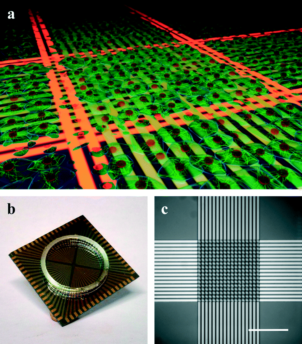 | ||
| Fig. 1 Microwire crossbar arrays for inducing localized thermal lesions. (a) 3D schematic of a localized thermal lesion experiment. Passing current through a set of wires (indicated in orange) leads to cell death in a confined region. (b) Photograph of an encapsulated microwire array chip (chip dimension: 2.4 × 2.4 cm2). (c) Photomicrograph of the actual microwire array consisting of two orthogonal layers of 17 parallel wires (scale bar: 150 μm). | ||
Results and discussion
Temperature distribution
In order to examine the thermal profile of the microwire arrays, fluorescence lifetime imaging microscopy (FLIM) was performed. In all experiments, a set of two neighboring wires was used, as the width of this set (24 μm) approximately corresponds to the lateral cross-section of a single cell. To evaluate the temperature distribution at the location of the cell layer, two horizontal or two vertical wires were supplied with 2 W each and the resulting temperature profiles were recorded in a focal plane 5 μm away from the chip's surface. Fig. 2 shows an exemplary thermograph of the chip with 2 W applied to the two left wires of the vertical set of wires (frame similar to Fig. 1c). The heated microwires result in temperatures of approximately 65 °C in the liquid above the active wires. The approximate cylindrical nature of the temperature profile, confines the region of elevated temperatures in direction normal to the chip surface to a few tens of micrometers. This low penetration depth thus limits the method to tissue models that are a single or a few cell layers in thickness. In the center region, the second layer of wires (extending along the y-axis) follows the topography of the first layer of wires (extending along the x-axis). This leads to an increased power density in this region and thus to a wider zone of temperatures above 55 °C (approx. 50 μm compared to 30 μm for the outer regions, which are not effected by wire intersections). The average temperature in the vicinity of the wires is increased to 45–50 °C. The high temperature region directly above the heated wires should thus induce cell death while, at short exposure times of a few minutes, the viability of the cells in the surrounding parts should not be affected.37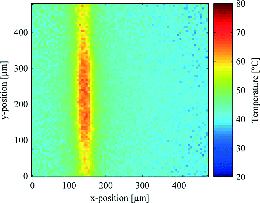 | ||
| Fig. 2 FLIM thermograph of the microwire array with 2 W of electrical power applied to the two left vertical wires (frame similar to Fig. 1c). | ||
Network dissection
A layer of HL-1 cells was grown on the crossbar arrays and thermal stimulation was applied to induce confined lesions on the cell network. To assess the inflicted lesions, fluorescent staining for live and dead cells was performed approximately 18 h after the lesion was inflicted. Exemplary fluorescence images for lesion along one, two, and four lines are shown in Fig. 3a–c, respectively (frames similar to Fig. 1c and 2). In each case 2 W were applied to a minimal set of 2 wires as described above. The current was applied in successive pulses of 1 min with a break of 1 min in between. For each set of wires, two pulses were used.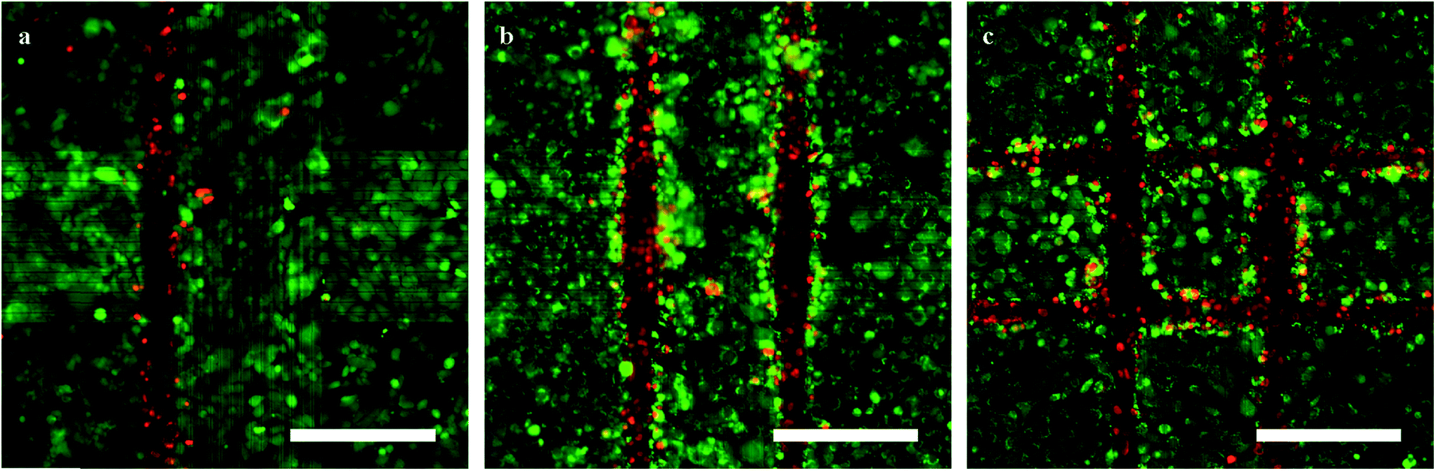 | ||
| Fig. 3 Fluorescence staining of HL-1 cells one day after lesion. (a–c) HL-1 cells stained with calcein (green, live cells) and EtHD (red, dead cells) after lesion on one, two, and four sides (a–c, respectively; scale bars: 200 μm; frames similar to Fig. 1c and 2). | ||
The fluorescence signal displayed in red, indicating dead cells, is limited to the area directly above the heated wires while the green fluorescence, showing live cells, is prevalent in the remaining parts of the culture. The red fluorescent dye used in the experiments was ethidium homodimer (EtHD), which stains the nuclei of dead cells. The green dye (calcein) selectively stains the cytoplasm of cells with an active metabolism. Comparing Fig. 2 and 3 it can be seen that cell death is limited to the high-temperature region determined in the FLIM experiments. The width of this region of dead cells was 43 ± 3.8 μm (n = 18) for the hottest parts of the wires, compared to 28 ± 3.3 μm (n = 18) over the cooler parts of the wires (see Fig. 2). Furthermore, the images show that the width of this region spans at least a single cell as intended to ensure successful dissection of the network on a functional level.
Signal propagation
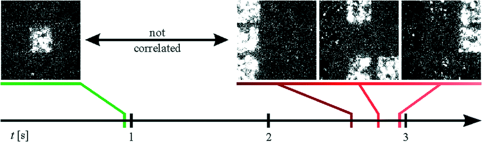
To evaluate the effect of thermally induced lesion on coordinated network activity, Ca2+ imaging and subsequent Ca2+ propagation analysis was performed. For these experiments HL-1 cells were chosen as a model system.38 These cells have been shown to be an excellent cardiac model for the study of action potential propagation as they spontaneously generate periodic action potentials.39–41 Furthermore, the electrical activity in cardiomyocytes is directly correlated with intracellular Ca2+ fluctuations.42 Intact Ca2+ propagation in the network is thus a good indicator of the general network activity. In order to visualize the Ca2+ propagation in the network, correlograms of the Ca2+ activity were calculated and plotted using digital video processing of the recorded fluorescence videos (a more detailed description of the data processing is given in the ESI†). To this end, the activity of the individual pixels in the fluorescence videos was evaluated. Pixels in regions of correlated activity were identified by the same color (either red or green) and inactive pixels were marked gray as shown in Fig. 4. Within the correlated regions, the brightness of the color reflects the signal delay, thus indicating the direction of signal propagation from dark to bright areas.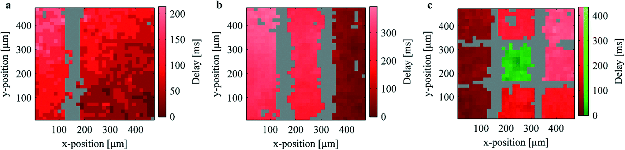 | ||
| Fig. 4 Ca2+ propagation analysis of HL-1 cultures after lesion (imaging was performed immediately after the lesion in the case of (a) and approx. 18 h after the lesion in the cases of (b) and (c)). Pixels with correlated activity are identified by the same color. Inactive pixels are displayed in gray. The relative signal delay within one group is shown by the brightness of the corresponding color. As can be seen, lesion along one or two parallel lines (a and b, respectively) retains connectivity in the network by peripheral coupling. However, lesions along two orthogonal pairs of lines (c), dissects a small subnetwork with uncorrelated activity (indicated in green). | ||
Fig. 4a–c show exemplary correlograms of HL-1 cultures after lesion on one, two, and four sides, respectively (compare Videos S1–S3†). In agreement with the temperature measurements and the live/dead staining (Fig. 2 and 3a, respectively), no Ca2+ activity could be detected along the heated wires (n = 35 in the case of single lesions). The surrounding network, however, displays Ca2+ propagation indicating a low effect on the biological functionality of these areas. As can be seen in Fig. 1b, the microwires widen in the peripheral parts of the chip. This causes the influence of the resistive heating to decrease in these areas and retains coupling in the larger network. The Ca2+ activity in the left and right part of Fig. 4a thus remains correlated after the lesion due to this peripheral coupling (see Fig. S4 in the ESI†).
To assess the lesion efficiency, only samples showing clear Ca2+ propagation were investigated (approximately 70% depending on culture status and passage number). In the experiments where a single lesion was inflicted, none of the samples showed activity at the lesion site, while 80% (n = 35) of the samples showed clearly separated propagation patterns on both sides of the lesion. The remaining 20% were either not successfully separated or displayed indeterminant propagation patterns. In combination, this indicates an effective destruction of the target tissue while maintaining the biological function of the surrounding cells. Similarly, in the case of a double lesion (Fig. 4b) no activity was detected along the heated wires while the surrounding network remains active. A large-scale signal propagation from right to left due to the peripheral coupling as well as propagation inside the individual active stripes can be seen.
In order to dissect functional subunits of the network, lesions were introduced on all four sides of the array (see correlogram in Fig. 4c). As in Fig. 4a and b, no activity can be seen over the heated wires and the outer parts retain correlated activity via peripheral coupling. The center square's activity, however, was not correlated with the outer sections of the network (see Video S3†). Fig. 5 shows exemplary frames from the Ca2+ imaging sequence of the sample shown in Fig. 4c. As can be seen, the center squares activity peaks at different times compared to the remaining squares. In addition to the propagation analysis, we investigated the activity of the individual regions in the frequency domain (compare Fig. S3†). As discussed in the ESI,† this analysis yielded differing frequencies and different periodicities in the case of a successful lesion. In summary, the results unequivocally show that the center square's activity is completely independent from that of the outer regions. Thus, we demonstrate the microscopic dissection of functionally autonomous subnetworks of less than 100 cells by localized heating using a substrate with an incorporated microwire crossbar array.
 | ||
| Fig. 5 Exemplary frames from the Ca2+ imaging sequence of the sample shown in Fig. 4c (frame size corresponds to approx. 466 × 466 μm2). While the center square has its peak intensity at approximately 0.9 s, all of the outer squares show activity between 2.6 and 2.9 s. | ||
Lesion parameters
In addition to the propagation analysis presented above, the effect of varying the electrical power used to heat the microwires was investigated. To this end, a series of pulses with increasing electrical power was applied to the samples. The duration of each pulse was 1 min and the pulses were separated by a break of 1 min. Corresponding Ca2+ imaging sequences were recorded during and in between the pulses and analyzed as described above. Fig. 6a shows the percentage of separated samples at a given time during the experiment (n = 26). A sharp increase in separated samples can be noted after applying 1.5 W to two neighboring wires. After the application of 2 W, more than 90% of the samples exhibit clearly separated propagation patterns.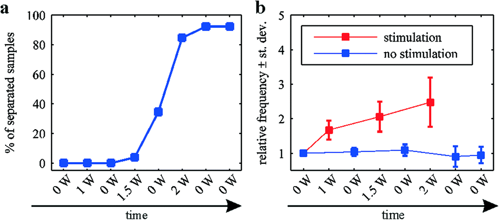 | ||
| Fig. 6 Effect of increasing electrical power on the separation efficiency and the frequency of the surrounding network's activity. (a) Percentage of separated samples during the sequential application of pulses of increasing electrical power. (b) Frequency of the Ca2+ activity in the surrounding of the lesion site during the sequential application of pulses of increasing electrical power. | ||
Fig. 6b shows the frequency of the surrounding network's Ca2+ activity. Since the frequency of the Ca2+ activity in HL-1 cells varies (depending on the sample, the passage number, etc.), the data were normalized with respect to the frequency before the application of any stimuli. A clear increase in the frequency can be seen during the application of electrical power. This increase becomes more pronounced with increasing electrical power. The induced heating of the peripheral regions (compare Fig. 2) causes an increase in the beating frequency as previously described.43 In between the stimuli, the network's activity returns to its original frequency, indicating the surrounding areas do not show signs of permanent cell damage.
Materials and methods
Chip fabrication
Microwire crossbar arrays were fabricated in the clean room using state-of-the-art microfabrication methods. Briefly, p-doped silicon wafers (Si-Mat Silicon Materials, Kaufering, Germany) were insulated by thermally growing 1 μm of silicon oxide under wet conditions. Subsequently, the first layer of wires (comprised of 17 wires with a width of 10 μm and an interwire spacing of 4 μm) was structured via photolithography using a double layer resist (LOR3B and NLOF2020, microresist technology, Berlin, Germany). After exposure and development (MIF326, microresist technology, Berlin, Germany), a metal stack of Ti/Al/Ti (15/300/10 nm in thickness, respectively) was deposited in a sputter deposition process (LLS Evo II, Oerlikon Systems, Balzers, Liechtenstein). An insulating stack of silicon dioxide/silicon nitride/silicon dioxide (100/50/100 nm in thickness, respectively) was then deposited using plasma enhanced chemical vapor deposition (Sentech Instruments GmbH, Berlin, Germany). After structuring the second set of microwires, a polyimide layer (PI-2610, HD Microsystems GmbH, Germany) was spin coated (6000 rpm, 30 s) to passivate the chip for cell culture conditions. To open the chip's contact pads, a single layer resist lithography (AZ-5340, AZ Electronic Materials GmbH, Wiesbaden, Germany) with subsequent wet chemical etching in AZ-326 (metal ion free, MicroChemicals, Ulm, Germany) and resist stripping in acetone was performed. The chip fabrication was then completed by gluing a glass ring to the chip using poly(dimethylsiloxane) (Sylgard 184, Dow Corning cooperation, Midland, USA).Thermography
Thermal images of the chips were recorded using fluorescence lifetime imaging microscopy (FLIM). To this end, approximately 20 μL of Rhodamine B (0.3 mg mL−1 in MilliQ) were encapsulated on the chip using silicon grease and a glass cover slip. The sample was then mounted in a laser scanning microscope (Olympus IX-71 with FV3-294 confocal unit and PicoQuant FLIM system) and the fluorescent decay data were recorded using a 485 nm laser and a long pass emission filter at 500 nm (HQ 500 LP, Leica Microsystems GmbH, Wetzlar, Germany). The data was preliminarily processed with the SymPho Time software (PicoQuant) to produce lifetime images. Subsequently, the temperature images were calculated from the lifetime images by means of custom Python scripts using a calibration curve from Müller et al.44Cell culture
Cardiomyocyte-like HL-1 cells were kindly provided by the Claycomb lab and cultured on the chips as follows: prior to culture, the chips were cleaned in 70% EtOH and dried with pressurized nitrogen. The inner area of the rings (compare Fig. 1b) was then incubated in a mixture of fibronectin (5 μg mL−1, Sigma) and gelatin (0.02 μg mL−1, Fischer Scientific) for approximately 60 min and rinsed once with bidistilled water. HL-1 cells were then plated to be confluent on the third day in vitro (DIV 3). The culture medium (Claycomb Medium purchased from JRH Biosciences supplemented with 10% fetal bovine serum, 100 U mL−1 penicillin, 100 μg mL−1 streptomycin, 2 mM L-glutamine purchased from Life Technologies, and 0.1 mM norepinephrine purchased from Sigma) was exchanged daily and the samples were incubated under physiological conditions (37 °C, 5% CO2).Thermal lesion and calcium imaging
Thermal stimuli were applied on DIV 2 in normal growth medium. The stimuli were applied using a home-built power supply operated by a custom LabView® software. This power supply was capable of applying voltages of up to 25 V per channel. The maximum current applicable per channel was approximately 200 mA. Concerning the average resistance of the individual wires of the array (approximately 50 Ω), this corresponds to a maximum applicable power of 2 W per channel. To reliably induce lesions, 2 W per wire were applied to two neighboring wires for 1 min. After a subsequent recovery time of 1 min, the application was repeated once. In the case of multiple lesion, the next stimulus was then applied in the same manner. Detailed information on the thermal profiles based on simulated data is given in the ESI.†Ca2+ imaging of the samples was performed on DIV 3. To this end, each sample was incubated with a calcium sensitive fluorescent dye (fluo-4 purchased from life technologies; working concentration 5 μM) for 15–30 min. The medium was then exchanged, the sample was transferred to the measurement setup, and Ca2+ imaging sequences of 1–2 min were recorded using an emCCD camera (ImagEMC9100-13, Hamamatsu Photonics Deutschland GmbH, Herrsching am Ammersee, Germany) coupled to an upright microscope (Zeiss Axiotech Vario, Carl Zeiss Microscopy GmbH, Göttingen, Germany). To filter the fluorescence of fluo-4, a BP 450–490 excitation filter was used in combination with an FT 510 beam splitter and a long pass emission filter at 515 nm (Zeiss Filter Set 9, Carl Zeiss Microscopy GmbH, Göttingen Germany).
Fluorescent staining
In order to stain for live and dead cells, calcein-AM and ethidium homodimer (purchased from life technologies) were used, respectively. The samples were stained according to the supplier's recommendations and the staining solution was exchanged for phosphate buffered saline after an incubation time of approximately 15 min. Fluorescent imaging was performed immediately after incubation using an AxioImager Z1 (Carl Zeiss Microscopy GmbH, Göttingen, Germany).Ca2+ imaging analysis
A detailed description of the data analysis is given in the ESI.† Briefly, each pixel's intensity trace was normalized by calculating (I − Imean)/Imean, where Imean represents the pixel's average intensity. Active pixels where then discriminated from inactive pixels by calculating each pixel's root-mean-square (rms) intensity. A binary mask of the active and inactive pixels was analyzed for connected regions to yield the patterns shown in Fig. 4. The intensity traces where then smoothed using a Gaussian filter with a width of 300 ms. For correlation analyses, each pixel was cross-correlated with the average intensity trace of its corresponding region. To find groups of regions with correlated activity, the average intensity traces of all regions where cross-correlated and regions with a correlation of more than 70% were grouped together. Each group of regions was then shifted to a common time scale using the cross-correlation of the average intensity traces of the group's individual regions.Conclusion
We presented the use of microwire crossbar arrays for inducing defined thermal lesions on cell networks in vitro. As an exemplary application, we dissected an active network of cardiomyocyte-like HL-1 cells into smaller autonomous subunits. Analyses of Ca2+ propagation patterns revealed the clear separation of functional activity in isolated subnetworks.We think that our approach will be useful for future investigations of functional cellular networks. In particular, it will be a powerful tool for studies of axotomy and subsequent regeneration.45 Here, our method can be used to cut axons grown across the microwires. Furthermore, we believe that the generation of lesions of variable width by using a varying number of wires is of benefit in the context of scratch wound assays. In combination with electronic read-out our method could allow automated studies of healing processes.
Apart from applying the crossbar architecture presented in this work, arbitary lesion patterns can be generated by modifying the geometry of the structured microwires. By locally varying the lateral dimension of the microwires, and thereby the electrical resistivity, it should be possible to limit the high temperature zones to certain parts of the wire facilitating short-segment or point-shaped lesions. The use of standard microfabrication technologies renders this concept easy to integrate into analytical chip-based platforms such as high-density microelectrode arrays. In addition, when using transparent materials such as indium tin oxide on glass wafers, our method can be directly combined with long-term imaging methods (e.g. genetically encoded calcium or voltage sensors combined with live-cell imaging).46,47 Combining the possibility to apply lesions to a given cell culture model with a parallel method for analyzing the network's response will enable high-throughput necessary for biological and biomedical studies.
Acknowledgements
We thank Norbert Wolters for building the power supply used in the lesion experiments, Marko Banzet for clean-room processing, and Vanessa Maybeck for help with the cell culture. We thank Prof. W. Claycomb for providing of HL-1 cells. Additionally, we acknowledge funding by the Helmholtz Young Investigators program.Notes and references
- A. van den Berg and P. Bergveld, Lab Chip, 2006, 6, 1266–1273 RSC.
- P. Tseng, J. W. Judy and D. Di Carlo, Nat. Methods, 2012, 9, 1113–1119 CrossRef CAS PubMed.
- A. Blau, Curr. Opin. Colloid Interface Sci., 2013, 18, 481–492 CrossRef CAS.
- M. E. Spira and A. Hai, Nat. Nanotechnol., 2013, 8, 83–94 CrossRef CAS PubMed.
- D. J. Bakkum, U. Frey, M. Radivojevic, T. L. Russell, J. Müller, M. Fiscella, H. Takahashi and A. Hierlemann, Nat. Commun., 2013, 4, 2181 Search PubMed.
- J. Wang, R. Trouillon and Y. Lin, Anal. Chem., 2013, 5600–5608 CrossRef CAS PubMed.
- A. Yakushenko, E. Kätelhön and B. Wolfrum, Anal. Chem., 2013, 85, 5483–5490 CrossRef CAS PubMed.
- C. E. Thomson, M. McCulloch, A. Sorenson, S. C. Barnett, B. V. Seed, I. R. Griffiths and M. McLaughlin, Eur. J. Neurosci., 2008, 28, 1518–1535 CrossRef CAS PubMed.
- J.-M. Peyrin, B. Deleglise, L. Saias, M. Vignes, P. Gougis, S. Magnifico, S. Betuing, M. Pietri, J. Caboche, P. Vanhoutte, J.-L. Viovy and B. Brugg, Lab Chip, 2011, 11, 3663–3673 RSC.
- S. Boomkamp, M. Riehle and J. Wood, Glia, 2012, 60, 441–456 CrossRef PubMed.
- J. Fawcett and R. Keynes, Annu. Rev. Neurosci., 1990, 13, 43–60 CrossRef CAS PubMed.
- M. C. Shearer, S. P. Niclou, D. Brown, R. A. Asher, A. J. G. Holtmaat, J. M. Levine, J. Verhaagen and J. W. Fawcett, Mol. Cell. Neurosci., 2003, 24, 913–925 CrossRef CAS PubMed.
- B. Vahidi, J. W. Park, H. J. Kim and N. L. Jeon, J. Neurosci. Methods, 2008, 170, 188–196 CrossRef CAS PubMed.
- I. B. Wanner, A. Deik, M. Torres, A. Rosendahl, J. T. Neary, V. P. Lemmon and J. L. Bixby, Glia, 2008, 56, 1691–1709 CrossRef PubMed.
- Z. Környei, A. Czirók, T. Vicsek and E. Madarász, J. Neurosci. Res., 2000, 61, 421–429 CrossRef.
- K. Pinco, W. He and J. Yang, Mol. Biol. Cell, 2002, 13, 3203–3217 CrossRef CAS PubMed.
- C. R. Keese, J. Wegener, S. R. Walker and I. Giaever, Proc. Natl. Acad. Sci. U. S. A., 2004, 101, 1554–1559 CrossRef CAS PubMed.
- C. I. Bargmann and L. Avery, Methods Cell Biol., 1995, 48, 225–250 CrossRef CAS PubMed.
- A. Vogel and V. Venugopalan, Chem. Rev., 2003, 103, 577–644 CrossRef CAS PubMed.
- M. Yanik, H. Cinar and A. Chisholm, Nature, 2004, 432, 822 CrossRef CAS PubMed.
- A. J. Canty, L. Huang, J. S. Jackson, G. E. Little, G. Knott, B. Maco and V. De Paola, Nat. Commun., 2013, 4, 2038 CAS.
- L. Soustelle, B. Aigouy, M.-L. Asensio and A. Giangrande, Neural Dev., 2008, 3, 11 CrossRef PubMed.
- S. T. Sweeney, A. Hidalgo, J. S. de Belle and H. Keshishian, Cold Spring Harb. Protoc., 2012, 2012, 726–732 Search PubMed.
- A. M. Taylor, S. W. Rhee, C. H. Tu, D. H. Cribbs, C. W. Cotman and N. L. Jeon, Langmuir, 2003, 19, 1551–1556 CrossRef CAS PubMed.
- P. S. Dittrich and A. Manz, Nat. Rev. Drug Discovery, 2006, 5, 210–218 CrossRef CAS PubMed.
- J. W. Park, B. Vahidi, A. M. Taylor, S. W. Rhee and N. L. Jeon, Nat. Protoc., 2006, 1, 2128–2136 CrossRef CAS PubMed.
- S. Guo, F. Bourgeois, T. Chokshi and N. Durr, Nat. Methods, 2008, 5, 531–533 CrossRef CAS PubMed.
- Y. Kim, K. Karthikeyan, S. Chirvi and D. P. Davé, Lab Chip, 2009, 9, 2576–2581 RSC.
- J. W. Park, H. J. Kim, M. W. Kang and N. L. Jeon, Lab Chip, 2013, 13, 509–521 RSC.
- A. Taylor, M. Blurton-Jones and S. Rhee, Nat. Methods, 2005, 2, 599–605 CrossRef CAS PubMed.
- I. H. Yang, R. Siddique, S. Hosmane, N. Thakor and A. Höke, Exp. Neurol., 2009, 218, 124–128 CrossRef CAS PubMed.
- A. M. Taylor, N. C. Berchtold, V. M. Perreau, C. H. Tu, N. Li Jeon and C. W. Cotman, J. Neurosci., 2009, 29, 4697–4707 CrossRef CAS PubMed.
- D. Kilinc, J.-M. Peyrin, V. Soubeyre, S. Magnifico, L. Saias, J.-L. Viovy and B. Brugg, Neurotoxic. Res., 2010, 19, 149–161 CrossRef PubMed.
- B. Deleglise, B. Lassus, V. Soubeyre, A. Alleaume-Butaux, J. J. Hjorth, M. Vignes, B. Schneider, B. Brugg, J.-L. Viovy and J.-M. Peyrin, PLoS One, 2013, 8, e71103 CAS.
- L. Malis, J. Neurosurg., 1996, 85, 970–975 CrossRef CAS PubMed.
- F. D. Sheski and P. N. Mathur, Clin. Chest Med., 1999, 20, 123–138 CrossRef CAS PubMed.
- O. Emohare, M. I. Hafez, A. Sandison, R. R. H. Coombs and I. D. McCarthy, Acta Orthop. Scand., 2004, 75, 610–617 CrossRef PubMed.
- W. C. Claycomb, N. A. Lanson, B. S. Stallworth, D. B. Egeland, J. B. Delcarpio, A. Bahinski and N. J. Izzo, Proc. Natl. Acad. Sci. U. S. A., 1998, 95, 2979–2984 CrossRef CAS.
- S. M. White, P. E. Constantin and W. C. Claycomb, Am. J. Physiol., 2004, 286, H823–829 CrossRef CAS PubMed.
- S. Pelloux, J. Robillard, R. Ferrera, A. Bilbaut, C. Ojeda, V. Saks, M. Ovize and Y. Tourneur, Prog. Biophys. Mol. Biol., 2006, 90, 270–298 CrossRef CAS PubMed.
- B. Hofmann, E. Kätelhön, M. Schottdorf, A. Offenhäusser and B. Wolfrum, Lab Chip, 2011, 11, 1054–1058 RSC.
- D. Bers, Nature, 2002, 415, 198–204 CrossRef CAS PubMed.
- L. Giovangrandi, K. H. Gilchrist, R. H. Whittington and G. T. A. Kovacs, Sens. Actuators, B, 2006, 113, 545–554 CrossRef CAS.
- C. B. Müller, K. Weiss, A. Loman, J. Enderlein and W. Richtering, Lab Chip, 2009, 9, 1248–1253 RSC.
- F. Bradke, J. W. Fawcett and M. E. Spira, Nat. Rev. Neurosci., 2012, 13, 183–193 CAS.
- B. J. Baker, H. Mutoh, D. Dimitrov, W. Akemann, A. Perron, Y. Iwamoto, L. Jin, L. B. Cohen, E. Y. Isacoff, V. A. Pieribone, T. Hughes and T. Knöpfel, Brain Cell Biol., 2008, 36, 53–67 CrossRef CAS PubMed.
- M. Mank and O. Griesbeck, Chem. Rev., 2008, 108, 1550–1564 CrossRef CAS PubMed.
Footnote |
| † Electronic supplementary information (ESI) available. See DOI: 10.1039/c4lc00805g |
| This journal is © The Royal Society of Chemistry 2015 |