Research highlights
Šeila
Selimović
ab,
Mehmet R.
Dokmeci
ab and
Ali
Khademhosseini
*abcd
aCenter for Biomedical Engineering, Department of Medicine, Brigham and Women's Hospital, Harvard Medical School, Cambridge, Massachusetts 02139, USA. E-mail: alik@rics.bwh.harvard.edu
bHarvard-MIT Division of Health Sciences and Technology, Massachusetts Institute of Technology, Cambridge, Massachusetts 02139, USA
cWyss Institute for Biologically Inspired Engineering, Harvard University, Boston, Massachusetts 02115, USA
dWorld Premier International – Advanced Institute for Materials Research (WPI-AIMR), Tohoku University, Sendai 980-8577, Japan
First published on 4th December 2013
Scaling laws: from human to human-on-a-chip
The development of medical drugs involves costly animal testing prior to conducting clinical trials in humans, but animal models often have significantly different cell physiology and hence these studies do not translate well to humans resulting in loss of time and resources.1 Hence, there is a great need for in vitro models of human tissues that represent the function of the human organism as a whole. Such platforms are an important focus of the current organ-on-a-chip research. Generating relevant human-on-a-chip models, however, relies not only on fabricating functional lab-on-a-chip devices, but also – and perhaps more importantly – on proper scaling of different tissues in terms of size and metabolic output.Takayama and colleagues have recently published a timely discussion of the different scaling principles in generating on-chip versions of various human tissues. In their work, Moraes et al.2 particularly focus on the effects of size vs. metabolic scaling of different organs. In the first – allometric – approach, all organs are scaled by the same factor, compared to the size of the complete organism, reflecting the assumption that the number of cells in an in vitro experiment is important. The authors contrast this approach to the BMR – basal metabolic rate – approach, which lends relevance to the metabolic output of a tissue. The model system in this study was adipose tissue, chosen for its relevance to diabetes and hypoglycemia; among others, adipose tissue uses insulin to control sugar levels in blood by converting glucose to lipids.
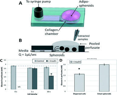
To experimentally evaluate the importance of appropriately selecting a scaling method, the authors created a simple microfluidic device, which housed adipocyte spheroids suspended in a collagen hydrogel (Fig. 1A). The tissue was then perfused with media and the metabolic product (perfusate) was collected (Fig. 1B) and analyzed with respect to glucose levels. In the control test (no insulin added to the media), the amount of glucose detected in the perfusate was almost constant, as expected, regardless of the number of cells in the adipose tissue (Fig. 1C). When insulin was added, the uptake of glucose in the adipose tissue increased slightly, which led to a small decrease in glucose levels in the perfusate. However, increasing the number of cells in the tissue by a factor of 10 led to a noticeable (almost 2-fold) decrease in detected glucose concentration. This observation indicated that appropriate scaling of tissues based on the number of cells should be considered in generating organ-on-a-chip models.
 | ||
| Fig. 1 Schematic of a microfluidic device for scaling experiments: angle (A) and side view (B). When exposed to insulin, the adipose tissue is enabled to uptake glucose, with more cells taking up more glucose (C). However, this is only true if the cells in the tissue are dispersed (D). Figure reprinted and adapted with permission from the Royal Society of Chemistry from Moraes et al.2 | ||
In a second experiment, adipocytes were confined to gel-encapsulated spheroids and compared to a case where the spheroids were mechanically dispersed within the gel. The tightly-packed structure of the cells inside intact spheroids prevents diffusion-based transport of nutrients and soluble factors to the spheroid core. In contrast, this transport limitation is removed when the spheroids are mechanically dispersed. The dispersed cells had better access to insulin, converting more glucose compared to the intact spheroids (Fig. 1D). In addition to scaling based on number of cells, this experiment illustrated that the arrangement of cells and shape of the in vitro tissue can also affect its metabolic behavior, and hence affects the scaling calculations and methods used in designing a human-on-a-chip.
It is clear that the scaling approaches necessary to generate functional human-on-a-chip platforms are complex, but the present study makes a convincing case for considering both organ size and metabolic behavior in the experimental design. In addition to this elucidating study, Moraes et al.2 also discussed ways to enable different scaling modes on-chip. For example, allometric scaling of multiple organs-on-a-chip may require some tissues to be impractically small or large. The BMR could then be adjusted by using media with different oxygen solubilities and different concentrations of key signaling molecules like insulin. The same approach could be used in cases where a particular device requires relatively low or high perfusion rates to provide adequate amounts of nutrients. Furthermore, the internal structure and its effect on the function of each organ should be considered in the selected scaling method in addition to the total number of cells. Namely, some tissues (e.g. endothelial, lung etc.) serve primarily for blood filtration or gas and molecular transport, and can therefore be considered functionally two-dimensional. Other tissues with storage or secretory functions such as fat and various glands are considered to be functionally three-dimensional. Hence, the size scaling itself is a complex problem and should be studied in more detail in the future.
Leaves as biomimetic templates for photocatalysis
Biomimetics is the field of engineering concerned with biological systems as models for novel devices and materials. Well-known examples include the hook and loop of Velcro tape, modeled after burrs; computer networks that are based on neuronal connections in the brain; and superhydrophobic or self-cleaning materials whose microscale architecture is similar to the surface of lotus leaves.3 Hence, biomimetic approaches are being utilized in a variety of research fields, from materials science to tissue engineering and chemistry. In chemistry in particular, there have been efforts in the last several decades to utilize knowledge of biological systems in order to develop more efficient chemical reactions.4More recently, biomimetic catalysis reactors are being merged with microfluidic technologies. For example, Koo and Velev have recently engineered a leaf-like structure, creating a laboratory version of the natural object that enables photoreaction inside its microscale channel network. In effect, the researchers introduced a microfluidic device, whose structure resembles that of natural leaves, to wick fluid through a photocatalyst-enriched material.5
There are three particular points of analogy between the natural and engineered leaves. First, water and minerals are transported inside a leaf through the capillary network termed venation. In comparison, fluid and molecules are distributed on-chip through the network of engineered microfluidic channels. Next, leaves are porous soft tissues containing water; similarly, the microfluidic device developed by Koo and Velev is filled with a porous agarose gel that is permeable to liquids. Last, the photosensitive areas of a leaf are uniformly distributed through the 3D tissue. This high surface-to-volume ratio is approximated on-chip by suspending photocatalytic TiO2 particles uniformly inside the hydrogel.
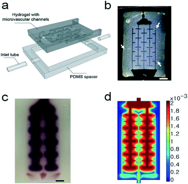
In their approach, the authors began with a suspension of the catalytic titanium dioxide particles in a heated agarose precursor gel. The gel was poured onto a master, then cooled to room temperature to solidify. In this fashion the master pattern was transferred to the gel, yielding a simple network of microfluidic channels. Subsequently, the hydrogel was sandwiched between two glass layers and surrounded by a PDMS spacer. Reagents were delivered to the hydrogel and removed through the fluidic ports (Fig. 2a). Importantly, the weight fraction of the agarose gel was relatively low (2%) to generate a highly porous matrix and optimize transport of liquids and reagents to the catalyst. The average pore size was 100 nm, which allowed the TiO2 particles (~330 nm diameter) to remain trapped inside the gel (Fig. 2b).
 | ||
| Fig. 2 Schematic of the microfluidic device, with the gel structure confined by the PDMS spacer to the space between two glass layers (a). Photograph of the hydrogel containing TiO2 particles inside the chip (b). The white arrows indicate areas with large TiO2 particle aggregates. Top view of the device filled with dyes 1 h after injection: photograph (c) and simulation results (d). Scale bars are 5 mm. Figure adapted and reprinted with permission from the Royal Society of Chemistry from Koo and Velev.5 | ||
To test the wicking properties of this device, the authors injected dye into it and observed its penetration into the gel for 1 hour. The liquid first entered the microfluidic channels and was then wicked into the porous agarose gel (Fig. 2c). This was in contrast to more common microfluidic device materials such as PDMS or glass, which are (almost) non-porous. To gain an understanding of the mass transport inside this hydrogel device, Koo and Velev also conducted a simulation (Fig. 2d), which corroborated the experimental results. Their results showed that the flux through the hydrogel was up to two orders of magnitude higher in the microchannel patterned device than inside a plain, unpatterned agarose gel. This was not surprising, considering that the Péclet number Pe (a ratio of convection to diffusion transport) ranged from 50 to 500 inside the channel, compared to only 1–5 inside the hydrogel.
To test the device as a catalytic microreactor, the researchers introduced two photosensitive dyes into the chip and exposed them to UV light. The dyes are known to degrade in the presence of titanium dioxide, when exposed to UV rays. The UV light caused the dyes to bleach within 40 minutes. In a control experiment that did not utilize TiO2 particles, the dyes did not lose their color. This observation served as evidence that TiO2 could be successfully used in this device as a catalyst.
A major advantage of the proposed reactor lies in the 3D distribution of the catalytic particles. Compared to microfluidic devices in which the catalyst is confined to a film on the channel walls, the biomimetic reactor maximizes the catalyst surface available to a reactant. This serves to accelerate the reaction and generate a more uniform distribution of the reaction product. In addition, the simple structure and operation of the device makes it readily available for scaling up into long, flexible ribbons or catalytically active sheets. The fact that the agarose gel did not (detectably) degrade throughout the experiment and the catalyst remained confined to the gel matrix further make this approach appealing for industrial applications, for reasons of long-term stability and environmental safety.
Real-time detection of drug–target interactions
A thorough understanding of molecular events such as drug–protein binding is important in numerous areas, including the detection of molecules and understanding the activity of drugs. Since direct optical methods are incapable of capturing the dynamics of a single molecule, researchers have utilized indirect approaches including surface plasmon resonance and ELISA to detect binding events. These methods, in addition to electrochemical measurements, can be utilized for real-time monitoring, but they are usually slow, requiring long preparation and response times, rely on bulky and expensive equipment, and offer limited sensitivity.6,7 Hence, the challenge lies in developing a high-precision detection instrument that offers real-time monitoring, while reducing sample incubation times and the supporting equipment infrastructure.To address this limitation, Zacharias and co-workers have recently developed a nanofluidic chip with a field effect transistor (FET) sensor.8 A FET consists of a conductive channel along which a current flows, while a potential difference is applied from one end of the channel (source) to the other end (drain electrode). The presence of a molecule on the channel surface alters the conductivity of the transistor, an event that can be captured by measuring the current through the device. Menzel et al.8 amplified this signal by building an array of very long (mm scale) but shallow (400 nm) parallel nanowalls on a wafer and biofunctionalizing them to enable binding and, ultimately, detection of bioactive molecules.
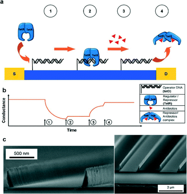
The nanosensor was fabricated on a silicon wafer coated with a dielectric (SiO2). Photolithography was used to generate an array of nanowalls across the entire wafer (Fig. 3c). Then, the semiconducting material ZnO was coated onto the chip through atomic layer deposition and reactive ion etching, such that it only remained on the vertical channel walls, but not the channel bottom. An additional Al2O3 film enhanced the stability of the zinc oxide layer. Electrodes were generated through vapor deposition of Al and Au. Finally, the nanosensor was placed on PDMS for isolation.
 | ||
| Fig. 3 Schematic of the antibiotic detection process on the ultralong nanowalls (a) and the corresponding conductance profile (b). The binding of the regulator molecule to the operator DNA is detected as a reduction in conductance of the nanowall structure (time point 1). In presence of an antibiotic, however, the regulator detaches from the operator, leading to an increase in conductance (time point 3). Time points 2 and 4 indicate washing steps. Cross-sectional images of the nanowalls (c). Figure reprinted with permission from the Royal Society of Chemistry from Menzel et al.8 | ||
The premise of the FET-based nanosensor was that binding or desorption of a negatively charged molecule on the semiconductor-coated nanochannel walls would modulate the surface charge on the walls. This change, in turn, could be detected as a difference in the conductance of the nanosensor. This premise was tested in a series of measurements of antibiotic concentrations in a solution. More specifically, the researchers added operator DNA to the channel walls, to which one particular regulator molecule (tetracycline repressor, TetR) could bind. In the presence of a buffer solution, binding of TetR led to a decrease in sensor conductance (Fig. 3a). Conversely, upon adding a particular antibiotic (tetracycline), TetR was cleaved, observed by an increase in sensor conductance (Fig. 3b). In addition, the amount of change in conductance could be correlated to the concentration of tetracycline in the sample.
The nanosensor was highly specific, only indicating a change in conductance for tetracycline binding events, even when a mixture of tetracycline and other antibiotics was present. This characteristic of the system was particularly useful in detecting tetracycline in food, a real-world application for the nanosensor. Here, organic cow milk was spiked with a known concentration of tetracycline, which is often given to animals to boost their health and milk production. The nanosensor was capable of detecting antibiotic concentrations on the order of 100 fM, a value several orders of magnitude below the European maximum allowable level (~200 nM). Independent ELISA testing confirmed the specificity and accuracy of the nanosensor results.
Aside from its high specificity and sensitivity, this nanosensor is noteworthy for its simple structure and ability to detect drug–target interactions in real time. These characteristics position the nanosensor as a candidate for scaling up in large-scale manufacturing, e.g. for point-of-care devices in the food and agricultural industries. In this case it would be worthwhile to study operator–regulator combinations for detection of common toxins in food products.
References
- D. Huh, Y.-S. Torisawa, G. A. Hamilton, H. J. Kim and D. E. Ingber, Lab Chip, 2012, 12, 2156–2164 RSC.
- C. Moraes, J. M. Labuz, B. M. Leung, M. Inoue, T.-H. Chun and S. Takayama, Integr. Biol., 2013, 5, 1149–1161 RSC.
- B. Bhushan, Philos. Trans. R. Soc., A, 2009, 367, 1445–1486 CrossRef CAS PubMed.
- R. Breslow, Chem. Soc. Rev., 1972, 1, 553–580 RSC.
- H.-J. Koo and O. D. Velev, J. Mater. Chem. A, 2013, 1, 11106–11110 CAS.
- K. J. Cash, F. Ricci and K. W. Plaxco, J. Am. Chem. Soc., 2009, 131, 6955–6957 CrossRef CAS PubMed.
- K. M. Mayer and J. H. Hafner, Chem. Rev., 2011, 111, 3828–3857 CrossRef CAS PubMed.
- A. Menzel, R. J. Gübeli, F. Güder, W. Weber and M. Zacharias, Lab Chip, 2013, 13, 4173–4179 RSC.
| This journal is © The Royal Society of Chemistry 2014 |
