 Open Access Article
 This Open Access Article is licensed under a
 Creative Commons Attribution 3.0 Unported Licence
Quantification of trace element contents in frozen fluid inclusions by UV-fs-LA-ICP-MS analysis
Moritz
Albrecht
*,
Insa Theresa
Derrey
,
Ingo
Horn
,
Stephan
Schuth
and
Stefan
Weyer
Institut für Mineralogie, Leibniz Universität Hannover, Callinstr.3, 30167 Hannover, Germany. E-mail: m.albrecht@mineralogie.uni-hannover.de
First published on 27th February 2014
Abstract
We have developed a new analytical setup for the determination of trace element concentrations in fluid inclusions by UV-fs-LA-ICP-MS. Laser ablation was performed at a low temperature of −40 °C by using a modified heating–freezing stage as the ablation cell. With this method it was possible to successfully analyse 53 of 55 frozen synthetic NaCl–H2O fluid inclusions in quartz, covering a size range between 8 μm and 25 μm down to a depth of 50 μm. The high success rate could be achieved as the 194 nm UV-fs-laser allows excellent control over the opening procedure of frozen fluid inclusions. Trace element analyses were performed with a fast scanning magnetic sector field ICP-MS. The lower limits of detection for fluid inclusion analysis vary from 0.1 μg g−1 (for 209Bi) to 10 μg g−1 (for 39K). The typical analytical uncertainty, depending on the element and respective concentration level, ranges between 10% and 30% (1RSD), based on the reproducibility of experimentally synthesized fluid inclusions. All elements from a stock solution, which behaved inert during the HP/HT experiments (B, K, Cd, Te, Tl, Pb and Bi), could be recovered in the synthetic inclusions at concentrations that correspond within their specific analytical uncertainties to their original concentration of 53 μg g−1. The method represents a highly efficient tool for the determination of accurate trace element data on low concentration levels in small fluid inclusions with a high success rate of >90%. The latter is particularly advantageous considering the commonly time consuming characterization of fluid inclusions.
1. Introduction
Fluid inclusion studies are commonly conducted in order to gain information about pressure–temperature conditions, and in particular about the chemical composition of deep crustal fluids.1 Concerning the latter, laser ablation inductively coupled plasma mass spectrometry (LA-ICP-MS) is regarded as the most reliable technique for the determination of concentrations of solutes in fluid inclusions for a large number of elements.2 This technique provides a high dynamic range which allows detecting elemental concentrations from the μg g−1 to the wt% level. Laser ablation-ICP-MS measurements can provide trace element concentrations (e.g. Cu, Zn, Au, Sn, Sr, Rb, Cs, Mo, Pb) as well as major element concentrations (e.g. Na, K, Ca, Mg) from small sample volumes of fluid inclusions from short transient signals acquired by ICP-MS.3 Even isotope ratio determinations have been carried out on fluid inclusions using this highly versatile technique.4 The basic principles for LA-ICP-MS analysis of fluid inclusions have been pioneered by Günther et al.5 using a nanosecond UV laser ablation system (193 nm, ArF excimer) in combination with a quadrupole ICP-MS (QMS). The method was refined during the last decade by Günther et al.,6 Halter et al.,7 Heinrich et al.3 and Allan et al.,8 but did not change in general. Besides the common determination of cation contents, it is also possible to quantify elements that exist as anions in the fluid inclusions, such as Cl, Br, and S.9,10High control over the laser ablation process is required to achieve representative fluid inclusion analysis. Problems can occur when fragments of the host mineral (most commonly quartz) quarry out during ablation and the fluid is lost through cracks before the ablation process reaches the inclusion. Other problems arise from incomplete mobilization of the inclusion, or the lack in mass spectrometric acquisition speed leading to an under-estimation of the elemental concentrations. In order to achieve representative analysis the complete volume of the inclusion, which may be composed of gas, liquid, and crystals, needs to be mobilized and transported to the ICP-MS.
Opening the inclusions is described as one of the most critical steps in fluid inclusion analysis.5 Especially the analysis of shallow inclusions (<10 μm depth) is often accompanied by uncontrolled release of the fluid inclusion content due to overpressure in the inclusions and splashing of the material out of the ablation pit (Fig. 1). Allan et al.8 estimated that the sampling process frequently controls the precision achieved for fluid inclusion analysis. Depending on their extent, most elemental concentrations can be determined with a precision on the order of 20–30% RSD. Better precision values have been reported for elements with high concentration levels (e.g. up to the wt%-range) in relatively large fluid inclusions.2 In this study, we focus on smaller inclusions with an elemental load of ≤53 μg g−1, which is of high significance for the chemical characterization of natural fluid inclusion but analytically challenging.
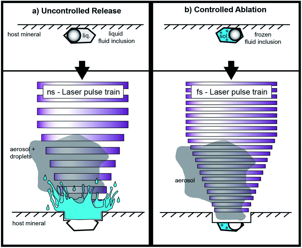 | ||
| Fig. 1 Comparative drawing of (a) UV-ns-LA of shallow fluid inclusions at room temperature and (b) UV-fs-LA of fluid inclusions with the freezing technique. The ablation of shallow fluid inclusions tends to lead to uncontrolled release of the fluid with UV-ns-LA, which results in unstable ICP-MS signals in this case. UV-fs-LA with frozen fluid inclusions ensures very high control on the opening of inclusions, which results in a higher success rate and very reliable data production from single fluid inclusion analysis. Illustration is not to scale. | ||
Quadrupole MS systems have been favoured over magnetic sector field mass spectrometers as they are capable of fast peak scanning which is essential for the sequential analysis of the transient signal that is typically generated during laser ablation analyses of fluid inclusions. Sweep times as short as 260 ms have been used for QMS analyses of a set of 20 isotopes.2 However, more recently fast scanning sector field mass spectrometers with a high transmission and a large dynamic detection range such as the Element XR™ from ThermoScientific™ have been developed. These are particularly suitable for short laser ablation analyses of low concentration levels.
Advantages of 196 nm UV-fs-LA over UV-ns-LA have been reported for the determination of isotopic ratios of heavy stable isotope systems11–14 as well as Pb–U mineral dating,15 but only preliminary experience has been documented for trace element analyses with single collector ICP-MS applications.2 To the best of our knowledge, only one study has been published using femtosecond laser ablation (fs-LA) for the analysis of fluid inclusions with respect to solute quantification. Borisova et al.16 used a NIR-fs-LA-QMS system in their study. Pettke et al.2 speculated that, particularly for fluid inclusion analysis with fs-LA, problems such as cracking at the crater bottom and associated material loss or phase explosions and an uncontrolled opening of the inclusion may arise. Nevertheless, the greatest advantage of fs-LA is the minimal heat transfer from the laser spot into the sample during ablation17 resulting in minimized elemental fractionation effects.15
In this study, we present a new analytical setup for the determination of major, minor and trace element concentrations in fluid inclusions. A 194 nm UV-fs laser is coupled with a fast scanning sector field ICP-MS. To use the low heat transfer of the fs-laser to its full capacity, we adapted a heating–freezing stage as the ablation cell and performed the ablations at low temperatures (e.g. −40 °C). This new approach was tested in this study by the analysis of different types of synthetic fluid inclusions with known concentrations.
2. Analytical conditions
2.1 Instrumentation
Analyses have been carried out with an Element XR™ fast scanning sector field inductively coupled plasma mass spectrometer (ThermoScientific™, Bremen, Germany) in combination with an in-house build laser ablation system which is based on a Spectra-Physics™ femtosecond (Ti:Sapphire) laser (Solstice™) operating in the deep UV at 194 nm. The laser system produces a pulse energy of 70–90 μJ in the fourth harmonic. This ultra short pulsed laser generates a soft ablation with high control and avoids elemental fractionation at the sample site. The ablations of the standard reference materials (NIST610) were carried out with a repetition rate of 10 Hz. For fluid inclusion analysis, the repetition rate was adjusted depending on the depth of the inclusions. For shallow inclusions, between near surface and 30 μm depth, a repetition rate of 2–5 Hz was used, resulting in signal intensities significantly above the respective detection limits (Table 1). Inclusions deeper than 30 μm were analyzed with 10 Hz for faster drilling. The laser repetition rate controls the signal shape, intensity and finally the limits of detection (LOD) for the measured elements. A higher repetition rate results in shorter and higher signals and subsequently in better LODs.2| Isotope | Background | 3SDbackground | SignalFlinc |
|---|---|---|---|
| 23Na | 1![[thin space (1/6-em)]](https://www.rsc.org/images/entities/char_2009.gif) 258057 258057 |
63932 |
4375165 |
| 88Sr | 1327 | 1306 | 7089 |
| 197Au | 113 | 205 | 728 |
The selected spot size on the sample surface is chosen to be bigger than the analyzed fluid inclusion in order to guarantee that the whole fluid inclusion is ablated and subsequently transported to the ICP-MS. An adjustable aperture in the beam path controls the spot size. It is possible to use spot sizes of up to 30 μm for the ablation of quartz. Ablations of quartz with bigger spot diameters would result in insufficient ablation rates, because of a reduced laser energy density. The spot size was held constant during the analysis which differs from the ablation procedure described by Günther et al.5 With our technique there is no need for stepwise opening of the inclusions, because an explosion of the inclusion or splashing of the material out of the ablation pit can be excluded when the inclusions are frozen. Especially the analysis of CO2 bearing inclusions are expected to be simplified since the pressure is stringly decreased upon phase transformation of CO2(gas) to CO2(solid). We expected that this approach works especially with femtosecond laser pulses due to their low thermal energy transfer, keeping even fluid inclusions with low ice melting temperatures (e.g. −65 °C) in their frozen state. The heat-affected zone during fs-LA has been investigated in earlier studies. Hirayama and Obara18 showed that the layer affected by heating with a femtosecond laser is only of a few nm thickness. In contrast, nanosecond laser ablation results in significant conductive heat transfer within a layer of several μm.19
For analyses, the Element XR™ is operated in “speed mode” which provides an optimized data acquisition for short transient signals as produced during LA of fluid inclusions. Due to a faster magnetic scanning and a faster scanning of the electrical field in the electrostatic analyzer unit, the sweep time is much shorter than that commonly used for analyses with sector field instruments. For 20 isotopes ranging between 9Be and 209Bi, one sweep takes 477 ms. A short sweep time is essential for fluid inclusion measurements, because the signal peak commonly occurs subsequent to the opening of the fluid inclusion (Fig. 2) and a slow data acquisition may result in a preliminary signal cut-off and artificially fractionated element concentrations. Further ICPMS operational settings are shown in Table 2.
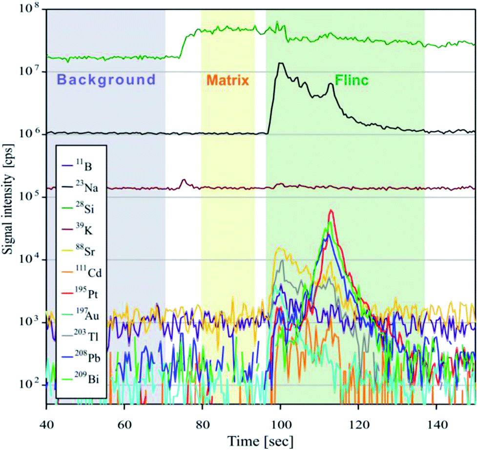 | ||
| Fig. 2 Fluid inclusion (“Flinc”) signal from analysis 19nov37 on sample ID189-Pt. Filled areas show the integration windows for background, matrix and inclusion signal chosen for data evaluation. The size of the inclusion was 21 μm in diameter, located at 20 μm depth. The laser repetition rate was 2 Hz. | ||
| Spectrometer | Element XR™ |
|---|---|
| RF power | 950 W |
| Carrier gas flow (He) | 0.27–0.3 L min−1 |
| Sample gas flow (Ar) | 0.9–1 L min−1 |
| Auxiliary gas flow | 0.65 L min−1 |
| Cool gas flow | 14.5 L min−1 |
| Cones | Ni “Jet” sampler |
| Ni “H” skimmer | |
| Dwell time | 0.003 s (0.01 s for Pt and Au) |
| Samples per peak | 100 |
| Mass window | 4% |
For this study, we used a modified heating–freezing cell for laser ablation in order to overcome some fundamental limitations of LA-ICP-MS analysis of fluid inclusions. One of the aims was to improve the fluid inclusion opening procedure and thereby avoid the explosive ejection of the material during opening. With frozen inclusions and the small ablation rate of the UV-fs laser, we aimed to enhance the control during the opening process and as a result to improve the success rate of fluid inclusion analyses.
While frozen, cracking at the bottom of the fluid inclusion would only result in the loss of gases, which are not frozen and cannot be detected with the instrumentation used. Furthermore, we expected that the transient signal could be stretched in time using low repetition rates and frozen solid fluid inclusion. Additionally, we aimed to improve the standardization process by using frozen matrix matched calibration standards prepared from standard solution in addition to the NIST610 and NIST612 glass standards. The matrix-matched standards enabled precise quantifications even at low counting rates. Independent of the external standard used, the precision of the analyses still depends on the size, shape and position of the inclusions, as well as on the laser repetition rate.
The analytical setup was realized with a modified ‘HCS622V’ cell from INSTEC™, Colorado, USA. The cell is vacuum tight and provides an appropriate cell window to sample distance suiting the use of an objective with a focal length of 20 mm. It provides precise temperature control over the range from −190 °C to +600 °C. To optimize the cell volume, the cell was modified to carry a removable 3 cm3 cell made from Teflon, which is sealed to the main cell by means of O-rings. The small cell connects to the gas inlet and outlet with Teflon tubes. With this modification the washout time is reduced dramatically. Helium, a gas with much higher thermal conductivity compared to Argon, can be used with flow rates of up to 0.8 L min−1 limiting the lowest reachable temperature to −100 °C. Without the small Teflon cell we observed a strong signal loss between room temperature and −40 °C which exceeded 70% for all measured isotopes due to the rising viscosity of helium at lower temperatures. This deficiency was reduced to a signal loss of <5% when the modified Teflon cell was inserted. Furthermore, the transient signal shape from raster analysis, e.g. on NIST glasses, does not differ from those obtained at ambient temperature. The cooled sample area is large enough to provide space for a standard reference material (SRM) and several sample chips. Hence it is not necessary to open the cell during the data acquisition for calibration.
2.2 Calibration
To prove that LA analysis at low temperatures results in adequate values, we measured the NIST612 glass against the NIST610 glass at −40 °C. Results indicate that the preferred concentration values of most elements (taken from the GeoRem database (http://georem.mpch-mainz.gwdg.de)) can be measured with an accuracy of ±5%.To test the performance of our method for analysis of frozen liquids, we analyzed a self-prepared standard solution against the NIST610 glass (Fig. 3). As low partition coefficients of most elements between aqueous solution and ice results in the formation of micro-nuggets on grain boundaries, it was necessary to freeze the solution with a high cooling rate to hamper the growth of ice crystals and generate small grain sizes resulting in a more homogeneous elemental distribution. Raster ablations (2 Hz, 30 μm spot size) on larger areas were carried out to contribute to homogeneous sampling. The calculated results agree within analytical uncertainties (1RSD) with a specific value of 108 μg g−1 (Fig. 3).
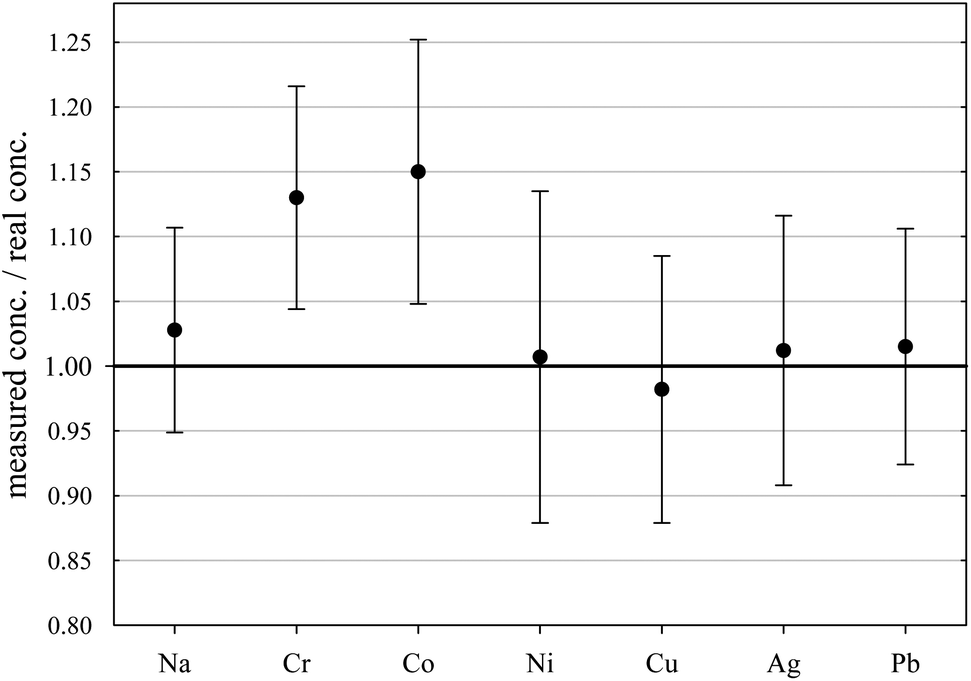 | ||
| Fig. 3 Analysis of a self-prepared frozen standard solution against NIST610 glass. The real concentration of all elements is 108 μg g−1. Error bars show 1RSD values of 11 analyses. | ||
Because of easier handling, for fluid inclusion analysis the NIST610 glass rather than frozen standard solutions was used for external calibration of element ratios in the fluids. The analyses were performed using the standard-bracketing method, with a standard ablation after every fourth sample. Final ice melting temperatures were determined by microthermometry and provided the NaCleq. values which were used as the internal standard for the calculation of elemental concentrations5 using the SILLS software.
2.3 Samples/synthetic fluid inclusions
To test our analytical setup we used synthetic fluid inclusions in quartz, which were generated from a standard solution of known concentration. The solution was prepared as a 1:1 mixture from the MERCK™ VIII ICPMS-multi-element-standard and a 20% NaCl solution; its composition is given in Table 3.
| Al | B | Ba | Be | Bi | Ca | Cd | Co | Cr | Cu | Fe | Ga |
| 52.3 | 52.8 | 52.8 | 53.3 | 53.3 | 52.8 | 52.8 | 52.8 | 52.3 | 53.3 | 52.8 | 53.9 |
| K | Li | Mg | Mn | Na* | Ni | Pb | Se | Sr | Te | Tl | Zn |
| 52.8 | 52.8 | 54.4 | 52.8 | 9.7* | 52.8 | 52.8 | 53.9 | 53.3 | 53.9 | 52.8 | 53.3 |
Preparation for fluid inclusion synthesis generally followed the workflow described by Bodnar et al.20 with minor modifications. Cores of 2.5 mm diameter and ca. 2 mm length were drilled from inclusion free alpine quartz, heated to 350 °C and subsequently immersed in concentrated hydrofluoric acid for 10 minutes to widen the cracks.
Two experiments were performed, one in a gold (ID188-Au) and one in a platinum (ID189-Pt) capsule, respectively, with dimensions of 20 mm length, 3.2 mm outer diameter and a wall thickness of 0.2 mm. In each capsule one pre-fractured quartz cylinder was placed together with 5 μg silica gel (to accelerate crack healing) and 30 μl of the standard solution. The capsules were pressurized to 200 MPa and heated isobarically in a rapid-heat/rapid-quench hydrothermal autoclave of a design described by Matthews et al.,21 using argon as pressure medium. Uncertainties of temperature and pressure measurements are considered to be ±5 °C and ±5 MPa, respectively. After a runtime of 5 days the autoclave was slowly cooled to room temperature. The recovered capsules were weighed to check for potential leaks during the run. The quartz cylinders were cleaned, dried and embedded in Araldite to be cut and polished to chips of 300 μm thickness.
From both experiments the quartz chips contained abundant synthetic fluid inclusions and 55 inclusions were selected for microthermometric and LA-ICP-MS analyses. Microthermometric measurements of ice melting temperatures Tm(ice) of −6.2 ± 0.1 °C correspond to a salinity of 9.47 ± 0.13 mass% NaCleq., calculated after Bodnar,22 which is in full agreement with the standard solution composition.
2.4 Ablation procedure
In this study we followed the workflow for fluid inclusion analysis reported by Heinrich et al.3 Since the inclusions are analyzed in a frozen state, problems such as explosive opening and sputtering of the inclusion content during ablation could be excluded, and we were able to use the so-called ‘straight ablation’ for the measurements. In contrast to the stepwise opening procedure which is used especially for polyphase inclusions, the “straight ablation” procedure holds some advantages, as reported by Pettke et al.2 These are (1) a lower amount of surface contamination, (2) higher signal/background ratios and (3) lower limits of detection (LOD).Prior to ablation the samples and reference materials were cleaned with deionized water and acetone, and the heating–freezing cell was wiped out carefully with dilute nitric acid. The positions of the inclusions were mapped off-line prior to the analyses using a standard petrographic microscope, which simplifies the search with the video system of the LA stage.
In the first step the fluid inclusions are frozen quickly by lowering the sample temperature to −100 °C. Depending on the fluid inclusion chemistry, the temperature is subsequently raised to a temperature sufficiently below the solution's eutectic point, so that the inclusions remain entirely frozen. Reference materials were analyzed at the same temperatures since the tuning of the mass spectrometer is also performed under these conditions. For the synthetic fluid inclusions the heating–freezing cell was set to −40 °C, since they were generated from a simple binary NaCl–H2O fluid.
A gas blank of at least 40 seconds was recorded prior to each single analysis before the start of ablation. The scan speed for the raster pattern performed on the used SRM was set to 20 μm s−1.
2.5 Data processing
For calculation of trace element concentrations in fluid inclusions it is necessary to separate the inclusion signal from the chemically distinct signal of the host mineral. We used the data reduction software SILLS,23 which is able to separate the short transient signal of the inclusion by a matrix correction. The software follows the procedures and equations from Allan et al.,8 Halter et al.,7 Heinrich et al.3 and Longerich et al.24 As silicon in the inclusion is negligible compared to silicon in the quartz, it was used as the matrix-only tracer. Three integration windows for background, matrix and inclusion signal were defined for each single analysis. The length of the integrated inclusion signal was adjusted to that of Na, because Na was used as the internal standard for the quantification of the elemental concentrations. Sample compositions were calculated using the mass balance approach of SILLS.As reported by Pettke et al.,2 the best way to determine concentration values and analytical uncertainties for LA-ICP-MS analyses of fluid inclusions is to calculate the mean value and the external error from a batch of analysis of individual inclusions belonging to the same assemblage. The analytical error is based on the external precision (1SD) and is defined as the relative standard deviation (RSD) in %. Since all inclusions in our samples are considered to be chemically identical, we calculated the average concentration and the RSD from all single analyses of one sample.
3. Results and discussion
3.1 Accuracy and precision
We used synthetic inclusions to check the analytical precision and accuracy of our method. By dividing the measured concentration with the theoretical value of the starting solution used for the high pressure/high temperature (HP/HT) experiment, the relative accuracy of these measurements can be estimated. The experimental solution contains 24 elements from the MERCK™ VIII ICPMS-standard-solution with known concentrations (Table 3). However, only 10 of them could be recovered in the synthesized fluid inclusions.The missing elements probably either reacted with the capsule material (e.g. the transition metals with Au or Pt) or have been enriched at the surface of the quartz host phase due to diffusive processes, like Li, Mg, Al and K. Consequently the original concentration of ∼53 μg g−1 in the experimentally synthesized fluid inclusions was found for only a few elements (Fig. 4). The two samples ID188-Au and ID189-Pt were analyzed in separate sessions. In total 53 of 55 measured inclusions could be analyzed successfully. Only two inclusions that were located directly under the sample surface could not be used for quantification, as a matrix correction could not be performed due to the missing separation of the host mineral signal from the inclusion signal. Single values, which lie beyond the 2SD threshold, were considered as outliers and have not been used for the calculation of mean values and standard deviations (Tables 4 and 5). Note that 195Au and 197Pt are not contained in the MERCK™ VIII standard solution and were likely leached out from the capsule material. The results for 11B, 111Cd, 125Te, 203Tl, 208Pb, and 209Bi (Fig. 4, Tables 4 and 5) indicate that these elements have been nearly completely recovered in the synthetic fluid inclusions and were measured with an accuracy relative to the starting composition of the fluid of >90%. The calculated mean value for these elements is in accordance with the original fluid compositions and is within analytical uncertainties (1RSD) i.e. between 13% (203Tl) and 25% (125Te) for sample ID188-Au and 17% (111Cd) to 25% (11B) for sample ID189-Pt (Fig. 5). 39K was only measured for sample ID189-Pt and could also be detected in the host mineral (quartz). After matrix correction, the determined K concentration of 42 μg g−1 (RSD = 37%) is in accordance with the original fluid. 64Zn was only analysed in some inclusions of sample ID189-Pt, with an average value of 37 μg g−1 (25% RSD). The concentrations determined for 9Be, 59Co, 69Ga, 88Sr and 137Ba in the synthesized fluid inclusions of both samples are significantly below the concentration of the original standard solution. Furthermore, the reproducibility of these elements was lower than that of the other elements in most cases. Beryllium, Co, and Ba show the highest variability with RSDs between 40% and 60%. Gold and Pt have also been analysed, because they were expected to be leached out of the capsule walls during the experiments. The inclusions in sample ID188-Au which were synthesized in gold capsules contain 1.6 wt% Au (RSD = 29%), which seems to be an extraordinary high value compared to Au concentrations in natural fluid inclusions that do not exceed the lower μg g−1 range.25,26 The mixture between the MERCK™ VIII solution, which is 1 M HNO3, and the NaCl-fluid may support the leaching of the capsule material during the experiments by formation of nitro-hydrochloric acid. Likewise, the inclusions in sample ID189-Pt which were synthesized in platinum capsules contain higher concentrations of Pt (124 μg g−1) which is heterogeneously distributed (with 73% RSD) and 11 μg g−1 Au (RSD = 26%). The inclusions can be separated into two groups with ∼200 μg g−1 and ∼50 μg g−1 Pt, respectively. Both groups have relatively homogeneous Pt concentrations with an RSD of 38% respective 34%. This may indicate formation of two generations of fluid inclusions in experiment ID189-Pt, which can only be identified due to their Pt concentration since all other elements show similar values in both groups. None of the other analyzed elements, except Pt and Au, could be identified to originate from the capsule material.
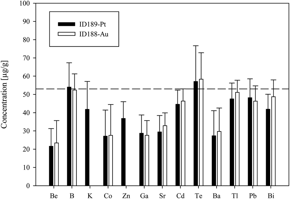 | ||
| Fig. 4 Results of the analysis of synthetic fluid inclusions from experiment ID188-Au (white columns) and ID189-Pt (black columns). The dashed line represents the starting composition of the experimental fluid, which was identical for both experiments. Only B, K, Cd, Te, Tl, Pb and Bi (for ID188-Au) could be fully recovered in the inclusions. Error bars show 1SD of the mean values from all analyzed inclusions from the specific sample. | ||
| Name | 9Be | 11B | 23Na | 39K | 59Co | 64Zn | 69Ga | 88Sr | 111Cd | 125Te | 137Ba | 195Pt | 197Au | 203Tl | 208Pb | 209Bi |
|---|---|---|---|---|---|---|---|---|---|---|---|---|---|---|---|---|
| μg g−1 | μg g−1 | μg g−1 | μg g−1 | μg g−1 | μg g−1 | μg g−1 | μg g−1 | μg g−1 | μg g−1 | μg g−1 | μg g−1 | μg g−1 | μg g−1 | μg g−1 | μg g−1 | |
| 18nov03 | 45 | 34 | 38054 |
— | 44 | — | 34 | 33 | 44 | 84 | 39 | — | 19873 |
45 | 45 | 49 |
| 18nov04 | 51 | 63 | 38054 |
— | 46 | — | 51 | 43 | 82 | 56 | 48 | — | 24320 |
51 | 57 | 53 |
| 18nov05 | 45 | 33 | 38054 |
— | 19 | — | 29 | 36 | 37 | 46 | 43 | — | 20044 |
42 | 43 | 34 |
| 18nov06 | 20 | 62 | 38054 |
— | 19 | — | 39 | 36 | 43 | 60 | 34 | — | 20618 |
53 | 53 | 53 |
| 18nov08 | 19 | 54 | 38054 |
— | 15 | — | 23 | 30 | 46 | 26 | 21 | — | 19967 |
51 | 31 | 32 |
| 18nov09 | 16 | 41 | 38054 |
— | 43 | — | 25 | 33 | 42 | 53 | 32 | — | 13261 |
44 | 55 | 44 |
| 18nov10 | 8 | 55 | 38054 |
— | 17 | — | 28 | 30 | 46 | 52 | 22 | — | 13812 |
46 | 47 | 49 |
| 18nov11 | 25 | 58 | 38054 |
— | 32 | — | 34 | 38 | 47 | 70 | 30 | — | 20580 |
54 | 56 | 56 |
| 18nov13 | 28 | 53 | 38054 |
— | 47 | — | 36 | 43 | 44 | 49 | 43 | — | 17481 |
55 | 56 | 57 |
| 18nov14 | 25 | 57 | 38054 |
— | 54 | — | 33 | 42 | 45 | 81 | 41 | — | 17450 |
59 | 48 | 57 |
| 18nov15 | 19 | 47 | 38054 |
— | 16 | — | 30 | 36 | 52 | 65 | 23 | — | 18352 |
55 | 51 | 59 |
| 18nov16 | 27 | 65 | 38054 |
— | 37 | — | 27 | 41 | 58 | 62 | 39 | — | 17613 |
58 | 41 | 48 |
| 18nov20 | 51 | 63 | 38054 |
— | 53 | — | 43 | 43 | 53 | 58 | 47 | — | 3789 | 38 | 52 | 47 |
| 18nov21 | 24 | 53 | 38054 |
— | 20 | — | 28 | 25 | 45 | 73 | 28 | — | 19165 |
60 | 48 | 56 |
| 18nov23 | 9 | 51 | 38054 |
— | 5 | — | 15 | 24 | 50 | 57 | 13 | — | 10121 |
50 | 38 | 44 |
| 18nov24 | 6 | 63 | 38054 |
— | 13 | — | 26 | 29 | 45 | 109 | 10 | — | 18619 |
71 | 59 | 68 |
| 18nov25 | 26 | 53 | 38054 |
— | 38 | — | 34 | 37 | 46 | 85 | 30 | — | 22838 |
53 | 54 | 61 |
| 18nov26 | 30 | 56 | 38054 |
— | 56 | — | 25 | 53 | 45 | 71 | 53 | — | 14229 |
51 | 56 | 57 |
| 18nov28 | 20 | 47 | 38054 |
— | 36 | — | 20 | 40 | 37 | 52 | 43 | — | 9976 | 50 | 43 | 44 |
| 18nov29 | 14 | 47 | 38054 |
— | 5 | — | 17 | 28 | 38 | 44 | 18 | — | 13282 |
46 | 34 | 39 |
| 18nov30 | 4 | 53 | 38054 |
— | 2 | — | 17 | 22 | 48 | 57 | 10 | — | 13886 |
54 | 38 | 48 |
| 18nov31 | 36 | 30 | 38054 |
— | 39 | — | 16 | 26 | 26 | 7 | 31 | — | 5794 | 33 | 33 | 33 |
| 18nov33 | 36 | 58 | 38054 |
— | 24 | — | 41 | 34 | 68 | 60 | 29 | — |
27![[thin space (1/6-em)]](https://www.rsc.org/images/entities/i_char_2009.gif) 636 636
|
65 | 52 | 69 |
| 18nov34 | 11 | 53 | 38054 |
— | 1 | — | 19 | 23 | 49 | 53 | 9 | — | 13963 |
53 | 37 | 49 |
| 18nov35 | 18 | 54 | 38054 |
— | 13 | — | 19 | 25 | 44 | 52 | 17 | — | 11946 |
53 | 42 | 47 |
| 18nov36 | 23 | 37 | 38054 |
— | 24 | — | 31 | 23 | 41 | 33 | 19 | — | 8481 | 38 | 37 | 34 |
| 18nov19 | 168 | 152 |
38054
|
— | 40 | — | 3 | 6 | <2.1 | 26 | <1.1 | — |
11535
|
64 | <0.3 | 28 |
| Mean | 23 | 52 | — | — | 28 | — | 28 | 33 | 46 | 58 | 30 | — | 16070 |
51 | 46 | 49 |
| SD | 12 | 9 | — | — | 17 | — | 8 | 7 | 7 | 14 | 13 | — | 4727 | 7 | 8 | 9 |
| RSD | 52% | 17% | — | — | 61% | — | 29% | 21% | 14% | 25% | 43% | — | 29% | 13% | 18% | 19% |
| Accuracy* | 44% | 99% | — | — | 52% | — | 51% | 62% | 88% | 108% | 56% | — | — | 97% | 88% | 91% |
| n | 25 | 25 | 27 | — | 26 | — | 25 | 25 | 24 | 24 | 26 | — | 24 | 24 | 26 | 25 |
| Name | 9Be | 11B | 23Na | 39K | 59Co | 64Zn | 69Ga | 88Sr | 111Cd | 125Te | 137Ba | 195Pt | 197Au | 203Tl | 208Pb | 209Bi |
|---|---|---|---|---|---|---|---|---|---|---|---|---|---|---|---|---|
| μg g−1 | μg g−1 | μg g−1 | μg g−1 | μg g−1 | μg g−1 | μg g−1 | μg g−1 | μg g−1 | μg g−1 | μg g−1 | μg g−1 | μg g−1 | μg g−1 | μg g−1 | μg g−1 | |
| 19nov03 | 16 | 64 | 38054 |
44 | 80 | 45 | 33 | 30 | 38 | 74 | 44 | 141 | 17 | 60 | 49 | 34 |
| 19nov04 | 36 | 54 | 38054 |
20 | 3 | 19 | 56 | 11 | 43 | <6.7 | 8 | 49 | 16 | 35 | 18 | 55 |
| 19nov05 | 79 | 122 | 38054 |
146 | 19 | <4.3 | 29 | 29 | 47 | 107 | 37 | 196 | 8 | 39 | 40 | 49 |
| 19nov06 | 18 | 64 | 38054 |
59 | 42 | 48 | 22 | 39 | 46 | 96 | 37 | 215 | 14 | 61 | 55 | 43 |
| 19nov08 | <3.3 | 119 | 38054 |
110 | 21 | 31 | 12 | 30 | 22 | 42 | 24 | 100 | 10 | 64 | 30 | 33 |
| 19nov09 | 17 | 74 | 38054 |
<6.4 | 35 | 74 | 15 | 26 | 52 | 88 | 11 | 146 | 15 | 64 | 58 | 27 |
| 19nov10 | 32 | 57 | 38054 |
44 | 37 | 39 | 33 | 54 | 43 | 79 | 36 | 69 | 15 | 58 | 58 | 31 |
| 19nov11 | 16 | 30 | 38054 |
55 | 20 | 44 | 18 | 22 | 43 | 53 | 22 | 43 | 11 | 38 | 39 | 39 |
| 19nov14 | 24 | 74 | 38054 |
57 | 27 | 30 | 36 | 35 | 58 | 48 | 17 | 63 | 11 | 55 | 60 | 47 |
| 19nov15 | 33 | 56 | 38054 |
38 | 46 | 45 | 38 | 27 | 33 | 71 | 33 | 70 | 12 | 41 | 46 | 51 |
| 19nov16 | 16 | 45 | 38054 |
47 | 16 | 32 | 18 | 27 | 34 | 35 | 25 | 28 | 7 | 45 | 44 | 39 |
| 19nov17 | 23 | 59 | 38054 |
58 | 15 | 44 | 31 | 31 | 38 | 58 | 14 | 45 | 12 | 47 | 48 | 27 |
| 19nov19 | 15 | 53 | 38054 |
44 | 7 | 50 | 37 | 20 | 48 | 54 | 6 | 48 | 14 | 49 | 53 | 28 |
| 19nov20 | 7 | 61 | 38054 |
51 | 7 | 21 | 24 | 15 | 49 | 44 | 8 | 23 | 7 | 44 | 36 | 52 |
| 19nov21 | 12 | 48 | 38054 |
13 | 7 | 40 | 19 | 18 | 36 | 44 | 8 | 27 | 8 | 45 | 52 | 50 |
| 19nov22 | 35 | 57 | 38054 |
76 | 40 | 44 | 35 | 42 | 47 | 76 | 45 | 62 | 12 | 49 | 65 | 39 |
| 19nov24 | 11 | 58 | 38054 |
44 | 39 | 29 | 20 | 40 | 43 | 30 | 50 | 499 | 11 | 53 | 50 | 44 |
| 19nov25 | 22 | 53 | 38054 |
25 | 44 | <11.8 | 27 | 35 | 45 | 59 | 44 | 222 | 7 | 45 | 46 | 45 |
| 19nov26 | 40 | 55 | 38054 |
48 | 47 | 35 | 41 | 46 | 41 | 49 | 62 | 271 | 11 | 44 | 57 | 51 |
| 19nov27 | 28 | 63 | 38054 |
36 | 46 | 47 | 52 | 43 | 56 | 75 | 49 | 205 | 12 | 48 | 65 | 52 |
| 19nov29 | 12 | 52 | 38054 |
22 | 20 | 41 | 20 | 25 | 59 | 56 | 23 | 100 | 13 | 52 | 53 | 43 |
| 19nov30 | 9 | 64 | 38054 |
20 | 23 | 26 | 18 | 23 | 54 | 77 | 20 | 191 | 11 | 49 | 54 | 43 |
| 19nov31 | 15 | 55 | 38054 |
38 | 21 | 25 | 37 | 27 | 28 | <14.1 | 36 | 370 | 8 | 34 | 25 | 36 |
| 19nov32 | 36 | 55 | 38054 |
47 | 15 | 33 | 45 | 24 | 44 | 54 | 18 | 62 | 11 | 41 | 43 | 44 |
| 19nov34 | 29 | 16 | 38054 |
49 | 35 | 32 | 30 | 33 | 41 | 26 | 30 | 136 | 9 | 39 | 40 | 39 |
| 19nov35 | 19 | 29 | 38054 |
26 | 44 | 46 | 28 | 39 | 48 | 26 | 38 | 227 | 8 | 37 | 37 | 48 |
| 19nov37 | <4.1 | 57 | 38054 |
35 | 19 | 47 | 8 | 28 | 49 | 46 | 12 | 253 | 10 | 54 | 53 | 47 |
| Mean | 22 | 54 | — | 42 | 27 | 37 | 29 | 29 | 45 | 57 | 27 | 124 | 11 | 48 | 48 | 42 |
| SD | 10 | 13 | — | 15 | 14 | 9 | 11 | 9 | 8 | 19 | 14 | 93 | 3 | 9 | 10 | 8 |
| RSD | 45% | 24% | — | 37% | 53% | 25% | 35% | 30% | 17% | 34% | 50% | 73% | 26% | 18% | 21% | 19% |
| Accuracy* | 41% | 103% | — | 79% | 51% | 70% | 52% | 55% | 85% | 105% | 51% | — | — | 90% | 92% | 79% |
| n | 24 | 25 | 27 | 24 | 26 | 24 | 26 | 26 | 26 | 24 | 26 | 26 | 27 | 27 | 26 | 27 |
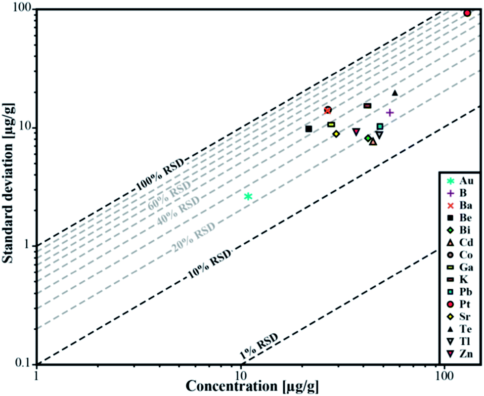 | ||
| Fig. 5 Relative standard deviation for the determined concentrations in sample ID189-Pt. Pt and Au were not part of the stock solution and were leached out of the capsule material. | ||
3.2 Limits of detection
The lower limits of detection vary for the measured isotopes over a range of three orders of magnitude (10−1 to 102 μg g−1). They were calculated using the method reported by Pettke et al.2 for integration windows, based on the total signal length of Na. The LODs are controlled by the laser repetition rate, the total integration time and the volume of the inclusions. Even though the differences in size of the analyzed inclusions are not large (8–26 μm), a significant correlation between LODs and inclusion size can still be observed (Fig. 6) which is the same for all analyzed elements. For lighter isotopes like 11B or 39K, the LODs vary between 4 μg g−1 and 16 μg g−1. Isotopes in the medium mass range like 59Co, 69Ga, or 88Sr have LODs between 0.3 μg g−1 and 1.8 μg g−1. Heavy isotopes like 195Pt and 209Bi show the lowest LODs (0.09–0.6 μg g−1). Furthermore, 195Pt and 197Au have been analyzed with a longer dwell time of 10 ms, resulting in a longer total integration time which improved the lower limit of detection.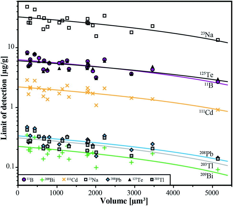 | ||
| Fig. 6 Limits of detection as a function of the inclusion volume for the 6 completely transferred elements (B, Cd, Te, Tl, Pb, Bi) and Na from all individual analyses from sample ID188-Au. | ||
4. Conclusions
We have tested a new analytical setup for the determination of trace element concentrations in fluid inclusion with fs-LA-ICP-MS. Ablation with femtosecond laser pulses allows analyzing fluid inclusions in their frozen state. With this technique, 53 of 55 synthetic fluid inclusions in quartz, covering a size range between 8 μm and 25 μm and down to a depth of 50 μm, could be analyzed successfully. The 194 nm UV-fs-laser allows excellent control over the opening procedure of fluid inclusions. Due to the low thermal heat transfer onto the sample surface the inclusions do not melt while the sample material is mobilized. It is even possible to measure very shallow inclusions that frequently explode, resulting in material loss during analysis under room temperature conditions with a nanosecond laser.The use of a fast scanning magnetic sector field ICP-MS with a SEM and a Faraday detector allows the detection of elements across the concentration range from μg g−1 to wt%. The lower limits of detection for fluid inclusion analysis vary between 0.1 μg g−1 (for 209Bi) and 10 μg g−1 (for 39K). The detection of 20 isotopes over the whole mass range takes 477 ms. The typical analytical uncertainty ranges between 15% and 30% (1RSD). This is a significant improvement in precision compared to earlier studies for samples with such low concentration levels. Elements from the stock solution which did not react with the capsule material or host mineral during the HP/HT experiments could be fully recovered in the synthetic fluid inclusions at their original concentrations. The results illustrate that our method is able to produce adequate data from natural fluid inclusions.
With respect to the time consuming work for preparation and characterization of fluid inclusion studies, especially microthermometry, our method offers a highly efficient tool for solute quantification in fluid inclusions with a success rate of >90%. First tests with natural inclusions in quartz have shown that the success rate can be expected to be similar to our results. Given that most natural samples often host only very few inclusions of sufficient size (≥10 μm), this method provides new possibilities for fluid inclusion studies. The applicability of our approach to the widespread UV-ns-LA systems needs to be tested. If successful, it may become a useful tool for the opening of fluid inclusions by LA-ICP-MS analysis.
Acknowledgements
We thank M. Wälle, C. A. Heinrich and D. Günther for their support and helpful discussion, F. Holtz and R. Botcharnikov for their experimental support, J. Feige, U. Kroll and B. Ecks for sample preparation and technical support, and New-Wave Research for providing the sample stage. This work was funded by the State of Lower Saxony (Germany), NTH Graduate School GeoFluxes.Notes and references
- A Practical Guide to Fluid Inclusion Studies, T. J. Shepherd, A. H. Rankin and D. H. M. Alderton, Blackie & Son Lmtd., Glasgow, 1985 Search PubMed.
- T. Pettke, F. Oberli, A. Audétat, M. Guillong, A. C. Simon, J. J. Hanley and L. M. Klemm, Ore Geol. Rev., 2012, 44, 10 CrossRef PubMed.
- C. A. Heinrich, T. Pettke, W. E. Halter, M. Aigner-Torres, A. Audétat, D. Günther, B. Hattendorf, D. Bleiner, M. Guillong and I. Horn, Geochim. Cosmochim. Acta, 2003, 67, 3473 CrossRef CAS.
- T. Pettke, F. Oberli, A. Audétat, U. Wiechert, C. R. Harris and C. A. Heinrich, J. Anal. At. Spectrom., 2011, 26, 475 RSC.
- D. Günther, A. Audétat, R. Frischknecht and C. A. Heinrich, J. Anal. At. Spectrom., 1998, 13, 263 RSC.
- D. Günther, B. Hattendorf and A. Audétat, J. Anal. At. Spectrom., 2001, 16, 1085 RSC.
- W. E. Halter, T. Pettke, C. A. Heinrich and B. Rothen-Rutishauser, Chem. Geol., 2002, 183, 63 CrossRef CAS.
- M. Allan, B. W. D. Yardley, L. J. Forbes, K. I. Shmulovich, D. A. Banks and T. J. Shepherd, Am. Mineral., 2005, 90, 1767 CrossRef CAS.
- M. Guillong, C. Latkoczy, J. H. Seo, D. Günther and C. A. Heinrich, J. Anal. At. Spectrom., 2008, 23, 1581 RSC.
- J. H. Seo, M. Guillong, M. Aerts, Z. Zajacz and C. A. Heinrich, Chem. Geol., 2011, 284, 35 CAS.
- I. Horn and F. von Blanckenburg, Geochim. Cosmochim. Acta, 2006, 70, 3677 CrossRef CAS PubMed.
- G. Steinhoefel, I. Horn and F. von Blanckenburg, Chem. Geol., 2009, 268, 67 CrossRef CAS PubMed.
- G. Steinhoefel, I. Horn and F. von Blanckenburg, Geochim. Cosmochim. Acta, 2009, 73, 5343 CrossRef CAS PubMed.
- G. Steinhoefel, F. von Blanckenburg, I. Horn, K. Konhauser, N. Beukes and J. Gutzmer, Geochim. Cosmochim. Acta, 2010, 74, 2677 CrossRef CAS PubMed.
- I. Horn and F. von Blanckenburg, Spectrochim. Acta, Part B, 2007, 62, 410 CrossRef PubMed.
- A. Borisova, R. Thomas, S. Salvi, F. Candaudap, A. Lanzanova and J. Chmeleff, Mineral. Mag., 2012, 76, 91 CrossRef CAS PubMed.
- P. Pronko, S. Dutta, D. Du and R. Singh, J. Appl. Phys., 1995, 78, 6233 CrossRef CAS PubMed.
- Y. Hirayama and M. Obara, J. Appl. Phys., 2005, 97, 064903 CrossRef PubMed.
- R. Hegenröder, J. Anal. At. Spectrom., 2006, 21, 505 RSC.
- R. Bodnar, C. Burnham and S. Sterner, Geochim. Cosmochim. Acta, 1985, 49, 1861 CrossRef CAS.
- W. Matthews, R. Linnen and Q. Guo, Am. Mineral., 2003, 88, 701 CAS.
- R. Bodnar, Geochim. Cosmochim. Acta, 1993, 57, 683 CrossRef CAS.
- M. Guillong, D. Meier, M. Allan, C. Heinrich and B. W. D. Yardley, Short Course Ser. - Mineral. Assoc. Can., 2008, 40, 328 CAS.
- H. Longerich, S. Jackson and D. Günther, J. Anal. At. Spectrom., 1996, 11, 899 RSC.
- T. Ulrich, D. Günther and C. A. Heinrich, Econ. Geol., 2001, 96, 1743 CrossRef CAS.
- C. A. Heinrich, D. Günther, A. Audétat, T. Ulrich and R. Frischknecht, Geology, 1999, 27, 755 CrossRef CAS.
| This journal is © The Royal Society of Chemistry 2014 |