
 Open Access Article
 This Open Access Article is licensed under a
 Creative Commons Attribution 3.0 Unported Licence
Influence of single- and double-flame spray pyrolysis on the structure of MnOx/γ-Al2O3 and FeOx/γ-Al2O3 catalysts and their behaviour in CO removal under lean exhaust gas conditions
Marina
Tepluchin
a,
David K.
Pham
b,
Maria
Casapu
a,
Lutz
Mädler
b,
Sven
Kureti
c and
Jan-Dierk
Grunwaldt
*a
aInstitute for Chemical Technology and Polymer Chemistry (ITCP), Karlsruhe Institute of Technology (KIT), Engesserstr. 20, D-76131 Karlsruhe, Germany. E-mail: grunwaldt@kit.edu; Fax: +49 7211 608 44805; Tel: +49 7211 608 42120
bDepartment of Production Engineering, Foundation Institute of Material Science (IWT), University of Bremen, Badgasteiner Str. 3, D-28359 Bremen, Germany
cInstitute of Energy Process Engineering and Chemical Engineering (IEC), Technical University of Freiberg, D-09596 Freiberg, Germany
First published on 2nd September 2014
Abstract
MnOx/Al2O3 and FeOx/Al2O3 samples were prepared by two-nozzle flame spray pyrolysis to minimize the formation of composite phases. For this purpose, manganese(II) naphthenate or iron(II) naphthenate and aluminium-sec-butylate were sprayed in separate flames and both the structure and the catalytic performance of the materials in CO oxidation were compared to the corresponding single-nozzle flame spray pyrolysis catalysts. Characterization by X-ray diffraction, diffuse reflectance UV-vis spectroscopy and X-ray absorption near-edge structure unravelled that the phases formed in double-flame spray pyrolysis (DFSP) were significantly different from those in single-flame spray pyrolysis; highly dispersed separate entities of manganese/iron oxide and alumina were identified in this case. Despite a slightly lower BET surface area the DFSP prepared samples performed generally better in catalytic CO oxidation than those derived from one single flame. In addition, the manganese-based catalysts were more effective for CO conversion than the corresponding iron-based samples, even at low concentrations.
Introduction
Diesel oxidation catalysis (DOC) is one of the major technologies in exhaust gas aftertreatment systems of lean burn engines to oxidize pollutants, such as CO, non-combusted hydrocarbons and the organic fraction of diesel particulates, to harmless exhaust gas products.1 For this purpose, usually Pt and Pd catalysts supported on different carriers are used.2,3 Non-noble metal catalysts such as copper-, nickel- and cobalt-based have also demonstrated significant catalytic activities, for example, in CO oxidation as test reaction.4,5 Unfortunately, they show lower thermal stability and are sensitive to poisoning.6,7 Poisoning by sulfur can be easier overcome in future because of ultra-low sulphur contents in gasoline or the use of sulphur-free synthetic fuels.In addition, unsupported and SBA-15-supported manganese oxide catalysts8,9 have been tested for this application.10,11 The following trend for CO oxidation activity was found: MnO ≤ MnO2 < Mn2O3.10 Furthermore, the MnOx-supported catalysts are also promising in NO and soot oxidation.12,13 In some cases a strong influence of the particle size on the catalytic activity has been found, but this effect is much less pronounced for metal oxide-based catalysts than for noble metal catalysts.14 In contrast to Mn oxides, only a few studies on Fe-based CO oxidation catalysts were reported.15,16 Recent DFT calculations showed that Fe2O3 nanoparticles particularly with (100) and (0001) surfaces are able to oxidize CO to CO2 efficiently.17 Moreover, iron oxide nanoparticles were found to exhibit high catalytic activity for CO, CH4, and C3H6 oxidation.18
Different synthesis methods have been used for the preparation of Mn- and Fe-based alumina catalysts such as co-precipitation and conventional incipient wetness impregnation.19–21 As a function of loading and calcination temperature, various Fe- and especially Mn-based oxide phases can be formed which exhibit different catalytic activities.8,22,23 In this context, the synthesis by flame spray pyrolysis (FSP) appears to be attractive since it allows the preparation in one step without any additional drying and calcination of the samples and it often leads to high surface area and crystallinity for 10–20 nm length scale nanomaterials.24–26 This method has already been applied to prepare a number of metal oxide-based particles such as SnO2, Fe2O3, ZrO2, ZnO and Al2O3.26,27 Furthermore, the method has received strong interest in the exhaust gas aftertreatment, e.g. for three-way or diesel oxidation catalysts.28–31 However, incorporation of the catalytically active phase into the alumina carrier or composite formation can be a problem for a standard single-nozzle flame spray pyrolysis system. For example, Strobel et al.32 found the formation of BaAl2O4 in NOx-storage-reduction catalysts when spraying barium, aluminium, and Pt precursor solutions together. Høj et al.33 observed the incorporation of Co into the alumina support of Co–Mo/Al2O3 catalysts applied for hydrodesulphurization. The group of Choi further reported on the formation of spinel-like ZnMn2O4 during FSP preparation.34 In line with these results, binary Fe- and Mn-based γ-alumina CO oxidation catalysts prepared by the FSP method also showed the incorporation of Fe and Mn species, especially for low Mn and Fe loadings (<1 wt.%).13 Several strategies to avoid the formation of incorporated species during FSP have been reported. Colloidal SiO2 particles were successfully sprayed for obtaining ZnO–SiO2 catalysts by Ramin et al.35 An alternative possibility is double-flame spray pyrolysis (DFSP), where the precursor solutions are sprayed in two different flames. This led to the successful formation of, for example, separate alumina and Pt/Ba particles without formation of BaAl2O4 when DFSP instead of single FSP is used.32 Using this technique, the formation of CoAl2O4 could also be prevented when using Co–Mo/Al2O3 catalysts, which usually leads to decrease in catalytic activity by hydrodesulphurization,36 and it was successfully applied for synthesis of alumina-supported cobalt Fischer–Tropsch catalysts.37
In the present study, we have systematically investigated the use of double-flame spray pyrolysis for the preparation of Mn/Al2O3 and Fe/Al2O3 catalysts in comparison to single-flame spray pyrolysis. The materials have been analysed by a number of characterization techniques (BET, XRD, UV-vis, XANES) to unravel whether eventual incorporation of Fe and Mn oxides could be prevented. CO oxidation served as a typical model reaction for environmental catalysts.
Experimental
Preparation of Mn/Al2O3 and Fe/Al2O3 by flame spray pyrolysis
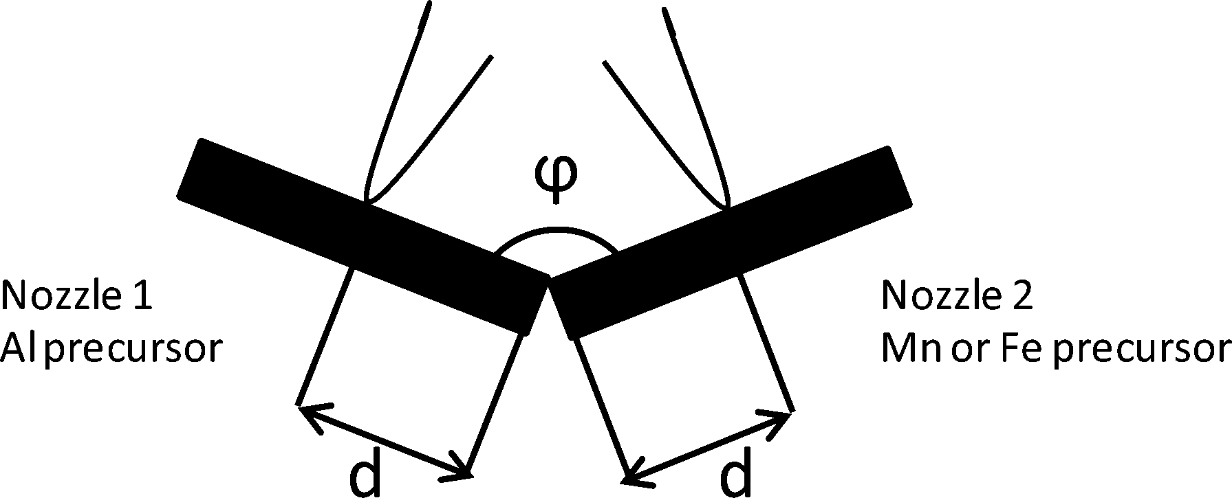 | ||
| Fig. 1 Sketch of two-nozzle FSP showing the angle between the two nozzles (φ) and the inter-nozzle distance between the angle tip and each nozzle center (d). | ||
For two-nozzle FSP, both precursor solutions were fed through capillary tubes at 5 ml min−1 using syringe pumps and were dispersed with 5 l min−1 high velocity gas flow of oxygen at a 1.5 bar pressure drop from a small annulus around the capillary open end. The spray was ignited with an annular premixed methane flame (3.2 l min−1 O2 and 1.5 l min−1 CH4). The gas flow was controlled by mass flow controllers. The product particles were collected 55 cm above the nozzle onto water-cooled glass-fiber filters (Whatman GF6, 257 mm) in a round filter holder connected to a vacuum pump (Busch SV 1025C). Single-nozzle FSP was performed by spraying the premixed precursor solution of Mn, Fe, and Al at the same setup in one of the flames.
Catalyst characterization
X-ray diffraction (XRD) patterns were obtained with a Bruker D8 Advance diffractometer using Cu Kα radiation with a Ni filter. XRD scans were recorded with steps of 0.016° in the 2θ range of 20 to 80°. The accelerating voltage and anode current were 40 kV and 35 mA, respectively. Data evaluation was performed using the data bank of the Joint Committee on Powder Diffraction Standards, and the two commercial oxides β-MnO2 (85%, Merck) and α-Fe2O3 (97%, Alfa Aesar) were used for comparison.X-ray absorption near-edge structure (XANES) experiments were conducted at the XAS beamline at the ANKA synchrotron light source (Karlsruhe, Germany) using a Si (111) double-crystal monochromator detuned to 60 wt.% of the maximum intensity for harmonic rejection. The storage ring was operated at 2.5 GeV and electron currents of 85–180 mA. Ex situ measurements were performed using pellets pressed with cellulose. For in situ studies (temperature-programmed reaction in 5 vol.% H2/He), a capillary microreactor heated with a hot air blower (Oxford) was used as described in detail elsewhere.39,40 Three ionization chambers were used for detecting the incoming and transmitted X-ray intensity of the sample and metallic Mn or Fe foils were measured for energy calibration. For fluorescence detection in the case of 0.2 wt.% samples, an energy-dispersive 5-element solid-state detector (Canberra LeG 5) was used. Normalization of the spectra, energy calibration and background removal were performed with the Athena program of the IFEFFIT package.41 For comparison, powdered standards of manganese (MnO2, Mn2O3, MnO) and iron (FeO, α-Fe2O3, γ-Fe2O3, and Fe3O4) with known oxidation state and geometry were investigated. Linear combination fitting analysis was performed on the normalized spectra in the −20 to +30 eV range around the absorption energy E0.
The specific surface areas (SSA) of the as-prepared oxide catalysts were measured by nitrogen adsorption/desorption applying a Belsorp mini II from Bel Japan using multipoint BET in the p/p0 = 0.05–0.3 range at liquid nitrogen temperature.42 The error is ±2 to 3 m2 g−1. Prior to measurements, the samples were degassed at 350 °C in vacuum for 2 h.
Diffuse Reflectance UV-vis spectroscopy data were obtained using a Perkin Elmer spectrometer (Lambda 650) with diffuse reflectance optics. The spectra were collected in the range of 190 to 800 nm with an instrumental resolution of 1 nm. The spectra were analysed using the Kubelka–Munk theory,43 where F(R∞) = (1 − R∞)2/2R∞. R∞ is the percentage reflection of an infinite layer of the sample relative to the carrier. The spectra were deconvoluted with Gaussian functions using Origin 8.6.
Catalytic tests
CO oxidation as a catalytic test reaction was conducted in a fixed-bed tubular quartz glass reactor of 8 mm inner diameter at atmospheric pressure in the temperature range of 100–350 °C. The feed consisted of 500 ppm CO, 5 vol.% O2 and N2 in balance, with a total flow of 500 ml min−1. 100 mg of the catalyst was diluted with 400 mg of Al2O3, loaded in the middle of the quartz glass reactor (as sieved granulate fraction of 125–250 μm) and fixed with two thermocouples in front and behind the catalyst bed to detect the temperature. Before each catalytic test the samples were heated for 30 min in 10 vol.% O2/N2 at 350 °C to remove adsorbed water from the surface. CO detection was performed with an online NDIR analyser (Hartmann & Braun, URAS, E10). The CO conversion was calculated based on the inlet and outlet concentrations of CO.Results and discussion
Characterization
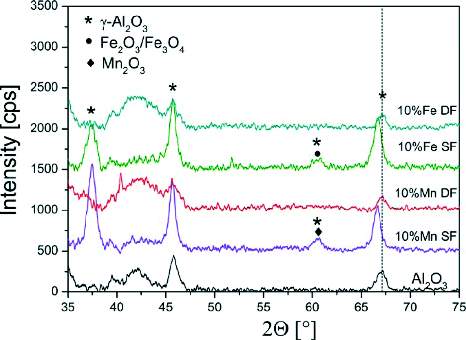 | ||
| Fig. 2 XRD diffraction patterns of the single- and double-nozzle FSP samples of 10 wt.% Mn- and Fe/Al2O3 showing mainly the reflections typical for γ-Al2O3 (compare also with ref. 13). | ||
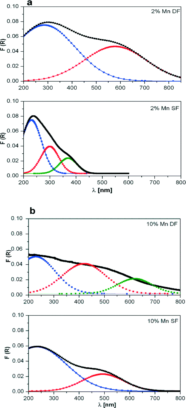 | ||
| Fig. 3 DR UV-vis spectra of a) 2 wt.% Mn/Al2O3 and b) 10 wt.% Mn/Al2O3 prepared by DF and SF. For each spectrum, R2 is about 0.98. | ||
The deconvolution results of the DR UV-vis spectra of 10 wt.% Mn/Al2O3 SF show two main absorption bands, one centred near 250 nm and one wide band at about 500 nm which covers almost all of the visible range of the spectrum (Fig. 3b bottom). For the 2 wt.% Mn/Al2O3 SF sample only a stronger absorption band at 250 nm with shoulders at 300 and 375 nm was obtained (Fig. 3a bottom). The observed spectra for supported manganese oxides can be interpreted on the basis of literature studies, e.g. the study by Stamatis et al.56 According to their results, the first absorption band is associated with an O2− to Mn2+ charge transfer transition with Mn located on the surface of alumina, whereas the latter is attributed to badly resolved absorbance bands (d–d transitions) originating from Mn(III) and Mn(IV) oxide species. Possibly, this is also connected to larger clusters of manganese oxides.
Two maxima have been observed for 2 wt.% Mn/Al2O3 DF, which shifted toward higher wavelengths in comparison to 2 wt.% Mn/Al2O3 SF (Fig. 3a top and bottom, respectively). The absorption spectrum of 10 wt.% Mn/Al2O3 DF covers almost the entire visible range up to 800 nm. Three absorption bands at ca. 250, 500 and 650 nm demonstrate the presence of small and larger clusters of Mn2+/Mn3+/Mn4+. Particularly, the band at 650 nm evidences the formation of separate metal oxides during the preparation procedure, although they are not visible by XRD.
In the same way, Fe-based catalysts were characterized using DR UV-vis spectroscopy (Fig. 4). A strong overlap of the bands is observed, and again for the elucidation of the different iron species (isolated, polymeric and crystalline iron oxide) up to three Gaussian curves were used for the deconvolution.54 The spectra, which are depicted in Fig. 4, show an increase in the total absorption area with Fe content in the case of DF-prepared samples, which is in agreement with the literature.54 The bands are probably due to charge transfer transitions (O2− → Fe3+).54,57 The absorption maximum in the region 200–300 nm indicates formation of isolated species (cf. assignment of UV-vis bands in ref. 55 and 58). Gaussian curves, which are located in the 300–400 nm range, are assigned to oligomers, and those appearing at higher wavelengths correspond to agglomerated particles, a classification presented earlier by Peréz-Ramírez et al.58 In the case of SF-prepared samples the more pronounced absorption maximum in the 200–300 nm region indicates formation of Fe oxide species incorporated into the alumina and corroborates the XRD results. The broader spectra with contributions at higher wavelengths observed from DF samples suggest the formation of oligomeric species or Fe oxides on the alumina surface. In conclusion, the results indicate that more separate iron and manganese oxide particles or clusters are formed in the case of two-nozzle flame spray pyrolysis which requires further elucidation by other characterization methods.
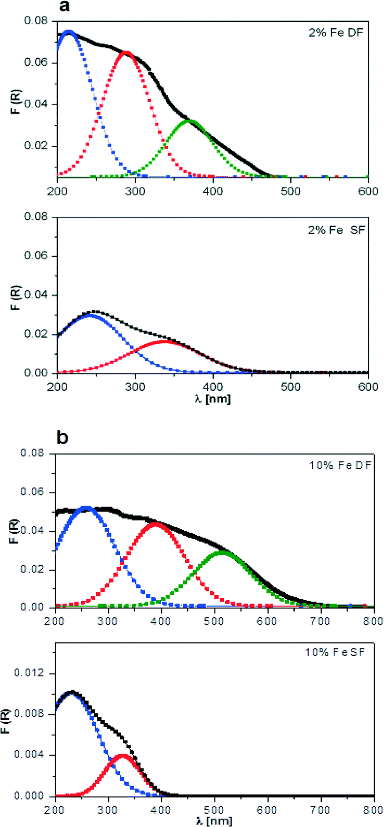 | ||
| Fig. 4 DR UV-vis spectra of a) 2 wt.% Fe/Al2O3 and b) 10 wt.% Fe/Al2O3 prepared by DF and SF. For each spectrum, R2 is about 0.98. | ||
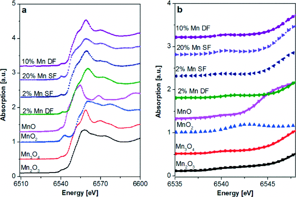 | ||
| Fig. 5 Mn K-edge XAS spectra of catalysts prepared by DF and SF methods and references, a) XANES region and b) zoom into the pre-edge of the Mn K-edge spectra. | ||
| Referencea | 2 wt.% Mn DF | 2 wt.% Mn SF | 10 wt.% Mn DF | 20 wt.% Mn SF | Referencea | 2 wt.% Fe DF | 2 wt.% Fe SF | 20 wt.% Fe DF | 20 wt.% Fe SF |
|---|---|---|---|---|---|---|---|---|---|
| a Reference: Mn and Fe oxides with different oxidation states/geometries used for LCA (cf. experimental section). | |||||||||
| MnO | 0.06 | 0.24 | 0.03 | 0.31 | FeO | 0.10 | 0 | 0 | 0 |
| Mn2O3 | 0.04 | 0 | 0 | 0.15 | α-Fe2O3 | 0.10 | 0 | 0.30 | 0 |
| γ-Fe2O3 | 0.28 | 0.67 | 0.23 | 0.32 | |||||
| Mn3O4 | 0.90 | 0.76 | 0.97 | 0.54 | Fe3O4 | 0.52 | 0.33 | 0.48 | 0.68 |
Moreover, during single-flame pyrolysis the possible formation of mixed Mn–Al oxides with decomposition during cooling in air to highly dispersed defect β-Mn3O4 oxide and amorphous Mn–Al–O should also be considered.50,56 The position of the pre-edge (Fig. 5b) for the 2 and 20 wt.% Mn/Al2O3 SF and 10 wt.% Mn/Al2O3 DF samples is similar to that of the Mn3O4 reference and is further supported by the linear combination analysis results (Table 3).
For both Fe catalysts prepared with double-flame spray pyrolysis an averaged oxidation state of +3 but with an almost equal Fe2O3 (α and γ)![[thin space (1/6-em)]](https://www.rsc.org/images/entities/char_2009.gif) :Fe3O4 phase distribution was obtained from the LCF analysis (Table 3). This is in agreement with DR UV-vis results. Only for the highly loaded 20 wt.% Fe SF sample the white line (especially the pre-edge region in Fig. 6b) is slightly more shifted toward lower energy, uncovering a different coordination environment. The similar structure of iron in γ-Fe2O3 and γ-Al2O3 together with the observation of isolated species in the case of SF samples in UV-vis supports the idea that the iron is incorporated into the alumina lattice in those cases as also concluded from XRD. In contrast, the 20 wt.% Fe DF sample shows a shift to higher energies evidencing more γ- or α-Fe2O. (see Fig. 6). This is corroborated by the fitting results in Table 3.
:Fe3O4 phase distribution was obtained from the LCF analysis (Table 3). This is in agreement with DR UV-vis results. Only for the highly loaded 20 wt.% Fe SF sample the white line (especially the pre-edge region in Fig. 6b) is slightly more shifted toward lower energy, uncovering a different coordination environment. The similar structure of iron in γ-Fe2O3 and γ-Al2O3 together with the observation of isolated species in the case of SF samples in UV-vis supports the idea that the iron is incorporated into the alumina lattice in those cases as also concluded from XRD. In contrast, the 20 wt.% Fe DF sample shows a shift to higher energies evidencing more γ- or α-Fe2O. (see Fig. 6). This is corroborated by the fitting results in Table 3.
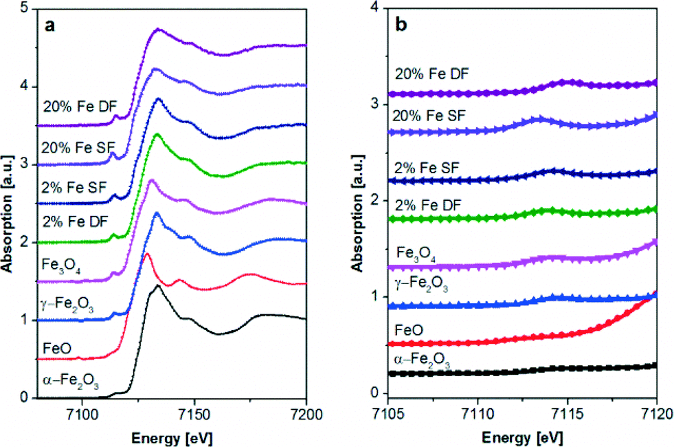 | ||
| Fig. 6 Fe K-edge XAS spectra of catalysts prepared by DF and SF methods and references. a) XANES region and b) zoom into the pre-edge of the Fe K edge spectra. | ||
To elucidate the impact of the preparation procedure on the reducibility of the Mn sites, quick EXAFS spectra were collected during temperature-programmed reduction (TPR) experiments in 5 vol.% H2/He. An earlier onset of the reduction temperature could be linked to an improved low temperature activity in the case of a Mars van Krevelen mechanism.68 The results of the linear combination fit analysis of the recorded spectra are shown in Fig. 7 and 8, respectively.
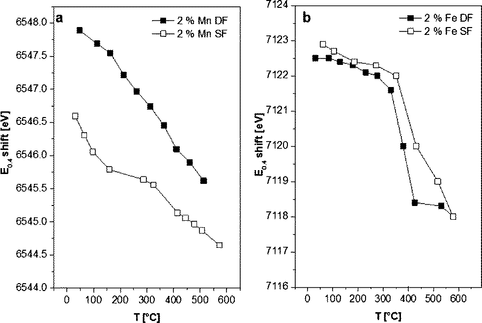 | ||
| Fig. 7 E 0.4 shift from samples prepared by DF and SF methods during in situ H2-TPR. a) 2 wt.% Mn/Al2O3 DF, 2 wt.% Mn/Al2O3 SF and b) 2 wt.% Fe/Al2O3 DF, 2 wt.% Fe/Al2O3 SF catalysts. | ||
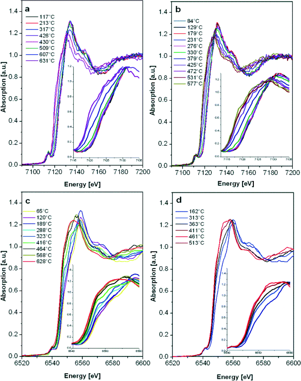 | ||
| Fig. 8 In situ H2-TPR XANES spectra at the Fe K-edge and the Mn K-edge of 2 wt.% a) Fe/Al2O3 SF, b) Fe/Al2O3 DF, c) Mn/Al2O3 SF and d) Mn/Al2O3 DF prepared catalysts. Insets: enlarged white-line region. | ||
Although the 2 wt.% Mn/Al2O3 DF sample contains more oxidized Mn sites, the reduction of both catalysts starts as soon as the temperature increases (>60 °C). A continuous reduction was recorded for the 2 wt.% Mn/Al2O3 DF so that at the end of the experiment a mixture of Mn2+/Mn3+ is present, while the SF catalyst is almost completely reduced to Mn2+. According to the literature, the reduction process follows the trend MnO2 → Mn2O3 → Mn3O4 → MnO,20,69 but the reduction in this case is continuous probably due to the strong interaction of Mn with the oxide surface. For bulk oxides the reduction would be more discrete.13
The E0.4 energy shift (the energy at 40% of the white line) recorded during the reduction of 2 wt.% Fe/Al2O3 DF- as well as for SF-prepared samples indicates the transition from γ-Fe2O3 to FeO,70 with no apparent intermediate step (e.g. Fe3O4 formation). Only a small increase in the reduction onset temperature was observed for the 2 wt.% Fe/Al2O3 SF catalyst. In addition, the reduction occurs over a broader temperature regime probably due to a higher dispersion of the Fe sites as shown by DR UV-vis measurements (Fig. 3) or the possible formation of alumina-incorporated species as also evidenced by other characterization methods.
Catalytic performance during CO oxidation
The results of the catalytic activity of SF- and DF-prepared Mn/Al2O3 samples are depicted in Fig. 9. The CO conversion increases simultaneously with the Mn content as well as temperature, i.e. at 300 °C the CO conversion reaches a maximum of 55% for the 10 wt.% Mn/Al2O3 DF sample. Regardless of the different structure evidenced by XRD, DR UV-vis and XAS, the observed data show only little differences in catalytic activity between the catalysts prepared by the two different methods. This is supported by the reducibility of the Mn sites observed between 50 and 300 °C for both 2 wt.% Mn/Al2O3 SF and DF catalysts. However, as can be seen for all loadings, the DF samples show slightly higher activity despite the higher surface area of the SF-prepared catalysts.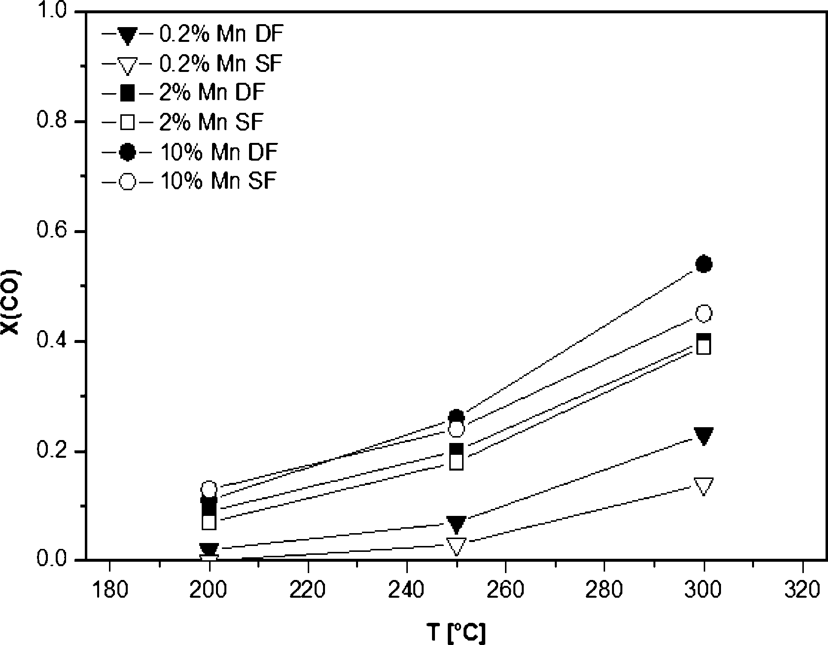 | ||
| Fig. 9 CO conversions of 0.2, 2 and 10 wt.% Mn/Al2O3 catalysts prepared by different methods. Conditions: 100 mg of the catalyst, 500 ppm CO, 5 vol% O2, balance N2, total flow 500 ml min−1, GHSV 30000 h−1. | ||
The catalytic results of DF-prepared Fe/Al2O3 samples are shown in Fig. 10 and demonstrate an increase in performance as a function of temperature and Fe loading up to 15 wt.%. For Fe loadings above 20 wt.% the catalytic activity decreases, which could be caused by the decrease in surface area (Table 1). Compared to the corresponding Mn-based catalyst, the catalytic activity of the 10 wt.% Fe/Al2O3 DF sample reaches a maximum of only 34% at 300 °C and of 10% at 200 °C. This is in line with the very limited reducibility of the Fe species as shown by in situ XAS-TPR measurements. Nevertheless, the 10 wt.% Fe/Al2O3 sample prepared by DFSP exhibited significantly higher CO oxidation activity than the corresponding SF catalyst (10% CO conversion at 300 °C), which is also the case for lower loaded samples (not shown). This tendency is in line with the already observed trend for the Mn-based catalyst series (Fig. 10).
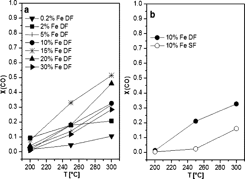 | ||
| Fig. 10 CO conversions as a function of temperature of a) 0.2, 2, 5, 10, 15, 20 and 30 wt.% Fe/Al2O3 prepared by DF and b) 10 wt.% Fe/Al2O3 samples prepared by DF and SF. Conditions: 100 mg catalyst, 500 ppm CO, 5 vol.% O2, balance N2, total flow 500 ml min−1, GHSV 30000 h−1. | ||
Fig. 11 provides an overview of the activity in terms of turnover frequency (TOF) related to the total number of manganese/iron oxide species and normalized with the surface area of the corresponding catalysts. A superior performance of the catalysts prepared by DFSP in comparison to the SF samples is especially found in the case of low loaded 0.2 wt.% samples. Hence, this strongly supports the idea that for the DF samples the incorporation of the catalytically active Mn and Fe-species into the alumina support is prevented.
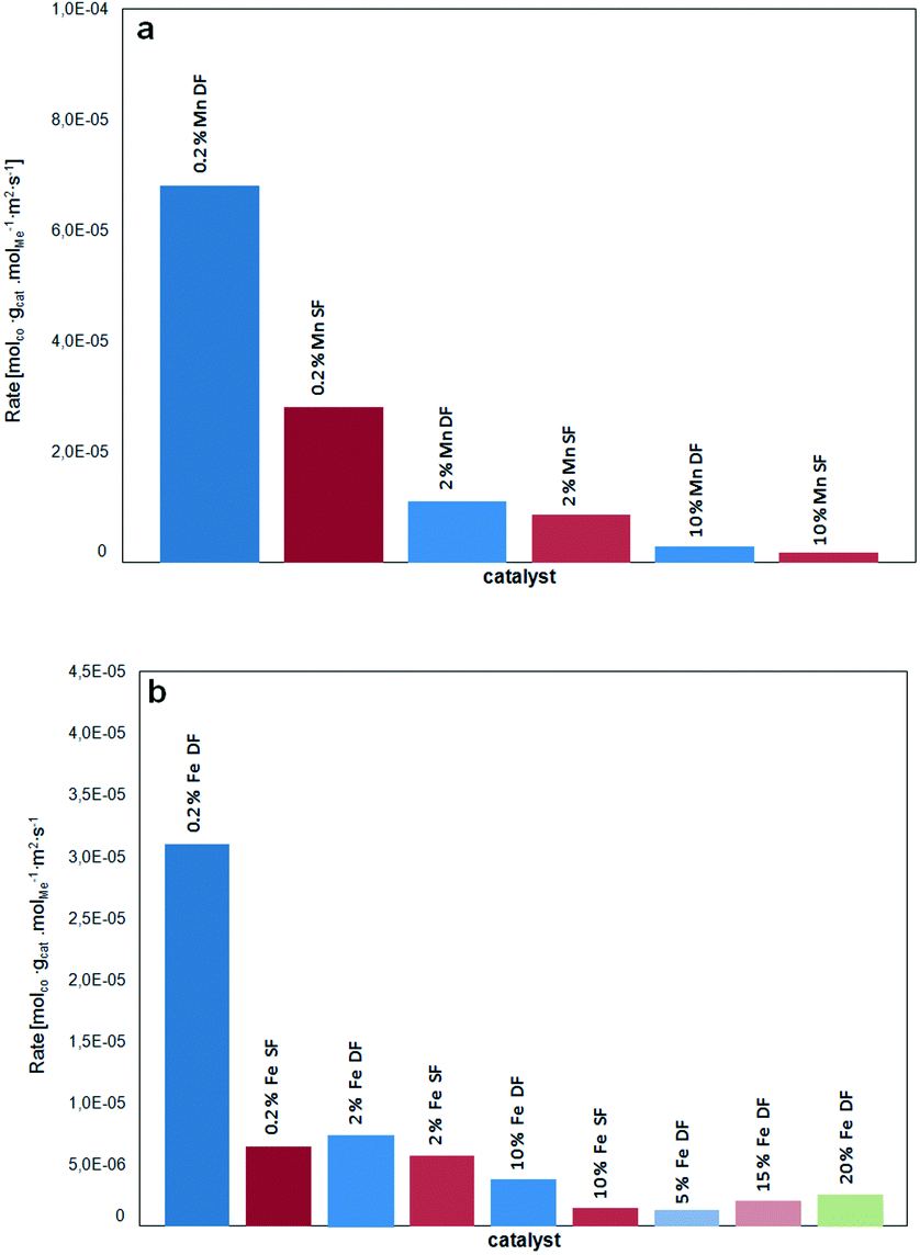 | ||
| Fig. 11 TOF of a) Mn/Al2O3 catalysts and b) Fe/Al2O3 catalysts in terms of molCO/(molmetal s) related to the BET surface area (m2 gcat−1) as a function of catalyst loading and preparation methods. | ||
However, in the case of Mn-based catalysts, the composite formation has a much lower influence on the catalytic performance. Apart from their intrinsic higher CO oxidation activity, this could be traced back to the observations of Bulavchenko et al.67 who demonstrated improved CO oxidation activity of the β-Mn3O4 phase formed from less active Mn aluminate by phase transformation in O2, a transformation that is not known for iron–aluminium mixed oxides.
Conclusions
Double-flame spray pyrolysis has been shown to be a suitable method to prevent the formation of incorporated manganese and particularly iron species into the Al2O3 lattice which are probably formed during single-flame spray pyrolysis synthesis. Despite a slightly lower surface area some improvements of the catalytic performance could be gained especially for low loaded Mn- and Fe-based samples. Also, the 10 wt.% Fe/Al2O3 sample prepared by DF showed a notable increase in the CO oxidation activity. In contrast, only minor differences for manganese-based catalysts with higher loadings (>10%) prepared by DF have been observed. In both cases (SF and DF), the manganese and iron oxides clusters were highly dispersed on the surface, exhibiting oxidation states between Mn(II)/Mn(III) and Fe(II)/Fe(III), respectively. Only the complementary use of several spectroscopic methods allowed tracing of the oxidic structures, and in future it would be of interest to tune the composite formation and to prove it by varying the angle between the two nozzles and the inter-nozzle distance between the angle tip and each nozzle centre. In addition, the stability of the flame-derived catalysts should be studied and compared to conventionally prepared catalysts to further conclude their potential for exhaust gas aftertreatment catalysis. In this respect, finding less costly, efficient and thermally stable non-noble metal catalysts not only for CO oxidation but also for the HC and diesel particulate matter oxidation and NOx reduction is of high interest, where flame spray methods show high potential.30Acknowledgements
The authors wish to thank ANKA (Karlsruhe, Germany) for providing beam time, Dr. Stefan Mangold for support during the XAS experiments at ANKA-XAS and Dr. Suman Pokhrel for catalyst preparation. We would also like to acknowledge the German Foundation of Environment (Deutsche Bundesstiftung Umwelt) for financing MT's PhD work and the BMBF within the project “Materials in Action” for the support of the setup of the in situ infrastructure at the synchrotron radiation source ANKA.References
- A. Russell and W. S. Epling, Catal. Rev.: Sci. Eng., 2011, 53, 337 CAS
.
- N. Lopez and J. K. Nørskov, J. Am. Chem. Soc., 2002, 124, 11262–11263 CrossRef CAS PubMed
- A. Manasilp and E. Gulari, Appl. Catal., B, 2002, 37, 17 CrossRef CAS
- X. Xie, Y. Li, Z.-Q. Liu, M. Haruta and W. Shen, Nature, 2009, 458, 746 CrossRef CAS PubMed
- S. Royer and D. Duprez, ChemCatChem, 2011, 3, 24–65 CrossRef CAS
- G. J. Barnes, Adv. Chem. Ser., 1975, 143, 72–84 CrossRef CAS PubMed
- Y. Yao, J. Catal., 1975, 36, 226 Search PubMed
- R. Craciun, B. Nentwick, K. Hadjiivanov and H. Knözinger, Appl. Catal., A, 2003, 243, 67–79 CrossRef CAS
- Y.-F. Han, F. Chen, Z. Zhong, K. Ramesh and L. C. E. Widjaja, J. Phys. Chem. B, 2006, 110, 24450–24456 CrossRef CAS PubMed
- K. Ramesh, L. Chen, F. Chen, Y. Liu, Z. Wang and Y.-F. Han, Catal. Today, 2008, 131, 477–482 CrossRef CAS PubMed
- K. Frey, V. Iablokov, G. Sáfrán, J. Osán, I. Sajó, R. Szukiewicz, S. Chenakin and N. Kruse, J. Catal., 2012, 287, 30–36 CrossRef CAS PubMed
- K. Tikhomirov, O. Kröcher, M. Elsener and A. Wokaun, Appl. Catal., B, 2006, 64, 72–78 CrossRef CAS PubMed
- M. Tepluchin, M. Casapu, A. Boubnov, H. Lichtenberg, D. Wang, S. Kureti and J.-D. Grunwaldt, ChemCatChem, 2014, 6, 1763–1773 CrossRef CAS
- V. Schwartz, D. R. Mullins, W. Yan, B. Chen, S. Dai and S. H. Overbury, J. Phys. Chem. B, 2004, 108, 15782–15790 CrossRef CAS
- S. Wagloehner, D. Reichert, D. Leon-Sorzano, P. Balle, B. Geiger and S. Kureti, J. Catal., 2008, 260, 305–314 CrossRef CAS PubMed
- H. Randall, R. Doepper and A. Renken, Ind. Eng. Chem. Res., 1997, 36, 2996–3001 CrossRef CAS
- A. K. Kandalam, B. Chatterjee, S. N. Khanna, B. K. Rao, P. Jena and B. V. Reddy, Surf. Sci., 2007, 601, 4873–4880 CrossRef CAS PubMed
- S. C. Kwon, M. Fan, T. D. Wheelock and B. Saha, Sep. Pur. Technol., 2007, 58, 40–48 CrossRef CAS PubMed
- B. R. Strohmeier and D. M. Hercules, J. Phys. Chem., 1984, 88, 4922–4929 CrossRef CAS
- J. Hu, W. Chu and L. Shi, J. Nat. Gas Chem., 2008, 17, 159–164 CrossRef CAS
- Q. Tang, X. Huang, C. Wu, P. Zhao, Y. Chen and Y. Yang, J. Mol. Catal. A: Chem., 2009, 306, 48–53 CrossRef CAS PubMed
- S. Cavallaro, N. Bertuccio, P. Antonucci, N. Giordano and J. C. J. Bart, J. Catal., 1982, 73, 337–348 CrossRef CAS
- W. S. Kijlstra, E. K. Poels, A. Bliek, B. M. Weckhuysen and R. A. Schoonheydt, J. Phys. Chem. B, 1997, 101, 309–316 CrossRef CAS
- H. K. Kammler, L. Mädler and S. E. Pratsinis, Chem. Eng. Technol., 2001, 24, 583 CrossRef CAS
- R. Strobel, A. Baiker and S. E. Pratsinis, Adv. Powder Technol., 2006, 17, 457–480 CrossRef CAS PubMed
- W. Y. Teoh, R. Amal and L. Mädler, Nanoscale, 2010, 2, 1324–1347 RSC
- R. Strobel, F. Krumeich, W. J. Stark, S. E. Pratsinis and A. Baiker, J. Catal., 2004, 222, 307 CrossRef CAS PubMed
- W. Y. Teoh, R. Amal, L. Mädler and S. E. Pratsinis, Catal. Today, 2007, 120, 203–213 CrossRef CAS PubMed
- R. Strobel, J.-D. Grunwaldt, A. Camenzind, S. Pratsinis and A. Baiker, Catal. Lett., 2005, 104, 9–16 CrossRef CAS
- B. Weidenhof, M. Reiser, K. Stöwe, W. F. Maier, M. Kim, J. Azurdia, E. Gulari, E. Seker, A. Barks and R. M. Laine, J. Am. Chem. Soc., 2009, 131, 9207–9219 CrossRef CAS PubMed
- W. J. Stark, J.-D. Grunwaldt, M. Maciejewski, S. E. Pratsinis and A. Baiker, Chem. Mater., 2005, 17, 3352–3358 CrossRef CAS
- R. Strobel, L. Mädler, M. Piacentini, M. Maciejewski, A. Baiker and S. E. Pratsinis, Chem. Mater., 2006, 18, 2532–2537 CrossRef CAS
- M. Høj, K. Linde, T. K. Hansen, M. Brorson, A. D. Jensen and J.-D. Grunwaldt, Appl. Catal., A, 2011, 397, 201–208 CrossRef PubMed
- S. H. Choi and Y. C. Kang, Int. J. Electrochem. Sci., 2013, 8, 6281–6290 CAS
- M. Ramin, N. van Vegten, J.-D. Grunwaldt and A. Baiker, J. Mol. Catal. A: Chem., 2006, 258, 165–171 CrossRef CAS PubMed
- M. Høj, D. Pham, M. Brorson, L. Mädler, A. Jensen and J.-D. Grunwaldt, Catal. Lett., 2013, 143, 386–394 CrossRef
- M. Minnermann, S. Pokhrel, K. Thiel, R. Henkel, J. Birkenstock, T. Laurus, A. Zargham, J.-I. Flege, V. Zielasek, E. Piskorska-Hommel, J. Falta, L. Mädler and M. Bäumer, J. Phys. Chem. C, 2010, 115, 1302–1310 Search PubMed
- M. Minnermann, H. K. Grossmann, S. Pokhrel, K. Thiel, H. Hagelin-Weaver, M. Bäumer and L. Mädler, Catal. Today, 2013, 214, 90–99 CrossRef CAS PubMed
- J.-D. Grunwaldt, M. Caravati, S. Hannemann and A. Baiker, Phys. Chem. Chem. Phys., 2004, 6, 3037–3047 RSC
- J.-D. Grunwaldt, N. van Vegten and A. Baiker, Chem. Commun., 2007, 4635–4637 RSC
- B. Ravel and M. Newville, J. Synchrotron Radiat., 2005, 12, 537–541 CrossRef CAS PubMed
- S. Brunauer, P. H. Emmett and E. Teller, J. Am. Chem. Soc., 1938, 60 Search PubMed
- L. Yang and B. Kruse, J. Opt. Soc. Am. A, 2004, 21, 1933–1941 CrossRef
- M. C. Heine, L. Mädler, R. Jossen and S. E. Pratsinis, Combust. Flame, 2006, 144, 809–820 CrossRef CAS PubMed
- A. J. Gröhn, S. E. Pratsinis and K. Wegner, Chem. Eng. J., 2012, 191, 491–502 CrossRef PubMed
-
L. Mädler, in KONA, 2004, vol. 22, pp. 107–120j Search PubMed
- R. Strobel, W. J. Stark, L. Mädler, S. E. Pratsinis and A. Baiker, J. Catal., 2003, 213, 296–304 CrossRef CAS
- R. M. Laine, J. C. Marchal, H. P. Sun and X. Q. Pan, Nat. Mater., 2006, 5, 710–712 CrossRef CAS PubMed
- T. Hinklin, B. Toury, C. Gervais, F. Babonneau, J. J. Gislason, R. W. Morton and R. M. Laine, Chem. Mater., 2003, 16, 21–30 CrossRef
-
R. Schlögl, Bulk Catalysts and Supports, Wiley-VCH, Weinheim, 1st edn, 1997, vol. 1 Search PubMed
- G. C. Bye and G. T. Simpkin, J. Am. Ceram. Soc., 1974, 57, 367–371 CrossRef CAS PubMed
- K. Okada, A. Hattori, T. Taniguchi, A. Nukui and R. N. Das, J. Am. Ceram. Soc., 2000, 83, 928–932 CrossRef CAS PubMed
- F. Maglia, S. Gennari and V. Buscaglia, J. Am. Ceram. Soc., 2008, 91, 283–290 CrossRef CAS PubMed
- P. Balle, B. Geiger and S. Kureti, Appl. Catal., B, 2009, 85, 109–119 CrossRef CAS PubMed
- M. Høj, M. J. Beier, J.-D. Grunwaldt and S. Dahl, Appl. Catal., B, 2009, 93, 166–176 CrossRef PubMed
- N. Stamatis, K. Goundani, J. Vakros, K. Bourikas and C. Kordulis, Appl. Catal., A, 2007, 325, 322–327 CrossRef CAS PubMed
- F. Fan, K. Sun, Z. Feng, H. Xia, B. Han, Y. Lian, P. Ying and C. Li, Chem. – Eur. J., 2009, 15, 3268–3276 CrossRef CAS PubMed
- J. Pérez-Ramírez, J. C. Groen, A. Brückner, M. S. Kumar, U. Bentrup, M. N. Debbagh and L. A. Villaescusa, J. Catal., 2005, 232, 318–334 CrossRef PubMed
- T. E. Westre, P. Kennepohl, J. G. DeWitt, B. Hedman, K. O. Hodgson and E. I. Solomon, J. Am. Chem. Soc., 1997, 119, 6297–6314 CrossRef CAS
- F. Farges, Phys. Rev. B: Condens. Matter Mater. Phys., 2005, 71, 155109 CrossRef
- P. Glatzel, A. Mirone, S. G. Eeckhout, M. Sikora and G. Giuli, Phys. Rev. B: Condens. Matter Mater. Phys., 2008, 77, 115133–115137 CrossRef
- E. Chalmin, F. Farges and G. E. Brown, Contrib. Mineral. Petrol., 2009, 157, 111–126 CrossRef CAS
- F. Farges, Phys. Rev. B: Condens. Matter Mater. Phys., 2005, 71, 155109 CrossRef
- E. López-Navarrete, A. Caballero, A. R. González-Elipe and M. Ocaña, J. Eur. Ceram. Soc., 2004, 24, 3057–3062 CrossRef PubMed
- M. Ferrandon, J. Carnö, S. Järås and E. Björnbom, Appl. Catal., A, 1999, 180, 141–151 CrossRef CAS
- M. Ferrandon, J. Carnö, S. Järås and E. Björnbom, Appl. Catal., A, 1999, 180, 153–161 CrossRef CAS
- O. A. Bulavchenko, T. N. Afonasenko, P. G. Tsyrul'nikov and S. V. Tsybulya, Appl. Catal., A, 2013, 459, 73–80 CrossRef CAS PubMed
- K. Ramesh, L. Chen, F. Chen, Y. Liu, Z. Wang and Y.-F. Han, Catal. Today, 2008, 131, 477–482 CrossRef CAS PubMed
- F. Kapteijn, A. D. Vanlangeveld, J. A. Moulijn, A. Andreini, M. A. Vuurman, A. M. Turek, J. M. Jehng and I. E. Wachs, J. Catal., 1994, 150, 94–104 CrossRef CAS
- N. Shah, S. Pattanaik, F. E. Huggins, D. Panjala and G. P. Huffman, Fuel Process. Technol., 2003, 83, 163–173 CrossRef CAS
| This journal is © The Royal Society of Chemistry 2015 |