 Open Access Article
Creative Commons Attribution 3.0 Unported Licence
Quantum chemistry of the Fischer–Tropsch reaction catalysed by a stepped ruthenium surface†
I. A. W.
Filot
,
R. A.
van Santen
and
E. J. M.
Hensen
*
Laboratory of Inorganic Materials Chemistry, Schuit Institute of Catalysis, Technische Universiteit Eindhoven, P.O. Box 513, 5600 MB Eindhoven, The Netherlands. E-mail: e.j.m.hensen@tue.nl
First published on 19th June 2014
Abstract
A comprehensive density functional theory study of the Fischer–Tropsch mechanism on the corrugated Ru(11![[2 with combining macron]](https://www.rsc.org/images/entities/char_0032_0304.gif) 1) surface has been carried out. Elementary reaction steps relevant to the carbide mechanism and the CO insertion mechanism are considered. Activation barriers and reaction energies were determined for CO dissociation, C hydrogenation, CHx + CHy and CHx + CO coupling, CHxCHy–O bond scission and hydrogenation reactions, which lead to formation of methane and higher hydrocarbons. Water formation that removes O from the surface was studied as well. The overall barrier for chain growth in the carbide mechanism (preferred path CH + CH coupling) is lower than that for chain growth in the CO insertion mechanism (preferred path C + CO coupling). Kinetic analysis predicts that the chain-growth probability for the carbide mechanism is close to unity, whereas within the CO insertion mechanism methane will be the main hydrocarbon product. The main chain propagating surface intermediate is CH via CH + CH and CH + CR coupling (R = alkyl). A more detailed electronic analysis shows that CH + CH coupling is more difficult than coupling reactions of the type CH + CR because of the σ-donating effect of the alkyl substituent. These chain growth reaction steps are more facile on step-edge sites than on terrace sites. The carbide mechanism explains the formation of long hydrocarbon chains for stepped Ru surfaces in the Fischer–Tropsch reaction.
1) surface has been carried out. Elementary reaction steps relevant to the carbide mechanism and the CO insertion mechanism are considered. Activation barriers and reaction energies were determined for CO dissociation, C hydrogenation, CHx + CHy and CHx + CO coupling, CHxCHy–O bond scission and hydrogenation reactions, which lead to formation of methane and higher hydrocarbons. Water formation that removes O from the surface was studied as well. The overall barrier for chain growth in the carbide mechanism (preferred path CH + CH coupling) is lower than that for chain growth in the CO insertion mechanism (preferred path C + CO coupling). Kinetic analysis predicts that the chain-growth probability for the carbide mechanism is close to unity, whereas within the CO insertion mechanism methane will be the main hydrocarbon product. The main chain propagating surface intermediate is CH via CH + CH and CH + CR coupling (R = alkyl). A more detailed electronic analysis shows that CH + CH coupling is more difficult than coupling reactions of the type CH + CR because of the σ-donating effect of the alkyl substituent. These chain growth reaction steps are more facile on step-edge sites than on terrace sites. The carbide mechanism explains the formation of long hydrocarbon chains for stepped Ru surfaces in the Fischer–Tropsch reaction.
Introduction
The limited supply of readily available petroleum stimulates the search for alternative energy sources.1 Due to its abundance, natural gas is increasingly considered as a valuable alternative feedstock for the synthesis of fuels and chemicals. Synthesis gas (a mixture of CO and H2), which can be obtained from natural gas by autothermal or steam reforming, can be used to produce long-chain hydrocarbons in the Fischer–Tropsch (FT) reaction.2–4 Several mechanistic proposals for this chain-growth reaction have been reviewed elsewhere.5 They can be distinguished by the assumption of the inserting species in the growing chain. The inserting species is either a CHx monomer derived from surface CO dissociation in the carbide mechanism or an intermediate with the C–O bond intact in the CO insertion mechanism. The carbide mechanism involves dissociation of adsorbed CO, hydrogenation of the carbon adatom to a CHx building block and its insertion into the growing hydrocarbon chains on the surface. The chain reaction is terminated by desorption of the hydrocarbon chain from the surface as an alkene or alkane. An alternative termination pathway involves CO insertion, that results in aldehyde and alcohol products. In the CO insertion mechanism, chain propagation proceeds via insertion of a CO moiety and the C–O bond scission therefore occurs after C–C coupling. This is in contrast to the carbide mechanism, where C–O bond scission occurs prior to C–C coupling. Oxygen is predominantly removed from the surface as water.5–8 The competing reaction is complete hydrogenation of the CHx surface intermediate to methane, which is an undesired by-product.Good FT catalysts should exhibit high selectivity towards long-chain hydrocarbons4,9 which requires facile CO dissociation and slow chain-growth termination.10,11 Formation of methane, the undesired by-product of the FT reaction, should be minimized. The self-organization of monomeric C1 species into growing chains can be seen as a simple polymerization process and the molecular weights of the hydrocarbon products tend to follow the Anderson–Schulz–Flory (ASF) distribution.12,13 Experimentally, it is usually found that the C1 and C2 product selectivities deviate from the ASF distribution.12,14–20
Two important schools of thought exist about the nature of the catalytically active surface. On the one hand, it is assumed that the close-packed surfaces (terraces) are the active sites.21,22 Although metal atoms with low coordination numbers are in principle more reactive, it has been argued that these more reactive low-coordinated sites become blocked due to their strong interaction with the adsorbed species and, in particular, with carbon adatoms. On the other hand, the high reactivity of low-coordinated sites, especially for CO bond dissociation over stepped (B5) sites, is considered to be crucial to provide sufficient monomer building blocks to maintain a high rate of chain growth.11,23–26
The mechanism of CO dissociation on metallic surfaces has recently been elucidated. Experimental observations27,28 and theoretical calculations24,29,30 agree on the importance of ensembles of surface metal atoms arranged in such a way that a stepped site is obtained for facile CO dissociation. These sites are usually called B5 sites. On such stepped sites of Co and Ru surfaces, the direct dissociation of CO is favoured over the hydrogen-assisted alternative involving the formyl (CHO) intermediate.23,24,31,32 Although the discovery of the Fischer–Tropsch reaction is almost a century ago, many open questions remain about the reactions that lead to chain growth and chain-growth termination.
A large number of candidate reaction steps have been proposed for chain growth relevant to carbide and CO insertion mechanisms. Originally, Fischer and Tropsch proposed that surface CH2 couples with surface CH3.2,33 Modern insights about surface reactivity and theoretical chemistry advances now learn us that this proposal is incorrect, because the predicted barrier for this coupling step is very high30 and, also, because the surface coverage of CH2 and CH3 is predicted to be low.34–36 Hu and coworkers37 have explored various coupling reactions for a range of transition metal surfaces using Density Functional Theory (DFT). Their analysis stresses the importance of the surface abundance of particular CHx species and, also, indicates that stepped sites are preferred for C–C bond formation reactions for Ru surfaces, with C + CH and CH + CH coupling being the most favourable pathways. On Co surfaces, however, CH2 + CH2 coupling and C + CH3 coupling are more likely candidates for chain growth. Saeys and co-workers have studied the CO insertion pathway on flat Co(0001) surfaces.38,39 CH2 + CO coupling was found to be the most favourable pathway.38 The group of Maitlis has performed extensive studies on the mechanistic aspects employing a model system using a Co homogeneous catalyst.40–42 They found that the CH2 insertion into a surface alkyl is the dominant mechanism. Water formation, which is required to remove O originating from CO dissociation, was also studied recently by DFT.43–46 It is generally proposed that, following OH formation, formation of adsorbed water occurs more favourably through proton migration between two hydroxyl adsorbates than via direct hydrogenation of the hydroxyl intermediate.
In the present theoretical study, we employed DFT to investigate all elementary reaction steps from syngas following the carbide as well as the CO insertion mechanism that lead to formation of ethylene and ethane on a stepped Ru(11![[2 with combining macron]](https://www.rsc.org/images/entities/char_0032_0304.gif) 1) surface. These reactions include the already well-studied CO dissociation and CH4 formation, because our aim is to build a database of kinetic parameters for all reaction steps relevant to the FT reaction at the same computational accuracy. We also study the hydrogenation of the surface intermediates towards olefinic and paraffin products and include formation of water, which removes O atoms from the surface. We rationalize the experimentally observed lower C2 selectivity in the ASF distribution by considering how the reactivity of C3 surface intermediates will differ from that of C2 intermediates. We explain the different kinetics of coupling reactions occurring on terraces and step-edge sites. Finally, we elaborate on the most likely FT pathway by comparing the different FT reaction routes comprising both the carbide and the CO insertion mechanism.
1) surface. These reactions include the already well-studied CO dissociation and CH4 formation, because our aim is to build a database of kinetic parameters for all reaction steps relevant to the FT reaction at the same computational accuracy. We also study the hydrogenation of the surface intermediates towards olefinic and paraffin products and include formation of water, which removes O atoms from the surface. We rationalize the experimentally observed lower C2 selectivity in the ASF distribution by considering how the reactivity of C3 surface intermediates will differ from that of C2 intermediates. We explain the different kinetics of coupling reactions occurring on terraces and step-edge sites. Finally, we elaborate on the most likely FT pathway by comparing the different FT reaction routes comprising both the carbide and the CO insertion mechanism.
Method
Density Functional Theory (DFT) calculations were performed using the Vienna Ab initio simulation package (VASP).47,48 The Perdew–Burke–Ernzerhof (PBE) exchange-correlation functional was employed for all calculations.49 To describe the interaction between nuclei and core electrons, the projector-augmented wave (PAW) method was used.50,51 For the valence electrons a plane-wave basis set with an energy cut-off of 400 eV and a Brillouin zone sampling of 5 × 5 × 1 k-points were used. All elementary reactions were investigated on a stepped Ru(11![[2 with combining macron]](https://www.rsc.org/images/entities/char_0032_0304.gif) 1) surface model (Fig. 1). The model for the stepped site consists of a slab with a thickness of at least 5 atomic layers and using a p(2 × 2) unit cell. To confirm that the thickness of the slab was sufficient, it was verified that the energy with respect to the number of layers in the slab was converged. The Ru(11
1) surface model (Fig. 1). The model for the stepped site consists of a slab with a thickness of at least 5 atomic layers and using a p(2 × 2) unit cell. To confirm that the thickness of the slab was sufficient, it was verified that the energy with respect to the number of layers in the slab was converged. The Ru(11![[2 with combining macron]](https://www.rsc.org/images/entities/char_0032_0304.gif) 1) surface contains terrace and step-edge sites and is accordingly representative for a dual reaction centre mechanism as explored earlier.10 In order to avoid spurious interactions between the images of the system, a vacuum layer of at least 10 Å was added along the z-axis. To confirm that the vacuum layer was large enough, it was verified that the electron density approached zero at the border of the unit cell. To avoid dipole–dipole interactions between the super cells, adsorbates were placed on both sides of the surface retaining an inversion centre.
1) surface contains terrace and step-edge sites and is accordingly representative for a dual reaction centre mechanism as explored earlier.10 In order to avoid spurious interactions between the images of the system, a vacuum layer of at least 10 Å was added along the z-axis. To confirm that the vacuum layer was large enough, it was verified that the electron density approached zero at the border of the unit cell. To avoid dipole–dipole interactions between the super cells, adsorbates were placed on both sides of the surface retaining an inversion centre.
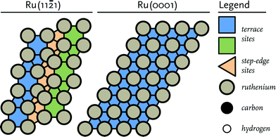 | ||
Fig. 1 Schematic representation of (left) the corrugated Ru(11![[2 with combining macron]](https://www.rsc.org/images/entities/char_0032_0304.gif) 1) surface and (right) the close-packed Ru(0001) terrace surface. 1) surface and (right) the close-packed Ru(0001) terrace surface. | ||
Ionic relaxation was carried out by the conjugate gradient method. During geometry optimization, all the degrees of freedom of the atoms in the slab as well as the adsorbed species were relaxed. To determine transition states, the nudged elastic band (NEB) method as developed by Jónsson et al. was employed.52 The initial images between the optimized initial and final states were obtained via linear interpolation. The transition state was confirmed to be a saddle point on the electronic energy surface by means of frequency analysis. Within VASP, this frequency analysis is performed by constructing a Hessian matrix using the finite difference approach. We only considered the frequencies of the adsorbed species within this analysis as the contribution of the metal atoms can be neglected. Prior to investigating the location and properties of the transition states, the structure and energetics of a large number of adsorption models of reactants, intermediates and products were determined. Based on these results, the initial guesses for the transition states were constructed.
Results and discussion
DFT calculations
DFT calculations will be presented for the elementary reaction steps relevant to the carbide as well as the CO insertion mechanism of the Fischer–Tropsch reaction. The main groups of reactions studied are (i) CO dissociation, (ii) C hydrogenation to CHx intermediate and CH4, (iii) CHx–CHx coupling, (iv) CHx–CHx hydrogenation, (v) CHx–CO coupling, (vi) CHxCHyO hydrogenation, (vii) CHxCHy–O scission and (viii) O hydrogenation to H2O. For the carbide mechanism, reactions of groups (i), (ii), (iii), (iv) and (viii) are relevant. The CO insertion mechanism is covered by reaction of groups (i), (v), (vi), (vii) and (viii). We did not explore oxygen removal via CO2 formation, because the CO2 selectivity for Ru catalysts in the FT reaction is low.13,53,54CO dissociation
The energy barriers for CO dissociation are given in Table 1 and correspond well with values reported before for the stepped Ru(11![[2 with combining macron]](https://www.rsc.org/images/entities/char_0032_0304.gif) 1) surface.23 Direct dissociation of CO is the preferred route, because the hydrogen-assisted route involves the thermodynamically unfavourable formyl intermediate, resulting in a much higher overall barrier for CH formation.
1) surface.23 Direct dissociation of CO is the preferred route, because the hydrogen-assisted route involves the thermodynamically unfavourable formyl intermediate, resulting in a much higher overall barrier for CH formation.
![[2 with combining macron]](https://www.rsc.org/images/entities/char_0032_0304.gif) 1). The reported forward and reverse energies are in relation to the most stable states found for the reactants and products
1). The reported forward and reverse energies are in relation to the most stable states found for the reactants and products
| Index | Elementary reaction | Forward Eact (kJ mol−1) | Backward Eact (kJ mol−1) |
|---|---|---|---|
| 1 | CO* + * → C* + O* | 65 | 90 |
| 2 | C* + H* → CH* + * | 40 | 39 |
| 3 | CH* + H* → CH2* + * | 75 | 37 |
| 4 | CH2* + H* → CH3* + * | 57 | 47 |
| 5 | CH3* + H* → CH4 + 2* | 94 | 57 |
C hydrogenation to CH4
Hydrogenation of adsorbed C to CH4 has been investigated for the Ru(11![[2 with combining macron]](https://www.rsc.org/images/entities/char_0032_0304.gif) 1) surface before.36 Here, we carried out these calculations at the same computational accuracy as for the other elementary reaction steps. The forward and backward activation energies for the consecutive hydrogenation steps of CHx (x = 0–3) to CHy (y = 1–4) are listed in Table 1.
1) surface before.36 Here, we carried out these calculations at the same computational accuracy as for the other elementary reaction steps. The forward and backward activation energies for the consecutive hydrogenation steps of CHx (x = 0–3) to CHy (y = 1–4) are listed in Table 1.
The corresponding initial, transition and final states for these reactions are given in the ESI† (Table S1). The activation energies are with respect to the most stable adsorption site of the reacting surface adsorbates. In analogy with results for other transition metals, C hydrogenation to CH is relatively facile. For Ru(11![[2 with combining macron]](https://www.rsc.org/images/entities/char_0032_0304.gif) 1), it is slightly endothermic. Further hydrogenation to CH2 (methylidene) is more difficult (Eact = 75 kJ mol−1) and endothermic by 38 kJ mol−1. This implies that at reasonable reaction temperatures surface CH2 and its hydrogenation products are much less abundant than C and CH surface intermediates. The barrier for the endothermic CH3 (methyl) formation is 57 kJ mol−1. The barrier for CH4 formation, which involves a single elementary reaction step recombining CH3 and H over a single Ru atom, has the highest barrier among the CHx hydrogenation steps (94 kJ mol−1).
1), it is slightly endothermic. Further hydrogenation to CH2 (methylidene) is more difficult (Eact = 75 kJ mol−1) and endothermic by 38 kJ mol−1. This implies that at reasonable reaction temperatures surface CH2 and its hydrogenation products are much less abundant than C and CH surface intermediates. The barrier for the endothermic CH3 (methyl) formation is 57 kJ mol−1. The barrier for CH4 formation, which involves a single elementary reaction step recombining CH3 and H over a single Ru atom, has the highest barrier among the CHx hydrogenation steps (94 kJ mol−1).
CHx + CHy coupling reactions
A total of 10 reactions between CHx species were considered for carbon–carbon bond formation to describe chain growth in the carbide mechanism of the Fischer–Tropsch reaction (Table 2).![[2 with combining macron]](https://www.rsc.org/images/entities/char_0032_0304.gif) 1)
1)
| Index | Elementary reaction | Forward Eact (kJ mol−1) | Backward Eact (kJ mol−1) |
|---|---|---|---|
| 6 | C* + C* → CC* + * | 138 | 144 |
| 7 | C* + CH* → CCH* + * | 129 | 75 |
| 8 | C* + CH2* → CCH2* + * | Not found | |
| 9 | C* + CH3* → CCH3* + * | 92 | 116 |
| 10a | CH* + CH* → CHCH* + * (terrace) | 149 | 117 |
| 10b | CH* + CH* → CHCH* + * (step) | 86 | 55 |
| 11 | CH* + CH2* → CHCH2* + * | Not found | |
| 12 | CH* + CH3* → CHCH3* + * | Not found | |
| 13 | CH2* + CH2* → CH2CH2* + * | 54 | 60 |
| 14 | CH2* + CH3* → CH2CH3* + * | Not investigated | |
| 15 | CH3* + CH3* → CH3CH3* + * | Not investigated | |
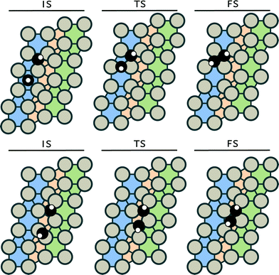
The corresponding initial, transition and final states are given in the ESI.† Reactions between CH2 and CH3 and between two CH3 (reactions 14 and 15) were not investigated, because it is well known that the interaction of the spatially extended C–H bonds in CH3 adsorbates results in repulsion, precluding C–C bond formation.55 Despite considerable efforts, we could not identify transition states for the following reactions: C + CH2, CH + CH2 and CH + CH3 coupling. We assume that these reaction will not occur on the Ru(11![[2 with combining macron]](https://www.rsc.org/images/entities/char_0032_0304.gif) 1) surface. It should be noted that these reactions have been reported to be feasible on terrace surfaces.56 For the remaining five coupling steps C + C, C + CH, CH + CH, CH2 + CH2 and C + CH3 coupling, we identified six unique transition states. For the CH + CH coupling step, two different pathways were found (see Fig. 2).
1) surface. It should be noted that these reactions have been reported to be feasible on terrace surfaces.56 For the remaining five coupling steps C + C, C + CH, CH + CH, CH2 + CH2 and C + CH3 coupling, we identified six unique transition states. For the CH + CH coupling step, two different pathways were found (see Fig. 2).
The analogous coupling reaction involving longer chains adsorbed on the surface are of the CH + CR type with R being an alkyl group. Therefore, we investigated this latter reaction step for R = CH3 in more detail in section 3.2. Table 2 shows that the barrier for CH + CH coupling is substantially lower on the step-edge site than on the terrace surface. This preference for coupling on the step-edge site is in accordance with several other works.37,57,58 Based on this insight, we investigated the other coupling reactions (reactions 6, 7, 9 and 13) on the stepped surface as well. The most facile coupling reaction occurs between two methylidene species with a barrier of 54 kJ mol−1 (reaction 6). The barrier for the other coupling reactions are higher: 86 kJ mol−1 for CH + CH, 92 kJ mol−1 for C + CH3, 129 kJ mol−1 for C + CH and 138 kJ mol−1 for coupling of two carbon adatoms (C + C).
CHxCHy hydrogenation reactions
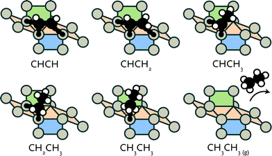
After formation of carbon–carbon bonds, higher hydrocarbons may leave the surface as olefins or paraffins (see Fig. 3). We investigated such chain-growth termination steps for CHx–CHy species. From CCH, a large number of hydrogenation routes to ethylene and ethane needs to be considered. These possibilities and the results of a reaction energy analysis are given in Table 3.![[2 with combining macron]](https://www.rsc.org/images/entities/char_0032_0304.gif) 1)
1)
| Index | Elementary reaction | Forward Eact (kJ mol−1) | Backward Eact (kJ mol−1) |
|---|---|---|---|
| 16 | CC* + H* → CCH* + * | 104 | 72 |
| 17 | CCH* + H* → CCH2* + * | 82 | 129 |
| 18 | CCH2* + H* → CCH3* + * | 19 | 4 |
| 19 | CHCH* + H* → CHCH2* + * | 83 | 46 |
| 20 | CHCH2* + H* → CHCH3* + * | 62 | 34 |
| 21 | CCH* + H* → CHCH* + * | 140 | 162 |
| 22 | CCH2* + H* → CHCH2* + * | 82 | 21 |
| 23 | CCH3* + H* → CHCH3* + * | 82 | 8 |
| 24 | CHCH2* + H* → CH2CH2* + * | 45 | 42 |
| 25 | CHCH3* + H* → CH2CH3* + * | 19 | 23 |
| 26 | CH2CH2* + H* → CH2CH3* + * | 58 | 34 |
| 27 | CH2CH3* + H* → CH3CH3* + * | 112 | 71 |
The structures of the involved stable and transition states are collected in the ESI.† Hydrogenation of CCH to CCH2 (reaction 17) and CHCH to CHCH2 (reaction 19) have very similar forward activation barriers around 82 kJ mol−1. While CCH2 formation is exothermic, CHCH2 formation is endothermic. Subsequent hydrogenation to CCH3 (reaction 18) and CHCH3 (reaction 20) proceeds with barriers of 19 and 62 kJ mol−1, respectively.
Comparatively, hydrogenation of CCH to CHCH and the reverse dehydrogenation of CHCH to CCH (reaction 21) are kinetically hindered with barriers of 140 and 162 kJ mol−1, respectively. Hydrogenation of CCH2 to CHCH2 (reaction 22) and of CCH3 to CHCH3 (reaction 23) have barriers of 82 kJ mol−1. The reverse dehydrogenation reactions are very facile with barriers of 21 and 8 kJ mol−1, respectively. This implies that CCHx intermediates are significantly more stable than the corresponding CHCHx intermediates. This difference draws similarity to the higher stability of adsorbed CH over CH2. Finally, we consider reactions that lead to formation of ethylene (reaction 24) and ethane (reactions 25, 26 and 27). Whereas ethylene formation proceeds with an activation energy of 45 kJ mol−1 and is almost thermodynamically neutral, the hydrogenation of CHCH3 to CH2CH3 and, finally, CH3CH3 is endothermic. Although the first hydrogenation step to CH2CH3 is facile and slightly exothermic, the second hydrogenation step toward ethane has to overcome a relatively high barrier of 112 kJ mol−1. It is endothermic by 41 kJ mol−1. Alternatively, adsorbed ethylene can be further hydrogenated to CH2CH3 (reaction 26). Although this reaction is facile with an activation barrier of 58 kJ mol−1, the reverse reaction is more favourable with an activation energy of 34 kJ mol−1.
CHx + CO coupling
Three different reactions between CHx species and CO were considered for chain propagation in the CO insertion mechanism (Table 4). These reactions all involve the migration of adsorbed CO to a site adjacent to the CHx adsorption site followed by C–C bond formation. Both carbon atoms in the final coupled CHx–CO species coordinate to surface Ru atoms. This strongly differs from mechanisms proposed based on homogeneous mononuclear coordination complexes for CO insertion or migration.59| Index | Elementary reaction | Forward Eact (kJ mol−1) | Backward Eact (kJ mol−1) |
|---|---|---|---|
| 28 | C* + CO* → CCO* + * | 138 | 61 |
| 29 | CH* + CO* → CHCO* + * | 148 | 44 |
| 30 | CH2* + CO* → CH2CO* + * | 155 | 36 |
| 31 | CH3* + CO* → CH3CO* + * | Not investigated | |
The corresponding initial, transition and final states are given in the ESI.† The reaction between CH3 and CO (reaction 30) was not considered due to the expected steric repulsion. The most facile CO insertion reaction is the C + CO coupling reaction (reaction 28) with a barrier of 138 kJ mol−1. The barrier for CH + CO coupling (reaction 29) and CH2 + CO coupling (reaction 30) are somewhat higher at 148 kJ mol−1 and 155 kJ mol−1, respectively. From comparison with the data in Table 2, it is immediately clear that the barriers for CO insertion are significantly higher than those for CHx + CHy coupling (Table 2). Moreover, all CO insertion reactions are strongly endothermic by at least 77 kJ mol−1, implying that the rate constants for the reverse reactions are substantially higher.
CHx–CO hydrogenation
After CO insertion, the resulting CHxCO moiety can be hydrogenated to form a CHxCHyO species. We did not consider formation of oxygenated products that can leave the surface, because their yield is usually very low under practical FT conditions. For each CHxCO* intermediate, the hydrogenation of either carbon atom was considered. This results in five different hydrogenation reactions (Table 5).![[2 with combining macron]](https://www.rsc.org/images/entities/char_0032_0304.gif) 1)
1)
| Index | Elementary reaction | Forward Eact (kJ mol−1) | Backward Eact (kJ mol−1) |
|---|---|---|---|
| 32 | CCO* + H* → CHCO* + * | 104 | 77 |
| 33 | CCO* + H* → CCHO* + * | Not found | |
| 34 | CHCO* + H* → CH2CO* + * | 95 | 41 |
| 35 | CHCO* + H* → CHCHO* + * | 68 | 7 |
| 36 | CH2CO* + H* → CH2CHO* + * | 63 | 4 |
We could not identify a transition state for CCO* hydrogenation (reaction 33). The orientation of the CCO* moiety in the step-edge site (see the ESI†) prevents hydrogenation of the carbon atom of the CO group. The most difficult hydrogenation step is that of CCO* to CHCO* (reaction 32), which involves an activation energy of 104 kJ mol−1. The other reactions, i.e. the hydrogenation of CHCO* to CH2CO, that of CHCO* to CHCHO* and finally the hydrogenation of CH2CO* to CH2CHO* proceed with lower activation energies of 95, 68 and 63 kJ mol−1, respectively. All CHxCO hydrogenation reactions are endothermic.
CHxCHy–O bond scission
For chain growth to proceed, the C–O bond in the CHxCHyO surface intermediate must first cleave. Five such elementary reaction steps were considered for which results are listed in Table 6.| Index | Elementary reaction | Forward Eact (kJ mol−1) | Backward Eact (kJ mol−1) |
|---|---|---|---|
| 37 | CCO* + * → CC* + O* | 52 | 127 |
| 38 | CHCO* + * → CCH* + O* | 92 | 163 |
| 39 | CH2CO* + * → CCH2* + O* | 77 | 248 |
| 40 | CHCHO* + * → CHCH* + O* | 72 | 225 |
| 41 | CH2CHO* + * → CHCH2* + O* | 65 | 234 |
Among these reactions, it is most easy to cleave the C–O bond in CCO* with an activation energy of 52 kJ mol−1. The C–O bond cleavage barriers for the other reactions are higher. All reactions are strongly exothermic, especially those for the partially hydrogenated fragments.
Water formation
In the FT reaction, the surface oxygen atoms deriving from CO dissociation are predominantly removed as water (Table 7). Water formation can proceed via two mechanisms, both involving intermediate OH formation from O and H (reaction 42) followed by either direct hydrogenation of OH to H2O (reaction 43) or via proton migration between two OH species to form H2O and O (reaction 44). The first hydrogenation step to produce adsorbed OH has a relatively high barrier of 97 kJ mol−1. The barrier for water formation via OH hydrogenation is 89 kJ mol−1. Comparatively, the reaction between two hydroxyl groups is much more facile with a barrier of 54 kJ mol−1. This suggests that water formation by reaction of two OH groups to H2O and adsorbed O is preferred.| Index | Elementary reaction | Forward Eact (kJ mol−1) | Backward Eact (kJ mol−1) |
|---|---|---|---|
| 42 | O* + H* → OH* + * | 97 | 49 |
| 43 | OH* + H* → H2O* + * | 89 | 15 |
| 44 | OH* + OH* → H2O* + O* + * | 54 | 11 |
Electron density difference analysis
To understand the differences in activation energies of the various elementary reaction steps, we investigated electron density differences of selected reactions. Since the use of atomic charges is not preferred as it is difficult to assign electrons to a specific atom and chemical bonding typically involves contributions of several molecular orbitals, it is more instructive to map electron density differences in space. We focus here on three important issues relevant for the FT reaction. Firstly, we address the different reactivities of terrace and stepped sites. In particular, we focus on the coupling step with the lowest activation barrier, i.e. CH + CH coupling. Secondly, we will compare CH coupling with CH and CCH3 on stepped sites, because the latter reaction is relevant for formation of C3 products. Finally, we will highlight the different adsorption strengths of ethylene and propylene on stepped sites, which explains the lower than expected C2 selectivity observed during the FT reaction.CH + CH coupling
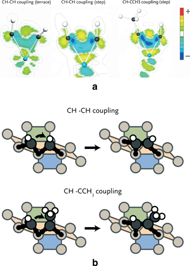
The barriers for CH + CH coupling on stepped and terrace sites of the Ru(11![[2 with combining macron]](https://www.rsc.org/images/entities/char_0032_0304.gif) 1) (Fig. 2) are 86 and 149 kJ mol−1, respectively. Fig. 4a shows the electron density shifts that result from the formation of C–C bonds between two CH surface species in the corresponding transition state complexes. To determine these, the electron density distributions of the two separate CH fragments and the empty surface were subtracted from the electron density distribution of the transition state complex. It is seen that in the transition state for the stepped site the electron density between the two C atoms is lowered and shifts to the metal atom. The corresponding shift in electron density for the transition state formation on the terrace site is smaller. There are two reasons for this difference. Firstly, it relates to the specific geometry of the transition state complex on the stepped site, which results in increased overlap between the bonding C–C orbitals and the metal d-band. Secondly, the coordinative unsaturation of the surface metal atoms is higher for the stepped than for the terrace surface. The decrease in electron density between the two CH fragments by electron donation to the metal center results in decreased Pauli repulsion and, accordingly, in lower activation energy for coupling.
1) (Fig. 2) are 86 and 149 kJ mol−1, respectively. Fig. 4a shows the electron density shifts that result from the formation of C–C bonds between two CH surface species in the corresponding transition state complexes. To determine these, the electron density distributions of the two separate CH fragments and the empty surface were subtracted from the electron density distribution of the transition state complex. It is seen that in the transition state for the stepped site the electron density between the two C atoms is lowered and shifts to the metal atom. The corresponding shift in electron density for the transition state formation on the terrace site is smaller. There are two reasons for this difference. Firstly, it relates to the specific geometry of the transition state complex on the stepped site, which results in increased overlap between the bonding C–C orbitals and the metal d-band. Secondly, the coordinative unsaturation of the surface metal atoms is higher for the stepped than for the terrace surface. The decrease in electron density between the two CH fragments by electron donation to the metal center results in decreased Pauli repulsion and, accordingly, in lower activation energy for coupling.
CH + CH vs. CH + CCH3 coupling
We found that methylidyne (CH) coupling to the CCH3 surface intermediate (Fig. 4b) proceeds with lower barrier than CH coupling to another CH species (65 vs. 86 kJ mol−1). In Fig. 4a, the electron density shifts for C–C bond formation are shown. It can be seen that in the transition state for CH + CCH3 coupling more electron density is shifted from between the CH and CCH3 species to the metal atom relative to the CH–CH case. This difference is caused by the σ-donating effect of the methyl group. Consequently, the Pauli repulsion between CH and CCH3 is lower than between two CH fragments, explaining why the barrier for coupling of the former two fragments is lower.Ethylene vs. propylene desorption
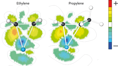
Ethylene and propylene adsorb ‘side-on’ on a single Ru atom through interaction with their C![[double bond, length as m-dash]](https://www.rsc.org/images/entities/char_e001.gif) C double bonds. The adsorption energies of ethylene and propylene are 120 and 100 kJ mol−1, respectively. The electron density shifts upon olefin adsorption are shown in Fig. 5. Here, the electron density difference is determined by subtracting the electron density of the adsorbate in the geometry it has in the adsorbed state and the empty surface from the electron density of the surface–adsorbate complex. The difference in electron density for ethylene is larger than for propylene. The reason for the decreased electron density shift of the double bond in adsorbed propylene is the π-accepting nature of the CH3 substituent. This results in weaker adsorption of propylene as compared to ethylene. We expect that the stronger interaction of ethylene will result in increased surface residence time of this fragment, which increases the probability of its chain growth relative to desorption and hydrogenation as compared with that of its higher carbon number analogues.
C double bonds. The adsorption energies of ethylene and propylene are 120 and 100 kJ mol−1, respectively. The electron density shifts upon olefin adsorption are shown in Fig. 5. Here, the electron density difference is determined by subtracting the electron density of the adsorbate in the geometry it has in the adsorbed state and the empty surface from the electron density of the surface–adsorbate complex. The difference in electron density for ethylene is larger than for propylene. The reason for the decreased electron density shift of the double bond in adsorbed propylene is the π-accepting nature of the CH3 substituent. This results in weaker adsorption of propylene as compared to ethylene. We expect that the stronger interaction of ethylene will result in increased surface residence time of this fragment, which increases the probability of its chain growth relative to desorption and hydrogenation as compared with that of its higher carbon number analogues.
Reaction energy diagrams
We constructed reaction energy diagrams based on the elementary reaction steps explored in the DFT study (Tables 2–6). Fig. 6 shows the reaction energy diagram for formation of ethylene and water from CO and H2 in the carbide mechanism. For comparison, this diagram also contains the reaction pathway that leads to methane and water from synthesis gas. The ZPE (zero-point energy)-corrected overall reaction energies for ethylene and methane formation are −212 and −217 kJ mol−1, respectively, which are close to thermodynamic data.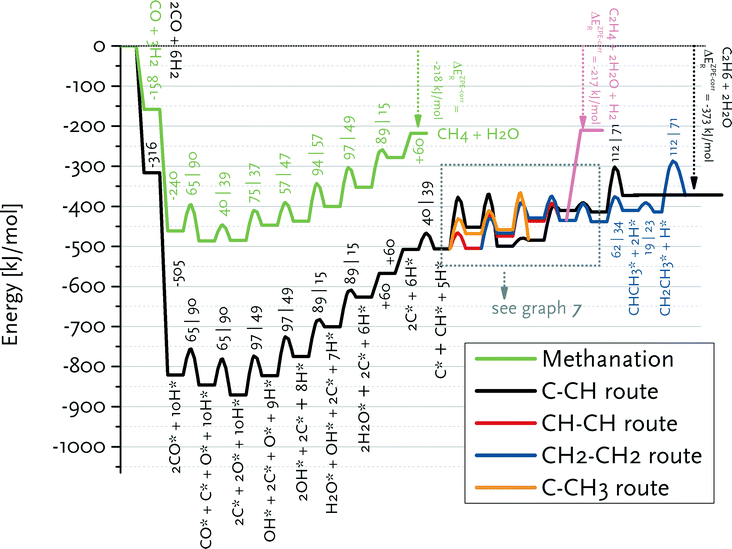 | ||
| Fig. 6 Reaction energy diagram for ethane, ethylene and methane formation from carbon monoxide and hydrogen. A straight line indicates an adsorption/desorption reaction, whereas the parabolic lines denote a surface elementary reaction step. The adsorption/desorption energies as well as the forward and backward activation energies are given. The detailed pathways for the reactions from adsorbed C* and CH* to CH2CH3* and CHCH2* are given in Fig. 7. | ||
Fig. 7 shows that the preferred pathway for formation of adsorbed CH2CH2 involves CH + CH coupling followed by hydrogenation to CH2CH2. The C + CH coupling reaction is very unfavourable with a forward barrier of 129 kJ mol−1. The overall barrier for C + CH3 coupling is also unfavourable, because CH3 formation is endothermic and the barrier for its coupling to C is also relatively high. Further reaction of CCH3 to CH2CH2 would involve the endothermic dehydrogenation to CCH2, followed by the endothermic hydrogenation to CHCH2 (Eact = 61 kJ mol−1) and the nearly thermoneutral hydrogenation step to adsorbed CH2CH2 with a barrier of 45 kJ mol−1. Although coupling of two CH2 fragments is facile, their formation is strongly endothermic. As C and CH are the most stable surface intermediates yet coupling reactions between C adsorbates are unfavourable, CH is predicted to be the dominant chain propagation surface intermediate. The desorption energy of adsorbed ethylene is 120 kJ mol−1. The further hydrogenation of ethylene to ethane is included in Fig. 6. The most difficult step towards ethane formation is the hydrogenative desorption of CH2CH3 to CH3CH3 with an activation energy of 112 kJ mol−1.
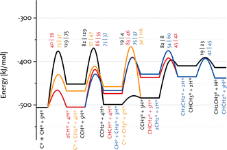 | ||
Fig. 7 Enlarged part of the reaction energy diagram showing various routes to ethane and ethylene formation. All data refer to the Ru(11![[2 with combining macron]](https://www.rsc.org/images/entities/char_0032_0304.gif) 1) surface. 1) surface. | ||
Fig. 8 summarizes the pathways relevant to the CO insertion mechanism leading towards CHCH* formation in a reaction energy diagram. Similar to the carbide mechanism, the growing chain is initiated from adsorbed C*, which requires CO dissociation. The most favourable path involves C + CO coupling followed by CC formation and its hydrogenation to CHCH. As CH together with C are the most stable CHx surface intermediates, we also considered CH + CO coupling. The overall barrier to CCH* formation via this route is higher because of the relatively low stability of the CHCO intermediate. This pathway is nevertheless relevant to the CO insertion mechanism, because only the first coupling (i.e., C2 formation) can proceed via C + CO. Growth beyond C2 surface species will proceed via CR + CO with R being an alkyl group, for which the barrier of the CH + CO coupling is a reasonable estimate. Although the barrier for CH2 + CO coupling is only slightly higher than for the other considered coupling reactions, the lower surface stability of CH2vs. C and CH results in a substantially higher overall barrier towards the product without the O atom, namely CH2C. The alternative pathway via CH2CHO is even less favourable.
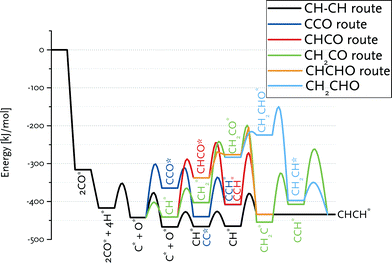 | ||
| Fig. 8 Reaction energy diagram for CHCH* formation from CO and H2. The various routes in the CO insertion mechanism are compared to the CH–CH route in the carbide mechanism. | ||
Comparison of these paths with that of chain growth via CH + CH coupling (Fig. 8) clearly shows that the overall barrier for CHCH formation via the carbide mechanism (63 kJ mol−1) is substantially lower than the preferred pathway via CO insertion (138 kJ mol−1). The CO insertion route is unfavourable because of the endothermicity of the CHx + CO coupling (Table 4) as well as of subsequent CHxCO hydrogenation reactions (Table 5).
Fig. 9 shows the reaction energy diagram for propylene formation within the carbide mechanism. This diagram involves CH as the main inserting species in view of the low barrier for CH insertion into CCH3 species as compared to the most favourable CH + CH pathway for C2 formation. Fig. 9 also shows that further growth of the CHCH2 surface intermediate is favoured over formation and desorption of ethylene. This already indicates that the computed kinetics are conducive to formation of long chain hydrocarbon products on this surface. Compared to the C2 case, there will be less competition between chain growth of a C3 intermediate and desorption of propylene, because the desorption energy of propylene is lower than that of ethylene. We expect that the adsorption energy of longer olefins will be very similar to that of propylene. Qualitatively, the different balances between chain growth and product desorption for C2 and higher carbon number surface intermediates explains the experimentally observed C2 selectivity below that of the ASF distribution for the higher hydrocarbon products.12
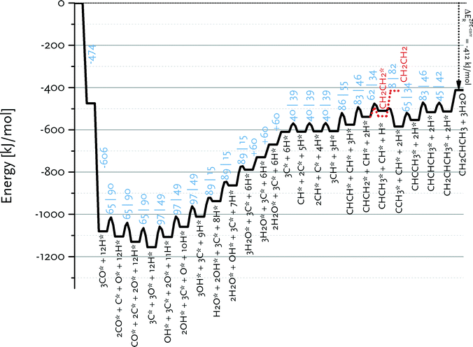 | ||
Fig. 9 Reaction energy diagram for propylene from carbon monoxide and hydrogen. All data are for the Ru(11![[2 with combining macron]](https://www.rsc.org/images/entities/char_0032_0304.gif) 1) surface. 1) surface. | ||
Carbide vs. CO insertion mechanism
An important prerequisite for obtaining long hydrocarbon chains in the Fischer–Tropsch reaction is fast chain growth rate vs. chain-growth termination rate. This condition will lead to high values for the chain-growth probability α, defined as | (1) |
We have earlier deduced explicit expressions for the chain-growth probability within the framework of lumped-sum kinetics for both the carbide and the CO insertion mechanism.25,26,60 For the carbide mechanism, the expression is
 | (2) |
 | (3) |
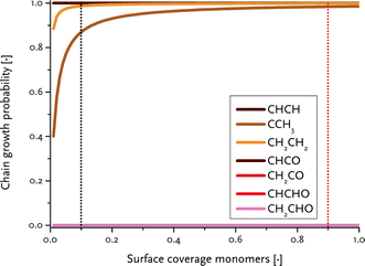
To determine the reaction rate constants for the chain growth steps in eqn (2) and (3), we determined the highest overall barrier along the reaction pathway with respect to the energy of the monomeric building block. These building blocks are surface CH and CO adsorbates, respectively, for the carbide and CO insertion mechanisms (details on other reaction steps and further assumptions are in the ESI†). The rate constants are listed in Table 8. Eqn (2) and (3) show that the chain-growth probability will also depend on the surface coverage of the chain propagating intermediate. To understand whether the proposed mechanisms can lead to desired Fischer–Tropsch products, we simply determined the chain-growth probability as a function of these surface coverages. The C1 coverage is reported to be below 10% under FTS conditions, whereas the CO surface coverage may be assumed to be 90% or higher.11,26,60Fig. 10 shows that the chain-growth probability for the CO insertion mechanism is negligible irrespective of the CO coverage. This analysis implies that CHx hydrogenation to methane is strongly preferred over chain propagation with CO as the building block. On the contrary, all three pathways with reasonable overall barrier for chain growth in the carbide mechanism, that is CH + CH coupling (96 kJ mol−1), CH2 + CH2 coupling (126 kJ mol−1) and C + CH3 coupling (136 kJ mol−1) give greater than zero values for the chain-growth probability. At typical C1 coverage below 10%, the chain-growth probability is highest for the CH + CH coupling pathway.
| Route | Mechanism | k p [mol s−1] | k t [mol s−1] |
|---|---|---|---|
| CHCH | Carbide | 6.79 × 10² | 5.88 × 10⁻⁴ |
| CCH3 | Carbide | 4.51 × 10⁻¹ | 5.88 × 10⁻⁴ |
| CH2CH2 | Carbide | 3.94 × 10⁻² | 5.88 × 10⁻⁴ |
| CHCO | CO insertion | 1.74 × 10⁻⁸ | 5.88 × 10⁻⁴ |
| CHCHO | CO insertion | 1.00 × 10⁻¹² | 5.88 × 10⁻⁴ |
| CH2CO | CO insertion | 3.80 × 10⁻¹³ | 5.88 × 10⁻⁴ |
| CH2CHO | CO insertion | 5.84 × 10⁻¹⁷ | 5.88 × 10⁻⁴ |
Conclusions
DFT calculations were carried out for elementary reaction steps of carbide and CO insertion mechanisms relevant to the Fischer–Tropsch reaction on the stepped Ru(11![[2 with combining macron]](https://www.rsc.org/images/entities/char_0032_0304.gif) 1) surface. Activation barriers and reaction energies were determined for CO dissociation, C hydrogenation, CHx + CHy and CHx + CO coupling, hydrogenation reactions of the surface intermediates, CHxCHy–O bond scission and O hydrogenation, which lead to formation of methane, higher hydrocarbons including olefins and alkanes and water. The preferred path for propagation in the carbide mechanism is CH + CH coupling. Higher hydrocarbons are formed by CH insertion into a CCH3 (or C(CH2)nCH3 equivalents) intermediate, which is formed via a sequence of hydrogenation–dehydrogenation steps of adsorbed CHCH. Coupling reactions of the type CH + CCH3 are more favourable than CH + CH coupling, which is attributed to the σ-donating effect of the alkyl substituent. CH + CH coupling is much more favourable n the stepped site of the Ru(11
1) surface. Activation barriers and reaction energies were determined for CO dissociation, C hydrogenation, CHx + CHy and CHx + CO coupling, hydrogenation reactions of the surface intermediates, CHxCHy–O bond scission and O hydrogenation, which lead to formation of methane, higher hydrocarbons including olefins and alkanes and water. The preferred path for propagation in the carbide mechanism is CH + CH coupling. Higher hydrocarbons are formed by CH insertion into a CCH3 (or C(CH2)nCH3 equivalents) intermediate, which is formed via a sequence of hydrogenation–dehydrogenation steps of adsorbed CHCH. Coupling reactions of the type CH + CCH3 are more favourable than CH + CH coupling, which is attributed to the σ-donating effect of the alkyl substituent. CH + CH coupling is much more favourable n the stepped site of the Ru(11![[2 with combining macron]](https://www.rsc.org/images/entities/char_0032_0304.gif) 1) surface than on the terrace site. The difference originates from the stronger overlap of the forming π-bonds between the CH fragments with the partially empty d-orbitals of the more reactive metal surface atoms, resulting in decreased Pauli repulsion. The preferred coupling pathway in the CO insertion mechanism involves the reaction between C and CO followed by facile C–O bond cleavage in CCO. All the CHxCO intermediates are relatively unstable on the surface as compared to CHx and CO, so that the overall barriers for chain-growth via CO-insertion are much higher than those via CH + CH coupling. The kinetic consequence of this difference is that high chain-growth rate constants are predicted for the carbide mechanism, whereas these are very low for the CO insertion mechanism. This kinetic analysis predicts methane to be the main product during CO hydrogenation within the CO insertion mechanism. With kinetic parameters computed for the carbide mechanism, high chain-growth probability is predicted. The carbide mechanism explains the formation of long hydrocarbon chains on the stepped Ru surface.
1) surface than on the terrace site. The difference originates from the stronger overlap of the forming π-bonds between the CH fragments with the partially empty d-orbitals of the more reactive metal surface atoms, resulting in decreased Pauli repulsion. The preferred coupling pathway in the CO insertion mechanism involves the reaction between C and CO followed by facile C–O bond cleavage in CCO. All the CHxCO intermediates are relatively unstable on the surface as compared to CHx and CO, so that the overall barriers for chain-growth via CO-insertion are much higher than those via CH + CH coupling. The kinetic consequence of this difference is that high chain-growth rate constants are predicted for the carbide mechanism, whereas these are very low for the CO insertion mechanism. This kinetic analysis predicts methane to be the main product during CO hydrogenation within the CO insertion mechanism. With kinetic parameters computed for the carbide mechanism, high chain-growth probability is predicted. The carbide mechanism explains the formation of long hydrocarbon chains on the stepped Ru surface.
Acknowledgements
NWO is acknowledged for providing access to the supercomputer facilities.Notes and references
- C. Song, Catal. Today, 2006, 115, 2 CrossRef CAS PubMed.
- F. Fischer and H. Tropsch, Brennst.-Chem., 1923, 4, 276 CAS.
- G. A. Somorjai, Introduction to Surface Chemistry and Catalysis, Wiley, New York, 1994 Search PubMed.
- R. B. Anderson, The Fischer-Tropsch Synthesis, Academic Press, New York, 1984 Search PubMed.
- R. A. van Santen, I. M. Ciobîcă, E. van Steen and M. M. Ghouri, in Adv. Catal., ed. C. G. Bruce and K. Helmut, Academic Press, 2011, vol. 54, pp. 127–187 Search PubMed.
- P. Biloen and W. M. H. Sachtler, in Adv. Catal., ed. H. P. D. D. Eley and B. W. Paul, Academic Press, 1981, vol. 30, pp. 165–216 Search PubMed.
- A. T. Bell, Catal. Rev.: Sci. Eng., 1981, 23, 203–232 CAS.
- R. A. van Santen, M. M. Ghouri, S. Shetty and E. J. M. Hensen, Catal. Sci. Technol., 2011, 1, 891–911 CAS.
- A. P. Steynberg, in Stud. Surf. Sci. Catal., ed. S. André and D. Mark, Elsevier, 2004, vol. 152, pp. 1–63 Search PubMed.
- A. J. Markvoort, R. A. van Santen, P. A. J. Hilbers and E. J. M. Hensen, Angew. Chem., Int. Ed., 2012, 9, 9012–9019 Search PubMed.
- R. A. van Santen, A. J. Markvoort, M. M. Ghouri, P. A. J. Hilbers and E. J. M. Hensen, J. Phys. Chem. C, 2013, 117, 4488–4504 CAS.
- G. P. Van Der Laan and A. A. C. M. Beenackers, Catal. Rev.: Sci. Eng., 1999, 41, 255–318 CAS.
- M. Claeys and E. van Steen, in Stud. Surf. Sci. Catal., ed. S. André and D. Mark, Elsevier, 2004, vol. 152, pp. 601–680 Search PubMed.
- S. Novak, R. J. Madon and H. Suhl, J. Catal., 1982, 77, 141–151 CrossRef CAS.
- E. Iglesia, S. C. Reyes, R. J. Madon and S. L. Soled, in Adv. Catal., ed. H. P. D. D. Eley and B. W. Paul, Academic Press, 1993, vol. 39, pp. 221–302 Search PubMed.
- E. W. Kuipers, I. H. Vinkenburg and H. Oosterbeek, J. Catal., 1995, 152, 137–146 CrossRef CAS.
- E. W. Kuipers, C. Scheper, J. H. Wilson, I. H. Vinkenburg and H. Oosterbeek, J. Catal., 1996, 158, 288–300 CrossRef CAS.
- B. W. Wojciechowski, Catal. Rev.: Sci. Eng., 1988, 30, 629–702 CAS.
- J. Abbot and B. W. Wojciechowski, Can. J. Chem. Eng., 1988, 66, 817–824 CrossRef CAS.
- B. Sarup and B. W. Wojciechowski, Can. J. Chem. Eng., 1989, 67, 620–627 CrossRef CAS.
- M. Ojeda, R. Nabar, A. U. Nilekar, A. Ishikawa, M. Mavrikakis and E. Iglesia, J. Catal., 2010, 272, 287–297 CrossRef CAS PubMed.
- B. T. Loveless, C. Buda, M. Neurock and E. Iglesia, J. Am. Chem. Soc., 2013, 135, 6107–6121 CrossRef CAS PubMed.
- S. Shetty and R. A. van Santen, Catal. Today, 2011, 171, 168–173 CrossRef CAS PubMed.
- S. G. Shetty, A. P. J. Jansen and R. A. van Santen, J. Phys. Chem. C, 2008, 112, 14027–14033 CAS.
- R. A. Van Santen, A. J. Markvoort, I. A. W. Filot, M. M. Ghouri and E. J. M. Hensen, Phys. Chem. Chem. Phys., 2013, 15, 17038–17063 RSC.
- R. A. van Santen and A. J. Markvoort, ChemCatChem, 2013, 5, 3384–3397 CrossRef CAS.
- T. Zubkov, G. A. Morgan Jr and J. T. Yates Jr, Chem. Phys. Lett., 2002, 362, 181–184 CrossRef CAS.
- M. Mavrikakis, M. Bäumer, H. J. Freund and J. K. Nørskov, Catal. Lett., 2002, 81, 153–156 CrossRef CAS.
- B. Hammer and J. K. Nørskov, in Adv. Catal., ed. H. K. Bruce and C. Gates, Academic Press, 2000, vol. 45, pp. 71–129 Search PubMed.
- Z.-P. Liu and P. Hu, J. Am. Chem. Soc., 2002, 124, 11568–11569 CrossRef CAS PubMed.
- I. M. Ciobica and R. A. van Santen, J. Phys. Chem. B, 2003, 107, 3808–3812 CrossRef CAS.
- S. Shetty, A. P. J. Jansen and R. A. van Santen, J. Am. Chem. Soc., 2009, 131, 12874–12875 CrossRef CAS PubMed.
- F. Fischer and H. Tropsch, Brennst.-Chem., 1926, 7, 79–116 Search PubMed.
- X.-Q. Gong, R. Raval and P. Hu, J. Chem. Phys., 2005, 122, 024711 CrossRef PubMed.
- I. M. Ciobica, F. Frechard, R. A. van Santen, A. W. Kleyn and J. Hafner, J. Phys. Chem. B, 2000, 104, 3364–3369 CrossRef CAS.
- S. G. Shetty, A. P. J. Jansen and R. A. van Santen, J. Phys. Chem. C, 2010, 114, 22630–22635 CAS.
- J. Cheng, P. Hu, P. Ellis, S. French, G. Kelly and M. C. Lok, J. Phys. Chem. C, 2008, 112, 6082–6086 CAS.
- M. Zhuo, K. F. Tan, A. Borgna and M. Saeys, J. Phys. Chem. C, 2009, 113, 8357–8365 CAS.
- M. Zhuo, A. Borgna and M. Saeys, J. Catal., 2013, 297, 217–226 CrossRef CAS PubMed.
- P. M. Maitlis, H. C. Long, R. Quyoum, M. L. Turner and Z.-Q. Wang, Chem. Commun., 1996, 1–8 RSC.
- R. Quyoum, V. Berdini, M. L. Turner, H. C. Long and P. M. Maitlis, J. Catal., 1998, 173, 355–365 CrossRef CAS.
- M. L. Turner, N. Marsih, B. E. Mann, R. Quyoum, H. C. Long and P. M. Maitlis, J. Am. Chem. Soc., 2002, 124, 10456–10472 CrossRef CAS PubMed.
- X.-Q. Gong, R. Raval and P. Hu, Surf. Sci., 2004, 562, 247–256 CrossRef CAS PubMed.
- X.-Q. Gong, R. Raval and P. Hu, Mol. Phys., 2004, 102, 993–1000 CrossRef CAS.
- A. Michaelides, A. Alavi and D. A. King, J. Am. Chem. Soc., 2003, 125, 2746–2755 CrossRef CAS PubMed.
- T. W. Zhu, P. W. van Grootel, I. A. W. Filot, S. G. Sun, R. A. van Santen and E. J. M. Hensen, J. Catal., 2013, 297, 227–235 CrossRef CAS PubMed.
- G. Kresse and J. Furthmüller, Comput. Mater. Sci., 1996, 6, 15–50 CrossRef CAS.
- G. Kresse and J. Hafner, Phys. Rev. B: Condens. Matter Mater. Phys., 1994, 49, 14251 CrossRef CAS.
- J. P. Perdew, K. Burke and M. Ernzerhof, Phys. Rev. Lett., 1996, 77, 3865 CrossRef CAS.
- P. E. Blöchl, Phys. Rev. B: Condens. Matter Mater. Phys., 1994, 50, 17953 CrossRef.
- G. Kresse and J. Joubert, Phys. Rev. B: Condens. Matter Mater. Phys., 1999, 59, 1758 CrossRef CAS.
- G. Henkelman and H. Jónsson, J. Chem. Phys., 2000, 113, 9978–9985 CrossRef CAS PubMed.
- P. J. Lunde and F. L. Kester, Ind. Eng. Chem. Process Des. Dev., 1974, 13, 27–33 CAS.
- V. Pendyala, W. Shafer and B. Davis, Catal. Lett., 2013, 143, 895–901 CrossRef CAS PubMed.
- C. Zheng, Y. Apeloig and R. Hoffmann, J. Am. Chem. Soc., 1988, 110, 749–774 CrossRef CAS.
- Z.-X. Chen, H. A. Aleksandrov, D. Basaran and N. Rösch, J. Phys. Chem. C, 2010, 114, 17683–17692 CAS.
- J. Chen and Z.-P. Liu, J. Am. Chem. Soc., 2008, 130, 7929–7937 CrossRef CAS PubMed.
- J. Cheng, X.-Q. Gong, P. Hu, C. M. Lok, P. Ellis and S. French, J. Catal., 2008, 254, 285–295 CrossRef CAS PubMed.
- P. W. N. M. van Leeuwen, in Homogeneous Catalysis, Springer, Netherlands, 2004, pp. 125–138 Search PubMed.
- R. A. van Santen, M. Ghouri and E. M. J. Hensen, Phys. Chem. Chem. Phys., 2014, 16, 10041–10058 RSC.
Footnote |
| † Electronic supplementary information (ESI) available: Geometries and energies of the initial, transition and final states used in the electronic structure calculations. See DOI: 10.1039/c4cy00483c |
| This journal is © The Royal Society of Chemistry 2014 |

