 Open Access Article
Monolithic cells for solar fuels†
Jan
Rongé
a,
Tom
Bosserez
a,
David
Martel
b,
Carlo
Nervi
c,
Luca
Boarino
d,
Francis
Taulelle
a,
Gero
Decher
b,
Silvia
Bordiga
c and
Johan A.
Martens
*a
aKU Leuven, Centre for Surface Chemistry and Catalysis, Kasteelpark Arenberg 23/2461, B-3001 Leuven, Belgium. E-mail: Johan.Martens@biw.kuleuven.be; Fax: +3216 32 19 98; Tel: +3216 32 16 10
bUniversity of Strasbourg, Institut Charles Sadron, Rue du Loess 23, F-67000 Strasbourg, France
cUniversity of Torino, Nanostructured Interfaces and Surfaces, Via Quarello 15, I-10135 Torino, Italy
dIstituto Nazionale di Ricerca Metrologica, Strada delle Cacce 91, I-10135 Torino, Italy
First published on 14th February 2014
Abstract
Hybrid energy generation models based on a variety of alternative energy supply technologies are considered the best way to cope with the depletion of fossil energy resources and to limit global warming. One of the currently missing technologies is the mimic of natural photosynthesis to convert carbon dioxide and water into chemical fuel using sunlight. This idea has been around for decades, but artificial photosynthesis of organic molecules is still far away from providing real-world solutions. The scientific challenge is to perform in an efficient way the multi-electron transfer reactions of water oxidation and carbon dioxide reduction using holes and single electrons generated in an illuminated semiconductor. In this tutorial review the design of photoelectrochemical (PEC) cells that combine solar water oxidation and CO2 reduction is discussed. In such PEC cells simultaneous transport and efficient use of light, electrons, protons and molecules has to be managed. It is explained how efficiency can be gained by compartmentalisation of the water oxidation and CO2 reduction processes by proton exchange membranes, and monolithic concepts of artificial leaves and solar membranes are presented. Besides transferring protons from the anode to the cathode compartment the membrane serves as a molecular barrier material to prevent cross-over of oxygen and fuel molecules. Innovative nano-organized multimaterials will be needed to realise practical artificial photosynthesis devices. This review provides an overview of synthesis techniques which could be used to realise monolithic multifunctional membrane-electrode assemblies, such as Layer-by-Layer (LbL) deposition, Atomic Layer Deposition (ALD), and porous silicon (porSi) engineering. Advances in modelling approaches, electrochemical techniques and in situ spectroscopies to characterise overall PEC cell performance are discussed.
Key learning points(1) The management of light, reagents, protons, electrons and reaction products in photoelectrochemical cells.(2) The functions and interaction of semiconductors and co-catalysts. (3) The most promising cell concepts existing today, and potential designs for the future. (4) Methods to synthesise cell components. (5) Methods to characterise photoelectrochemical cells and their components. |
Introduction
The reduction of CO2 emissions and the quest for sustainable energy are top priorities on the world's strategic research agenda. Sunlight is an abundant renewable energy source. About 105 TW is delivered to the Earth's surface and 1.2 hours of sunlight correspond to the global energy consumption for a whole year. Drawbacks of sunlight are its diffuse and discontinuous nature necessitating its conversion into a more convenient form of energy. Photovoltaics (PV) is an established method to convert solar energy into electricity. Commercial PV with silicon single-junction cells currently are operated at 12–20% efficiency. Theoretical efficiencies for multi-band gap PV exceed 40% and organic PV shows great potential. For storage, however, electricity is a less convenient energy carrier. Storing energy in chemical bonds of fuel molecules is a more practical option and hydrogen is a candidate. PV systems and water electrolysis have been coupled to produce hydrogen and reach up to 18% efficiency,1 but the costly large platinum electrodes and peripherals together with the competitive price of hydrogen from conventional sources are obstacles to widespread use.2 The cost of renewable hydrogen in principle can be reduced by integrating light-harvesting and water splitting materials in a single system. The idea for such a water photoelectrolysis device is inspired by Fujishima and Honda's discovery of the water splitting properties of titanium dioxide (TiO2) in 1972.3 Incident photons on semiconductor materials such as TiO2 generate electron–hole pairs. The holes abstract electrons from water molecules and protons are reduced to hydrogen using the photogenerated electrons. Subsequent investigations led to several strategies for solar hydrogen formation using semiconductors (Fig. 1). Distinction can be made between photocatalytic and photoelectrochemical (PEC) systems. In the former, multiple suspended semiconductor nanoparticles each act as a reaction centre. In a photoelectrochemical cell (PEC cell) a semiconductor photoelectrode is submerged in aqueous solution and electrically connected to a second electrode. Initial efforts have been focused both on photocatalytic and photoelectrochemical approaches. Efficiency has been enhanced by using set-ups that are internally biased by a PV junction that is shielded from the solution, the so-called buried PV. In some cases, PV is connected with a photoelectrode to achieve a hybrid system (PV-PEC). While these PV-integrated systems achieved record efficiencies, the materials they are made of are prohibitively expensive. Therefore, in the last decade attention shifted to the realisation of devices based on earth-abundant materials that are both efficient and cost-effective.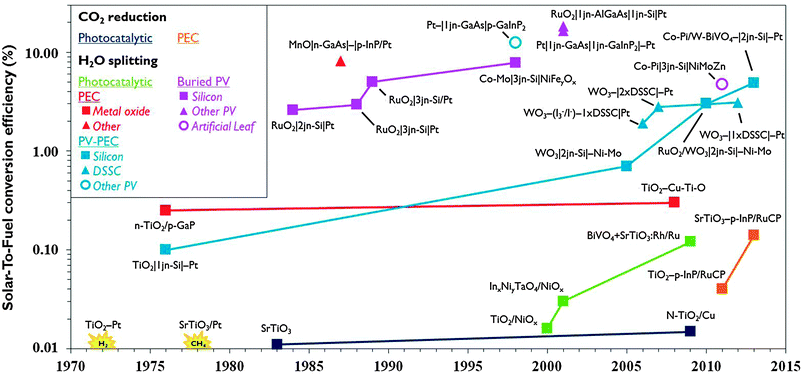 | ||
| Fig. 1 Evolution of record solar-to-fuel efficiencies of different approaches, reported in the absence of chemical or electrical bias and under (simulated) solar illumination (for additional details, see ESI†). | ||
Compared to solar hydrogen production, photoelectrochemical CO2 reduction is an even bigger challenge. Artificial photosynthesis of carbon-based fuel has advantages such as the ease of storage, especially when the products are liquid and have high volumetric energy density. One of the earliest reports of photocatalytic CO2 reduction was by Somorjai and co-workers in 1978.4 Production of methane was observed when illuminating strontium titanate semiconductor coated with platinum catalyst with UV light in the presence of water and CO2. The same year, Halmann reported formation of formic acid, formaldehyde and methanol on a p-type gallium phosphide photoelectrode.5 While PEC systems for solar hydrogen developed rapidly, the development of systems to produce carbon-based solar fuel progresses more slowly (Fig. 1). Solar-To-Fuel (STF) efficiencies are yet to exceed 0.2%, which is the solar conversion efficiency of switchgrass, a crop often quoted for biomass production.6 PV reached the market a few decades ago and water splitting PEC cells for solar hydrogen production may soon be ready for commercial development. If solar CO2 reduction is to become a viable renewable energy technology, researchers will have to join efforts in an interdisciplinary pursuit of smart reactor and electrode design.
In part A of this review critical aspects of PEC cells for CO2 reduction are discussed, with emphasis on monolithic and membrane-based designs as these are the most promising. Given the parallel with solar hydrogen production, common challenges are discussed, and illustrated with remarkable examples from recent literature. Based on the elaborated PEC cell requirements, in part B some upcoming technologies to conceive, build and characterise future electrode assemblies and PEC cells are presented. This review is restricted to semiconductor-based systems. The reader is referred to other reviews specifically dealing with homogeneous catalytic,7,8 electrochemical,8,9 biological10 and thermochemical11 strategies.
A. State-of-the-art of photoelectrochemical cells for artificial photosynthesis
1. Working principle of a PEC cell
In literature, the term PEC cell is not always consistently used. In this review, to avoid confusion, PEC cell refers to the complete reactor containing the electrode assembly and having in- and outlets for feed and reaction products, respectively. Electrode assembly refers to the heart of the PEC cell, which is the solid assembly of (photo)electrodes, co-catalysts, membrane and possibly PV. PEC cells rely on the operation of a light-sensitive material that converts incident photons into electron–hole pairs, which are consumed in oxidation–reduction reactions for production of chemical fuel. Inorganic semiconductors are currently the most promising light harvesting materials because many of them possess high stability and excellent quantum efficiency. Other photosensitive materials include dyes,7 quantum dots12 and noble metal nanoparticles,12 which may be used on their own or as sensitizers for a semiconductor. Photogenerated holes reaching the semiconductor surface can abstract electrons from water molecules that are oxidised to form molecular oxygen and protons. At pH 7 in aqueous solution the standard Nernst potential (E0) vs. Normal Hydrogen Electrode (NHE) at 25 °C and 1 atm gas pressure corresponds to:13| 2H2O → O2 + 4e− + 4H+ E0 = +0.82 V | (1) |
The photogenerated electrons and the protons generated according to eqn (1) can serve the reduction of CO2 to C1 molecules, such as carbon monoxide (CO), formic acid, formaldehyde, methanol and methane proceeding all through multielectron, multiproton reactions with the following standard potentials (vs. NHE, at pH 7 in aqueous solution, 25 °C, 1 atm gas pressure, 1 M for solutes):8,13
| CO2 + 2H+ + 2e− → CO + H2O E0 = −0.53 V | (2) |
| CO2 + 2H+ + 2e− → HCOOH E0 = −0.61 V | (3) |
| CO2 + 4H+ + 4e− → H2CO + H2O E0 = −0.48 V | (4) |
| CO2 + 6H+ + 6e− → CH3OH + H2O E0 = −0.38 V | (5) |
| CO2 + 8H+ + 8e− → CH4 + 2H2O E0 = −0.24 V | (6) |
| CO2 + e− → CO2˙− E0 = −1.90 V | (7) |
| 2H+ + 2e− → H2 E0 = −0.41 V | (8) |
The majority of scientific investigations of CO2 reduction are conducted using homogeneous catalysts dissolved in aqueous phase7 and using semiconductor particles in vapour phase.14 To reduce recombination losses and back reaction a more sophisticated setup is needed with spatial separation of water oxidation and CO2 reduction reactions on separate electrode surfaces. The most productive solar CO2 reduction system to date is such a PEC cell with separated electrodes.6 While PEC cell performance has significantly increased over the last decade especially by improvements at the electrode level, reactor design itself received relatively little attention.
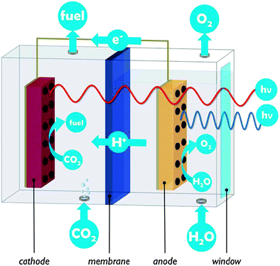
A PEC cell typically hosts two electrodes on which the water oxidation and CO2 reduction reactions take place. In the example of Fig. 2, both electrodes are photoactive and the PEC cell is divided into two compartments connected by a proton exchange membrane. PEC cells are multifunctional devices and need to control simultaneous transport of several species:
(1) Electrons (electronic transport)
(2) Protons (ionic transport)
(3) Molecules (molecular transport & barrier function)
(4) Photons (optical transparency)
The condition of electronic connection between the semiconductor and the catalytic sites responsible for oxidation and reduction reactions imposes high demands on the quality and continuity of the electrode materials. Materials that are active in photocatalysis may be less suited for application in a PEC cell, due to insufficient electrical conduction. Semiconductor nanostructures have to be synthesised with great care for crystal quality as defects and grain boundaries have a great influence on their performance. These can lead to excessive charge recombination13 but when carefully controlled, defects may be used as a doping strategy and increase light absorption.9,17 The electronic connection between the semiconductor and the catalytic centre is another critical aspect.7 In this respect, the use of insulating support materials such as mesoporous silica developed by Frei and co-workers9,12 is not obvious.
In PEC cells negative charge is conveyed by electrons, and charge balance is maintained by transport of protons from the anode to the cathode (or of hydroxide ions from the cathode to the anode, in alkaline PEC cells). Proton conduction is often more critical than electron conduction, since high ionic conductivity is more difficult to achieve. Ion conducting media have two to four orders of magnitude lower conductivity than the electron conducting components used in a PEC cell.19 Low proton and electron conductivities cause ohmic potential losses which result in lower overall efficiency.
Proton transport can occur either in the liquid or in the solid state. In a liquid electrolyte, operation at low or high pH is an obvious way to increase conductivity. When changing the acidity of the medium, the pH-dependency of energy levels of redox couples, semiconductors and catalytic centres needs to be kept in mind. The operation of a PEC cell under near-neutral pH conditions enables the use of acid- or base-sensitive materials. A buffered neutral solution is least aggressive, but poses greater challenges with respect to ion transport, because proton and hydroxide concentrations are very low (around 10−7 M).20 Here, concentration gradients due to depletion of the buffer at one electrode and accumulation at the other electrode cause a concentration overpotential.
Proton transport distance is an important aspect of PEC cell design. This can be appreciated by comparing monolithic and wired variants (Fig. 3). Nocera and co-workers built a monolithic device for solar hydrogen production with 2.5% STF efficiency.20 In this design, protons generated at the front side have to move around the electrode assembly to reach the back side. A wired PEC with facing electrodes reached a higher efficiency of 4.7% due to shorter proton transport distance and lower associated ohmic losses. Arai et al. built monolithic and wired devices for CO2 reduction, and observed efficiencies of 0.08% and 0.14%, respectively.6 While a difference in proton transport distance may contribute, those authors ascribed the efficiency difference to a slight chemical bias due to a pH gradient in their wired PEC cell. In any case, these comparative studies revealed that monolithic assemblies could profit substantially from shortened proton transport paths to the cathode side. Such shortcuts could be achieved by implementing porosity in the electrode monolith.19,20 Measures will have to be taken to avoid product cross-over through these openings, as will be discussed later on in this review.
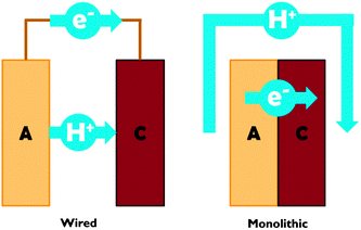 | ||
| Fig. 3 Schematic representation of proton and electron transport in wired and monolithic electrode assemblies. A = anode; C = cathode. | ||
The use of a solid electrolyte has significant advantages over liquids. Solid electrolytes can have high ionic conductivity. The proton conductivity of Nafion®, a widely used sulfonated tetrafluoroethylene based copolymer, can reach up to 10 S m−1,15 comparable to diluted H2SO4 solution.17 Since no liquid bases or acids are involved, solid electrolytes pose no environmental hazard in the event of a leak. In a solid electrolyte, the only ionic species being transported is the one consumed in the second half-reaction, which is most often the proton. The negative counter charges in the membrane are fixed, so they do not generate concentration gradients and related overpotentials are avoided. Although Nafion® is regarded to be the standard in solid electrolytes, PEC cell research could benefit from new and improved materials (including anion conducting materials) with even higher conductivities while maintaining sufficient molecular barrier function.
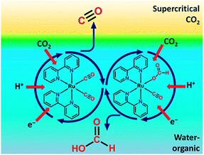 | ||
| Fig. 4 Representation of a biphasic reaction medium with a supercritical CO2 phase and liquid water-organic phase for homogeneous CO2 reduction. Reproduced with permission from ref. 22. Copyright 2013, American Chemical Society. | ||
Reaction product evacuation at either electrode can be problematic.24 Water oxidation at the anode produces molecular oxygen. When the liquid flow is insufficient for diffusional-convectional transport of oxygen, gas bubble formation will introduce overpotentials. At the cathode, reaction products may have low solubility in liquid solvents and CO formation may cause gas bubble formation as well. Operation of the PEC cell in the vapour phase instead of the liquid phase can be considered. In order to prevent cathode flooding in vapour phase PEC cells, the device could be heated above the boiling point of the organic reaction products. A temperature of 100 °C will be sufficient for most of the light organic molecules formed. A cooler/condenser unit after the PEC cell enables recovery of the liquid product and recycling of unconverted CO2. In the design of a heated PEC cell, the reduced solid electrolyte conductivity at high temperatures may be a critical issue.
In single compartment PEC cells oxidation and reduction reactions occur in the same medium. The concurrent production of oxygen gas at the anode and of reduced products at the cathode dilutes the solar fuel outlet stream of the PEC cell. This entails product workup steps, and may be dangerous since flammable and even explosive mixtures (oxygen and fuel) can be formed. In addition, back reaction of the reduced products will be catalysed, which lowers product yield. For example, the popular TiO2 semiconductor is a highly effective photocatalyst for oxidation of organic molecules.6 In PEC cells with electrodes submerged in electrolyte solution oxygen bubbles produced from water oxidation simply rise to the surface, similar to the operation of a Hoffman apparatus or Fujishima and Honda's first PEC cell.3 Since solubility of oxygen in water is very low (∼1.3 mM at standard conditions), cross-over to the cathode is said to be negligible. For the gaseous reduction products CO and H2, the same strategy can be applied to avoid back reaction. Nonetheless, cross-over may result in a significant product loss of several percent in these cases.15 Products such as formic acid readily dissolve and may reach the oxidation sites through diffusion in the liquid electrolyte.6 The introduction of a molecular barrier function such as an ion exchange membrane is a convenient way to achieve product separation by restricting transport between anode and cathode compartments to ionic intermediates. Many membranes such as Nafion® are permeable to cations and impermeable to most molecular species. Similar to direct methanol fuel cells, there is a trade-off between enhancing molecular barrier function and decreasing proton conduction.15 The use of other, porous separators (e.g. glass frit) has been investigated and these may be a low cost solution to limit convective reaction product cross-over.15
Finally, the PEC cell casing should be transparent or contain a window to allow solar illumination. High-grade optical windows can be made of fused silica or quartz. Poly(methyl methacrylate) is a low cost alternative with good light transmission. Window materials and anti-reflective coatings that were developed for PV panels can be used. For PEC cells, there is the additional prerequisite that these materials should be chemically stable in contact with electrolyte.
2. PEC photosystems
Solar fuel production is initiated by the absorption of a photon in a semiconductor. The photon excites an electron from the Valence Band (VB) to the Conduction Band (CB) and a hole is left behind in the VB. The energy difference between VB and CB is called the band gap. Absorption of a photon only occurs when its energy is at least the band gap energy of the semiconductor. A small band gap material will absorb a larger part of the solar spectrum. For solar fuel production the minimum band gap is dictated by the potential energy levels of the half reactions of water oxidation and CO2 reduction (Fig. 5). The CB electrons and VB holes created in the semiconductor must be at an appropriate potential for effecting these reactions.17,25 Different strategies can be followed to cope with this trade-off between light absorption and reaction potentials.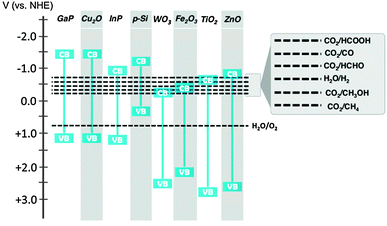 | ||
| Fig. 5 Band gap energies of selected semiconductor materials and redox potentials of water oxidation and CO2 reduction reactions. | ||
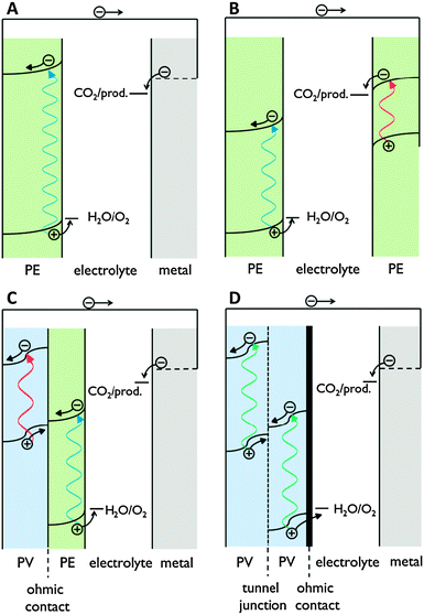
Semiconductors can be used either for creating PV junctions or as photoelectrodes. A photoelectrode is a light-driven electrode that interacts with the electrolyte. Photoanodes and photocathodes perform oxidation or reduction reactions, respectively. Buried PV junctions that are formed by contact of two solid state materials and are completely shielded from the electrolyte are to be distinguished from photoelectrodes.
PEC cells with integrated PV often have been used for solar fuel production. The highest STF efficiencies to date have been achieved by such systems. A drawback of PV based photosystems is the high material cost. A back-of-the-envelope calculation shows that a PEC cell installation producing formic acid with 2% STF efficiency and with a lifetime of 12 years should cost no more than 100 € m−2 to be competitive with fossil fuel.
3. Semiconductor–co-catalyst nano-assemblies
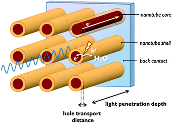
Co-catalysts are added to the semiconductor surface to accelerate and selectivate the half-reactions (eqn (1)–(8)). Co-catalysts in most instances are electrocatalysts, but may be photoactive as well. The semiconductor–co-catalyst combination has to fulfil several functions: (1) light absorption; (2) charge separation and charge carrier transport, and (3) electrocatalysis. Since few single materials score well on every one of these properties, these functions are often distributed over several materials in a multimaterial assembly.In many metal oxides with a small absorption coefficient, a large penetration depth is needed to absorb enough incident light. On the other hand, these materials often suffer from a short hole diffusion length, so charge carriers would be generated too far from the space charge region. To overcome this problem, nanosizing is beneficial and several nanoscale morphologies have been reported.2,12 One-dimensional nanostructures such as nanotubular electrodes orthogonalise photon and hole paths: photons penetrate the nanotubes in the longitudinal direction, while holes generated in the nanotube wall are at nanometre distance from the nanotube surface (Fig. 7). A drawback of nanostructured systems is that they often lack band bending.12 In nanostructured single semiconductors, due to the small dimensions generally no internal electric field can be generated. Charge separation is solely driven by the chemical processes at the semiconductor surface. Water oxidation consumes holes and so drives electrons to the cathode. In this case charge separation is dependent on reaction kinetics.13 The integration of a second semiconductor material generates a heterojunction which drives the separation of electrons and holes because of a difference in band edge energies.13 Interestingly, an electric field in nanosized semiconductor can also be induced by adsorption of a surface layer of charged anions. An electrostatic field generated by a phosphate layer on TiO2 nanocrystals was shown to drive away electrons from the surface and enhance charge carrier lifetime.12
When electron transport is problematic, the material may be doped with electron donors. Besides increasing the electron density of the CB, these also reduce the width of the space charge region.17 Grätzel and co-workers developed host–guest structures in which a material with high electron conductivity serves as a high surface area substrate for an ultrathin layer of photoactive material.17 This approach improves both electron and hole transport. WO3 semiconductor scaffolds can be used and carbon structures are also efficient in extracting electrons from the photoactive material.14 A final and obvious strategy to reduce recombination involves the use of a catalyst that accelerates reaction kinetics and allows shorter charge carrier lifetimes.
The performance of a co-catalyst is commonly expressed using the following parameters:7
Catalyst selectivity (CS). This figure is commonly used to quantify the formation of side products.
 | (9) |
Turnover number (TON). The TON is often reported together with the reaction time. When the TON is reported over the whole lifetime of a catalyst, it is a measure of catalyst stability.
 | (10) |
Turnover frequency (TOF). TOF is a measure of catalytic activity. One must be careful when comparing TOFs, as most catalysts have low stability and initial TOFs can be higher.
 | (11) |
Faradaic efficiency (FE). FE is useful to describe electrochemical selectivity and it is an elegant way to verify the occurrence of side reactions or product cross-over.
 | (12) |
CO2 reduction catalysts can roughly be divided into three groups: (i) all-inorganic metal catalysts, (ii) organic molecules, (iii) metal–organic complexes. Enzymatic conversions, although inspiring, will not be discussed here.2,8
Metal co-catalysts are usually loaded on a semiconductor surface as nanoparticles. They are able to form reaction products beyond two-electron reduction, yielding sometimes even longer alkanes (C2–C9) especially in vapour phase reactions.23,26 The main drawback of metal catalysts is their poor selectivity. A single reaction product is seldom obtained.23 Many metals are also prone to deactivation by poisoning.7,26 Copper, being used for industrial-scale production of methanol from syngas, is an all-time favourite for CO2 reduction studies.26 Besides copper, noble metals (Au, Ag, Pd, Rh, Ru) are effective catalysts, and also Fe, Pb and Ni have been used.7,23 Pt is less suitable for CO2 reduction, as it favours H2 formation.14
All-organic catalysts are metal-free and eliminate the need of expensive transition metals. A breakthrough was achieved recently by Bocarsly and co-workers who reported homogeneous CO2 reduction using pyridinium compounds.27 Pyridine was found to catalyse the 6-electron reduction of CO2 to methanol, with formic acid and formaldehyde as intermediate products. This is remarkable, since pyridine can only transfer one electron at a time. Similar results had been obtained before using tetraalkylammonium salts and aromatic nitriles and esters.27 Organic catalysts generally have high product selectivity and most of them can be operated at low overpotentials.
Metal–organic catalysts are versatile materials since both the metal centre and the organic ligands can be tuned, which results in high selectivities.7 These complexes can adopt multiple redox states and can, in principle, perform multi-electron-transfer reactions. However, in almost all cases CO or formic acid is formed and products beyond 2-electron reductions are not found.21 Distinction can be made between macrocyclic complexes, phosphine complexes and polypyridyl complexes. Macrocyclic complexes can be divided into tetraazamacrocycles, the most popular being Ni(cyclam), and metallomacrocyles, such as porphyrin-like materials. They mostly include Ni, Co or Fe centres.8 Pd is typically used as the metal centre in phosphine compounds.8 The most studied polypyridyl complex is Re(bpy)(CO)3X (bpy = 2,2′-bipyridine and X = Cl or Br). Most of these are based on Re, Ru or Os.7 In general, complexes with bipyridine ligands have better product selectivity and require lower overpotentials. Currently their applicability is limited by low stability and low TOF. These issues have been partially addressed by changing the reaction medium (see Section A.1). Improved performance can also be expected through engineering of the ligands, but a deeper mechanistic understanding will be required for such directed optimization.8
For application in PEC cells, the linkage between the co-catalyst and the semiconductor surface is crucial. Catalyst anchoring can be achieved by direct covalent bonding or as a polymeric film.6,7 Besides improved electronic transport, immobilisation of catalysts leads to enhanced stability and allows the use of materials that are insoluble in the electrolyte phase.7 Covalent attachment is achieved by using ligands with reactive groups, such as carboxylic acid or phosphonic acid (Fig. 8). The nature of these linkers determines the quality of the electronic connection. This aspect has been investigated by Ishitani and co-workers for supramolecular homogeneous complexes.28
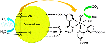 | ||
| Fig. 8 Representation of CO2 reduction using a polypyridyl catalyst anchored to a semiconductor surface. In this scheme, both carboxylic and phosphonic acid linking groups are shown. | ||
For the water oxidation half-reaction commonly noble metal-based oxides such as RuO2 or IrOx were used with good performance.25 Unfortunately, the high cost of these materials may impede their practical application. Through better understanding of water oxidation reaction mechanisms and the functioning of related natural enzymes, catalysts have been developed based on Mn and Co which work at low overpotentials and are less costly.2,12
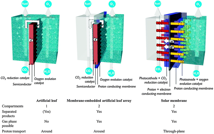
4. Monolithic assembly concepts
The preceding sections have made clear that there is an inextricable link between the development of photosystems and the design of a PEC cell in which the electrode assemblies are operated. Bearing the multitude of requirements in mind, promising concepts from literature are discussed in this section (Fig. 9).The artificial leaf benefits from reduced cost and easy operation. Hydrogen production has been demonstrated by simply depositing an artificial leaf in any recipient filled with water. Even polluted water and sea water have been claimed suitable. Unfortunately, the requirement of a liquid phase reduces CO2 availability. Gaseous products could be kept separated by collecting them on both sides of the planar monolith assembly. Such a separation strategy is successful when employing metre-scale panels.1 However, ionic transport over such macroscopic distances imposes tremendous ohmic losses, as discussed in Section A.1. The trade-off between product separation and proton transport distance restricts the size of an artificial leaf. A computational model has shown that electrode widths of 30 mm already lead to several hundreds of mV overpotential.15
A second approach builds upon the experience with fuel cells and imposes less stringent requirements on the interface and the photoelectrode. In these PEC fuel cells, a membrane–electrode assembly is prepared in a way similar to a fuel cell assembly.23,24,30 In a typical assembly, carbon-based gas diffusion electrodes are coated with semiconductor nanoparticles or, alternatively, a titanium metal sheet is anodized to obtain a porous TiO2 film. A counter electrode is operated in the dark and typically consists of metal nanoparticles deposited on a carbon substrate. These components are hot-pressed to obtain a monolithic membrane–electrode assembly and inserted in a two-compartment reactor. In 1996, Ichikawa and Doi produced methane in a PEC fuel cell using TiO2 thin film as the photoanode and a ZnO/Cu co-catalyst as the cathode.30 Centi and co-workers reported formation of long-chain alkanes by operating the cathode compartment in the gas phase.23 They employed Fe co-catalyst on carbon nanotube supports in combination with a TiO2 nanotube photoanode fabricated by anodisation. In these PEC fuel cells only one side is illuminated, which allows non-transparent electrode materials to be used. Electrical connection is achieved by an external wire, so common proton exchange membranes may serve for the interface. However, reported efficiencies are still quite low. Product evacuation and proton transport are suboptimal in the current embodiment.24 Current PEC fuel cells contain a single photosystem. Performance is expected to improve by integration of multiple small band gap semiconductors, which will drive charge separation and enhance visible light absorption.
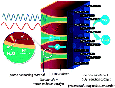
In contrast to the artificial leaf, in a solar membrane, the efficiency will not decrease when the PEC cell surface area is increased. The porous electrodes allow short proton conduction pathways, which is important for operation at mild pH, or in vapour phase. The solar membrane concept offers assemblies with good light harvesting capabilities and the possibility to fine tune each side individually. At the same time, the membrane is a weakness of these devices. Besides the high cost, a proton exchange membrane is sensitive to poisoning by alkali and alkaline earth cations present in most water sources. When operated using water in the vapour phase, this problem is largely avoided. Care must be taken to avoid dehydration of the membrane, however, because proton conductivity is critically dependent on hydration. Clearly, there is a strong need for research on these multifunctional interfaces.
Even though promising concepts have already been demonstrated, none of the current PEC cells fulfil all four requirements for practical application: (i) high STF efficiency, (ii) low cost, (iii) high durability and (iv) suitability for scale-up. While research focus in the past was mostly on the first three conditions, suitability for scale-up should also be considered early on in the design of assemblies and PEC cells. This implies that on an industrial scale, the synthesis techniques should be accessible at a reasonable cost and the reaction products should be safely collected. The cost of industrial-scale solar fuel plants has already been addressed by Pinaud et al.1 Through a cost analysis, it has been suggested that integrated PEC devices could possibly produce hydrogen at a lower cost than a PV-coupled electrolyzer system.1 Finally, since the purpose of solar fuel research is to provide a sustainable alternative to fossil fuels, the environmental impact of PEC cell production and operation is an essential factor when evaluating different approaches. This was studied by Zhai et al. using life cycle assessment.31
B. Emerging tools for artificial photosynthesis
1. PEC cell component synthesis techniques
PEC cells are built for optimal transport of light, molecules, protons and electrons. As such, composite multimaterials have to be brought together in a compatible assembly with careful attention for all functions. The synthesis method determines to a large extent the quality and performance of an electrode assembly. Such a multifunctional system puts strong demands on the precision of the technique, yet the targeted broad application of solar fuel production prescribes low-cost manufacturing. The ideal technique allows for large-scale production yet nanoscale control over the final assembly. Instead of attempting an exhaustive overview of electrode synthesis techniques, here a selection of techniques is discussed that meets these requirements.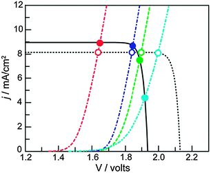 | ||
| Fig. 10 J–V curves of a triple junction Si PV (solid black line) idealized PV (dashed black line), and different water oxidation catalysts (colored lines). The intersections indicate the working point of the assemblies. Catalysts with lower activity (light blue curve) are more strongly affected by the potential difference that can be generated by the PV (compare empty and filled light blue circles). Reproduced with permission from ref. 32. Copyright 2012, National Academy of Sciences. | ||
Since dense silicon wafers impede proton transport in a PEC cell, silicon microwires are under investigation that allow through-plane transport16 (Fig. 7). Such microwires also increase surface area and provide short charge carrier paths, similar to nanotubular structures. As a consequence, less pure and less costly silicon can be used.12 Microstructured silicon photoelectrodes can be put in contact with the electrolyte to generate a semiconductor–liquid junction. To further increase charge carrier separation, an internal radial junction can be introduced.16 A great benefit of silicon microwires, when embedded in a polymer membrane, is the flexibility. The introduction of microwires on both sides potentially affords a flexible electrode assembly with high efficiency. Silicon microwires have been tested as a photocathode but are less suitable as a photoanode. Metal oxides of similar morphology could take up this role. Alternatively, silicon photoanodes can be fabricated that are stabilised by a protective charge tunnelling layer.
The inverse morphology of silicon wires, i.e. porous silicon (porSi) was developed in the early '90s.33 PorSi can be obtained by electrochemical etching of silicon in HF,33 or by a simple electroless etching procedure in HF–H2O2 solution, catalysed by metal particles.34 Combined with nanopatterning of surfaces by means of nanosphere self-assembly, the latter offers new possibilities to create ordered pores with controllable size.34 PorSi is a highly tunable material. Pore morphology ranges from unidirectional pores to dendritic structures or even nanopillars at very high porosities. The material is applied in PV cells as an antireflection coating, and devices using porSi as the sole light absorber have been reported.35 The application of porSi membranes in fuel cells is of particular interest for PEC cells. A silicon-based inorganic–organic membrane was fabricated with higher proton conductivity than Nafion®, no volumetric size change, and when used in a fuel cell at low humidity, it produces a power density that is an order of magnitude higher than other systems.36 These advantages were obtained by creating pores with diameters of 5–7 nm, adding a self-assembled molecular monolayer on the pore surface, and capping the pores with a layer of porous silica. The limited sensitivity to low humidity is an interesting feature for PEC cells operating in the vapour phase and at ambient temperature. If porSi would be used in a PEC cell, the functions of photoelectrode and membrane would be combined in a single material, seriously reducing PEC cell cost. The band gap of porSi is widened compared with dense Si, and dependent on porosity.33 This allows tuning of the band gap for optimal solar absorption and band edge positions for the requested reactions. If a porosity gradient is applied to the structure, it is speculated that the resulting internal electric field could enhance charge separation. After etching, electronic conductivity of porSi is decreased, caused by the discontinuous morphology. Free charge carrier populations can be influenced however, by interaction with adsorbed species on the large internal surface area of porSi (up to 600 m2 cm−3). The adsorption of NO2 or NH3 can turn porSi into a p-type or n-type semiconductor, respectively.37 Overall, porSi is a small band gap, high surface area material that reduces PEC cell cost by using less Si of lower purity and by replacing the membrane component. Although it has not been investigated in PEC cells until now, recent developments encourage the introduction of this versatile material.
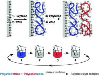
Fig. 11 shows the deposition of LbL films by dipping, but methods such as spray-assisted39 or spin-assisted LbL assembly or inkjet printing40 have been successfully employed as well and scaled-up roll-to-roll processes are already used in industrial production enabling the coating of millions of m2 per year. Consequently LbL assembly has spread into a large number of different areas of applications (PV, optoelectronic devices, energy storage, coatings, microreactors, flexible electronics, tissue engineering, biosensors, (bio)catalysis,…) over the last years and led to substantial or even groundbreaking advances in many cases.
LbL has not yet been applied in PEC cell research but was found useful in related fields, including photocatalysis, fuel cells and PV.38 The composite nature of PEC cells makes LbL assembly an excellent method for the fabrication of cells. We believe that multi-component LbL films could find their merits in PEC cells with respect to electrode construction, band gap engineering, dye sensitisation and light harvesting, barrier properties, electrical and proton conduction, corrosion prevention, pore design or catalyst layers. LbL films have already been used in the past as examples for all of these functions so the door to finding the right components and film deposition conditions for matching PEC cell requirements is, in our opinion, wide open.
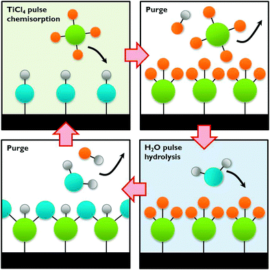 | ||
| Fig. 12 The ALD process exemplified by TiCl4 chemisorption on a hydroxylated surface followed by hydrolysis. | ||
A wide choice of materials is accessible with ALD, many of which bear promise as a photoanode or photocathode in a PEC cell, especially when deposited on a nanostructured substrate such as carbon or silicon nanomaterials. Even composite thin films can be synthesised by the sequential deposition of different precursors, in order to increase charge separation and light absorption. Such nanoscale heterojunctions show great potential if the composite layer size can be precisely tuned.12,13 ALD can be combined with in situ doping to manipulate band gap energetics and enhance conductivity. Co-catalysts such as transition metals, metal oxides and even alloys can be deposited with tuneable sizes. All these possibilities make this technique ideally suited for PEC cell development. As discussed in Section A.3 some photoelectrodes are prone to corrosion. ALD may offer a way to protect the electrodes by applying a protective thin film. This protective layer shields the material from the electrolyte and passivates surface states. ALD has been successfully used by Grätzel and co-workers for protecting an unstable p-Cu2O photocathode with several nanolaminate ZnO/Al2O3/TiO2 layers.12 This approach is also applicable to co-catalysts and could in general increase the PEC cell performance and lifetime.42
So far ALD has been used mainly in microelectronics for the deposition of highly insulating layers of only a few nm onto small surfaces. As the scale of ALD is only limited by the size of the reaction chamber, large scale production of photoelectrodes for PEC cells seems feasible. When producing multimaterial films with layers of several hundredths of nm on larger substrates, the slow film growth (typically 0.1 nm s−1) could be impractical. To overcome this limitation alternatives such as spatial ALD have been investigated.43 Spatial ALD (Fig. 13) can even be applied in roll-to-roll printing. The sequential and self-limiting nature of ALD is perfectly compatible with LbL. One could imagine a roll-to-roll printing process in which LbL deposition steps are alternated with ALD treatments.
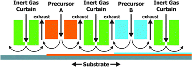 | ||
| Fig. 13 Schematic example of spatial ALD with separation of different precursor reactions by an inert gas curtain. Horizontal movement of the substrate leads to the sequential deposition of monolayers. Reproduced with permission from ref. 43. Copyright 2012, American Vacuum Society. | ||
2. Elaboration of future PEC cell designs
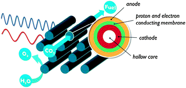
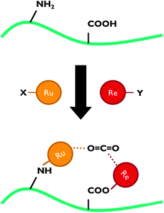
The ALD, LbL and porSi material tools could be used to create a next generation of monolithic assemblies. In this section we describe two innovative approaches to illustrate where future research could lead.A layered polymeric structure is ideally assembled via the LbL technique. LbL allows tuning the thickness of e.g. the proton conducting membrane for optimal gas separation yet minimal proton transport resistance. The anode and cathode thicknesses are chosen according to their light absorption and charge transport properties. An electrically conducting polymer could be the ideal backbone to immobilise CO2 reduction catalysts. By using a monomer with different functional groups, it is possible to precisely immobilise two or more catalytic complexes relative to each other (Fig. 16). Instead of a single catalytic centre, catalytic pockets can then be created in an ‘artificial enzyme’. It has been shown that such simultaneous interaction with multiple catalytic species can be an effective strategy to activate the CO2 molecule.28
3. PEC characterisation methods
With PEC development still in its infancy, there is a lack of in situ characterisation methods. Conventional techniques often focus on individual cell components and consider only one of the half-reactions. For a deeper understanding, PEC cells should be monitored in real-time so both steady-state and transient effects can be investigated.Such investigations have been carried out by some of the present authors for (two-electrode) PEC cell chronoamperometry (Fig. 17).24 In PEC cell chronoamperometry, the current is recorded as a function of time at a certain potential. Most measurements are performed at short circuit (0 V), but a bias may be applied. By shutting the illumination on and off, both transient effects and steady-state photocurrents can be investigated. The contributions of PEC cell components can be deconvoluted from the photocurrent profiles by modulating the reaction conditions or light source and comparing the response. For example, the addition of hydrogen peroxide as a hole scavenger will facilitate the anodic reaction and rule out any problems associated with the oxidation half-reaction. By introducing acid, the influence of proton transport on performance is largely eliminated. Importantly, overall PEC cell efficiencies are only realistic when obtained in a two-electrode set-up at short circuit, to avoid extracting additional power from the instrument. Chemical bias in two-compartment PEC cells can be avoided by keeping the pH of both sides identical. When using monochromatic light, the photon flux is known and the incident-photon-to-current-efficiency (IPCE or external quantum efficiency (EQE)) can be estimated:44
 | (13) |
The STF efficiency is obtained when using simulated solar light (typically Air Mass 1.5) at 1 sun intensity (100 mW cm−2), or under concentrated solar illumination.44 In addition, claims on STF efficiency should be based on quantification of formation rates of solar fuel and molecular oxygen. Provided the Faradaic Efficiency (FE) is known, STF efficiency can be calculated from the photocurrent:
 | (14) |
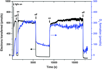 | ||
| Fig. 17 Monitoring of photocurrent and D2 formation out of deuterated water in a fuel cell type solar membrane PEC cell with interrupted illumination. Reproduced from ref. 24 with permission from the PCCP owner societies. | ||
Virtually any electrochemical characterisation method could be applicable to PEC cells and Electrochemical Impedance Spectroscopy (EIS) is especially useful. EIS has multiple uses for in situ PEC cell research. It makes use of a small modulated voltage perturbation at different frequencies. The response of the PEC cell can be modelled as an equivalent circuit containing resistive (e.g. charge transport) and capacitive (e.g. semiconductor space charge layer) elements with different time constants. From the constructed model, information can be gathered about various processes including charge trapping, surface recombination and reaction kinetics.17 Besides the properties of only one photoelectrode, overall PEC cell characteristics can be obtained in a two-electrode measurement. Information could be gathered about electrolyte and membrane transport resistance, and kinetic processes at the second electrode.45
Product detection is a direct way to measure PEC cell performance. If the electrical current is compared with production rates, product selectivity and Faradaic efficiency can be calculated, which are necessary to calculate STF efficiency.44 Since PEC cell photocurrents are seldom constant, Faradaic efficiency is likely to be time-dependent as well.24 Real-time product detection is required to determine whether features in photocurrent transients are associated with product formation or other, non-Faradaic processes. Moreover, in wireless PEC cells no current can be measured so product formation rate is the primary metric to characterise these systems.6,20
Mechanistic information can be obtained by modulating the illumination source and reagents. For example, catalytic activity can be investigated by cyclic voltammetry coupled to mass spectrometry, under CO2 or under Ar atmosphere and in the dark or under illumination.8 Isotope tracer experiments (using 13CO2, D2O or H218O) confirm the atom source and may exclude photocorrosion or reaction with impurities.6,24
Transient Absorption Spectroscopy (TAS), also referred to as pump–probe spectroscopy or flash photolysis, relies on the instantaneous excitation of a system by an extremely short laser pulse (pump), followed by absorption spectroscopy using a second light source (probe). The probe can be a continuous illumination source or a time-delayed laser pulse, if events are to be studied on (sub-)nanosecond time scales. The decay of the excited species can be followed by the changes in absorption compared to the ground state of the system. By probing this absorption at various times after the pump pulse, a two-dimensional map is obtained as a function of wavelength and time. This time-resolved technique allows observation of species that are very short-lived. It has been used to look at charge carrier dynamics, reaction kinetics and catalytic cycles.12,13 TAS gives direct information about hole dynamics, in contrast with electrochemical techniques which are based on the extraction of electrons from the photoelectrode. Tang et al. observed free and trapped hole populations in TiO2, and provided proof for a 4-hole water oxidation reaction.46 Sakai and co-workers used TAS to investigate charge transfer within supramolecular complexes for CO2 reduction.28 While TAS on powder samples and homogeneous catalysts provides important insights, in situ measurements are needed that reliably reproduce the operating conditions of a PEC cell. Cowan et al. built a complete three-electrode PEC cell for TAS studies of nanocrystalline TiO2 photoelectrodes.47 They found that although slow water oxidation kinetics cause charge carrier recombination, the application of a positive bias leads to the removal of electrons and enhances the lifetime of photogenerated holes, which are then successfully used to oxidise water. In their system, separate electrodes were used on a transparent conducting glass substrate. Most monolithic PEC cells will be non-transparent, and will have to be used in a reflection set-up rather than in transmission mode. The combination of light excitation, electrochemical control and direct observation of charge carriers and intermediates makes in situ TAS an ideal technique for both fundamental studies and performance characterisation of PEC cells.
Models for hydrogen producing PEC cells have been developed, but so far models for the photoelectrochemical reduction of CO2 are not available. Until recently, models for hydrogen producing PEC cells were mostly based on equivalent circuit models, introduced by Rocheleau and Miller.50 These represent the PEC cell as an electrical circuit with an electrochemical load to account for ohmic losses and kinetic overpotentials. This theoretical approach has been widely used to model separate components of a PEC cell, e.g. to estimate photopotential as a function of semiconductor band gap in order to predict ideal light absorber materials or co-catalysts.45 These models, however, are not detailed enough to grasp all features of a practical PEC cell. Multidimensional and multiphysics numerical modelling that includes charge and species conservation, accounts for electrochemical reaction kinetics and incorporates electron and ion transport phenomena are needed. An accurate model should allow identification of rate-limiting steps and indicate the improvements that can be expected with alternative materials, whether existing or hypothetical. Models incorporating spatial variables are useful to develop optimal reactor geometries.
Model-based device engineering is receiving more attention. Haussener et al. developed an adequate model based on mass and charge conservation, a Nernst–Planck description of species transport and Butler–Volmer equations for describing electrochemical kinetics.15 This way they were able to simulate and compare different PEC cell geometries. They showed improved photocurrent densities by reduced ohmic losses when a transparent conducting oxide was added for current collection. Cross-over between compartments was calculated to be highest when the system was continuously flushed.
Conclusions
The development of monolithic cells for solar fuel production is a lively research field, and solar hydrogen currently is the most popular topic. Progress is being made on the grand scientific challenge of CO2 reduction catalysts to produce solar carbon fuel, but the design of monolithic assemblies and PEC cells dedicated to CO2 reduction is still in its infancy. PEC cell design is a complex matter and involves simultaneous managing of a multitude of processes related to illumination, charge separation, electrical conduction, molecular transport, catalytic chemistry, feed supply and reaction product recovery. This review has shown that these aspects should be an integral part of research on solar fuels. Promising concepts are the artificial leaf and the solar membrane. The sophistication of their design by implementing porosity and adopting concentric layered multimaterial assemblies will initiate a gradual transition from planar designs to truly three-dimensional structures. Atomic layer deposition and layer-by-layer assembly are enabling technologies to build future assemblies. The guidance by in situ time and space resolved spectroscopies and advanced modelling will path the way forward. The strategies discussed in this review are expected to lift the limited carbon-based solar-to-fuel efficiency closer to the levels of current solar hydrogen producing cells.Acknowledgements
JR acknowledges the Research Foundation – Flanders (FWO) for a PhD grant. JAM is beneficiary of long-term structural funding (Methusalem) by the Flemish government. JR, TB, FT and JAM participate in an interuniversity IAP-PAI programme supported by the Belgian government. The authors thank Mikael Dumortier and Sophia Haussener for helpful discussions.Notes and references
- B. A. Pinaud, J. D. Benck, L. C. Seitz, A. J. Forman, Z. Chen, T. G. Deutsch, B. D. James, K. N. Baum, G. N. Baum, S. Ardo, H. Wang, E. L. Miller and T. F. Jaramillo, Energy Environ. Sci., 2013, 6, 1983–2002 CAS and references therein.
- K. S. Joya, Y. F. Joya, K. Ocakoglu and R. van de Krol, Angew. Chem., Int. Ed., 2013, 52, 10426–10437 CrossRef CAS PubMed and references therein.
- A. Fujishima and K. Honda, Nature, 1972, 238, 37–38 CrossRef CAS.
- J. Hemminger, R. Carr and G. Somorjai, Chem. Phys. Lett., 1978, 57, 100–104 CrossRef CAS.
- M. Halmann, Nature, 1978, 275, 115–116 CrossRef CAS.
- T. Arai, S. Sato, T. Kajino and T. Morikawa, Energy Environ. Sci., 2013, 6, 1274–1282 CAS and references therein.
- B. Kumar, M. Llorente, J. Froehlich, T. Dang, A. Sathrum and C. P. Kubiak, Annu. Rev. Phys. Chem., 2012, 63, 541–569 CrossRef CAS PubMed and references therein.
- E. E. Benson, C. P. Kubiak, A. J. Sathrum and J. M. Smieja, Chem. Soc. Rev., 2009, 38, 89–99 RSC and references therein.
- E. V. Kondratenko, G. Mul, J. Baltrusaitis, G. O. Larrazábal and J. Pérez-Ramírez, Energy Environ. Sci., 2013, 6, 3112–3135 CAS and references therein.
- M. Mikkelsen, M. Jørgensen and F. C. Krebs, Energy Environ. Sci., 2010, 3, 43–81 CAS.
- M. Romero and A. Steinfeld, Energy Environ. Sci., 2012, 5, 9234–9245 CAS.
- F. E. Osterloh, Chem. Soc. Rev., 2013, 42, 2294–2320 RSC and references therein.
- A. J. Cowan and J. R. Durrant, Chem. Soc. Rev., 2012, 42, 2281–2293 RSC and references therein.
- W. Fan, Q. Zhang and Y. Wang, Phys. Chem. Chem. Phys., 2013, 15, 2632–2649 RSC.
- S. Haussener, C. Xiang, J. M. Spurgeon, S. Ardo, N. S. Lewis and A. Z. Weber, Energy Environ. Sci., 2012, 5, 9922–9935 CAS and references therein.
- J. M. Spurgeon, M. G. Walter, J. Zhou, P. a. Kohl and N. S. Lewis, Energy Environ. Sci., 2011, 4, 1772–1780 CAS.
- R. Van de Krol and M. Grätzel, Photoelectrochemical hydrogen production, Springer, 2012 and references therein Search PubMed.
- K. Maeda, M. Higashi, D. Lu, R. Abe and K. Domen, J. Am. Chem. Soc., 2010, 132, 5858–5868 CrossRef CAS PubMed.
- J. Newman, J. Electrochem. Soc., 2013, 160, 309–311 CrossRef PubMed.
- S. Reece, J. Hamel, K. Sung, T. Jarvi, A. J. Esswein, J. J. H. Pijpers and D. G. Nocera, Science, 2011, 334, 645–648 CrossRef CAS PubMed and references therein.
- D. C. Grills and E. Fujita, J. Phys. Chem. Lett., 2010, 1, 2709–2718 CrossRef CAS and references therein.
- P. Voyame and K. Toghill, Inorg. Chem., 2013, 52, 10949–10957 CrossRef CAS PubMed.
- C. Ampelli, G. Centi, R. Passalacqua and S. Perathoner, Energy Environ. Sci., 2010, 3, 292–301 CAS.
- J. Rongé, D. Nijs, S. Kerkhofs, K. Masschaele and J. Martens, Phys. Chem. Chem. Phys., 2013, 15, 9315–9325 RSC.
- M. G. Walter, E. L. Warren, J. R. McKone, S. W. Boettcher, Q. Mi, E. a. Santori and N. S. Lewis, Chem. Rev., 2010, 110, 6446–6473 CrossRef CAS PubMed and references therein.
- S. Roy, O. Varghese, M. Paulose and C. Grimes, ACS Nano, 2010, 4, 1259–1278 CrossRef CAS PubMed.
- Y. Oh and X. Hu, Chem. Soc. Rev., 2013, 42, 2253–2261 RSC.
- M. Schulz, M. Karnahl, M. Schwalbe and J. G. Vos, Coord. Chem. Rev., 2012, 256, 1682–1705 CrossRef CAS PubMed and references therein.
- R. E. Rocheleau, E. L. Miller and A. Misra, Energy Fuels, 1998, 12, 3–10 CrossRef CAS.
- S. Ichikawa and R. Doi, Catal. Today, 1996, 27, 271–277 CrossRef CAS.
- P. Zhai, S. Haussener and J. Ager, Energy Environ. Sci., 2013, 6, 2380–2389 CAS.
- Y. Surendranath, D. K. Bediako and D. G. Nocera, Proc. Natl. Acad. Sci. U. S. A., 2012, 109, 15617–15621 CrossRef CAS PubMed.
- P. Menna, G. Di Francia and V. La Ferrara, Sol. Energy Mater. Sol. Cells, 1995, 37, 13–24 CrossRef CAS.
- L. Boarino, E. Enrico, N. De Leo, F. Celegato, P. Tiberto, K. Sparnacci and M. Laus, Phys. Status Solidi A, 2011, 208, 1403–1406 CrossRef CAS.
- M. Ernst and R. Brendel, Phys. Status Solidi, 2012, 6, 187–189 CAS.
- S. Moghaddam and E. Pengwang, Nat. Nanotechnol., 2010, 5, 230–236 CrossRef CAS PubMed.
- E. Garrone, F. Geobaldo, P. Rivolo, G. Amato, L. Boarino, M. Chiesa, E. Giamello, R. Gobetto, P. Ugliengo and A. Viale, Adv. Mater., 2005, 17, 528–531 CrossRef CAS.
- E. Seyrek and G. Decher, in Polymer Science: A Comprehensive Reference, ed. K. Matyjaszewski and M. Möller, Elsevier, 2012, pp. 159–185 and references therein Search PubMed.
- A. Izquierdo, S. S. Ono, J.-C. Voegel, P. Schaaf and G. Decher, Langmuir, 2005, 21, 7558–7567 CrossRef CAS PubMed.
- J. Hiller, J. D. Mendelsohn and M. F. Rubner, Nat. Mater., 2002, 1, 59–63 CrossRef CAS PubMed.
- C. Detavernier, J. Dendooven, S. P. Sree, K. F. Ludwig and J. A. Martens, Chem. Soc. Rev., 2011, 40, 5242–5253 RSC.
- Q. Peng, J. S. Lewis, P. G. Hoertz, J. T. Glass and G. N. Parsons, J. Vac. Sci. Technol., A, 2012, 30, 010803 Search PubMed.
- P. Poodt, D. C. Cameron, E. Dickey, S. M. George, V. Kuznetsov, G. N. Parsons, F. Roozeboom, G. Sundaram and A. Vermeer, J. Vac. Sci. Technol., A, 2012, 30, 010802 Search PubMed.
- Z. Chen, T. F. Jaramillo, T. G. Deutsch, A. Kleiman-Shwarsctein, A. J. Forman, N. Gaillard, R. Garland, K. Takanabe, C. Heske, M. Sunkara, E. W. McFarland, K. Domen, E. L. Miller, J. A. Turner and H. N. Dinh, J. Mater. Res., 2011, 25, 3–16 CrossRef.
- T. Lopes, L. Andrade, H. A. Ribeiro and A. Mendes, Int. J. Hydrogen Energy, 2010, 35, 11601–11608 CrossRef CAS PubMed.
- J. Tang, J. R. Durrant and D. R. Klug, J. Am. Chem. Soc., 2008, 130, 13885–13891 CrossRef CAS PubMed.
- A. J. Cowan, J. Tang, W. Leng, J. R. Durrant and D. R. Klug, J. Phys. Chem. C, 2010, 114, 4208–4214 CAS.
- U. Scheler, Curr. Opin. Colloid Interface Sci., 2009, 14, 212–215 CrossRef CAS PubMed.
- R. Bhattacharyya, B. Key, H. Chen, A. S. Best, A. F. Hollenkamp and C. P. Grey, Nat. Mater., 2010, 9, 504–510 CrossRef CAS PubMed.
- R. E. Rocheleau and E. L. Miller, Int. J. Hydrogen Energy, 1997, 22, 771–782 CrossRef CAS.
Footnote |
| † Electronic supplementary information (ESI) available: Additional details on record STF efficiencies of Fig. 1, slideshow. See DOI: 10.1039/c3cs60424a |
| This journal is © The Royal Society of Chemistry 2014 |


