 Open Access Article
Creative Commons Attribution 3.0 Unported Licence
Double bubbles: a new structural motif for enhanced electron–hole separation in solids
A. A.
Sokol
a,
M. R.
Farrow
a,
J.
Buckeridge
a,
A. J.
Logsdail
a,
C. R. A.
Catlow
a,
D. O.
Scanlon
ab and
S. M.
Woodley
*a
aDepartment of Chemistry, Kathleen Lonsdale Materials Chemistry, University College London, 20 Gordon Street, London WC1H 0AJ, UK. E-mail: a.sokol@ucl.ac.uk; m.farrow@ucl.ac.uk; j.buckeridge@ucl.ac.uk; scott.woodley@ucl.ac.uk
bDiamond Light Source Ltd., Diamond House, Harwell Science and Innovation Campus, Didcot, Oxfordshire OX11 0DE, UK
First published on 18th June 2014
Abstract
Electron–hole separation for novel composite systems comprised of secondary building units formed from different compounds is investigated with the aim of finding suitable materials for photocatalysis. Pure and mixed SOD and LTA superlattices of (ZnO)12 and (GaN)12, single-shell bubbles are constructed as well as core@shell single component frameworks composed of larger (ZnO)48 and (GaN)48 bubbles with each containing one smaller bubble. Enthalpies of formation for all systems are comparable with fullerenes. Hole and electron separation is achieved most efficiently by the edge sharing framework composed of (GaN)12@(ZnO)48 double bubbles, with the hole localised on the nitrogen within the smaller bubbles and the excited electron on zinc within the larger cages.
1. Introduction
Semiconducting materials that upon photoexcitation in the UV/blue-visible part of the spectrum produce readily separable electron–hole pairs are desirable for a number of applications. For example, optoelectronic devices such as blue light emitting diodes (LEDs) and lasers have only recently become available due to the limitations of the current generation of semiconductor heterostructures.1 Furthermore, one of the grand challenges in contemporary materials science is the one-step splitting of water into hydrogen and oxygen using a single heterogeneous photocatalyst,2 which involves the separation of electron–hole pairs. Traditionally, oxide materials have been used in this application.3 In recent years oxynitrides have emerged as promising alternatives, often possessing smaller band gaps than oxides, whilst retaining the excellent stability to aqueous environments.4 One of the most promising oxynitrides of the past decade has been a solid solution between GaN and ZnO,5 which crystallises in the wurtzite structure and was shown to be able to achieve water splitting into H2 and O2 under visible light irradiation. To enhance the efficiency of the GaN:ZnO system for water splitting, it is also imperative to avoid the recombination of the photo-generated electron–hole pair. Progress in the manufacture of GaN and GaN:ZnO p–n junctions has led to fundamental and technological breakthroughs.6–8 An important step was the discovery of unique properties of these materials as nanoparticles.9In this article, we propose a novel structural motif that will spatially separate electrons and holes in GaN:ZnO systems, employing a “bottom-up” approach based on preceding global optimisation studies of nanoscale systems. Previous computational simulations10–12 have predicted that both ZnO and GaN, at nanoscale and sub-nanoscale, form clusters with a cage, or “bubble” architecture that are dramatically different from models based on cuts from the wurtzite bulk structure. Using ZnO and SiC as two simple examples, we have also shown how individual bubbles can combine to form extended framework materials;13,14 alternative constructions and the viability (or stability) of similar frameworks from building blocks of bubbles has additionally been reported.10,13–15
Enhanced stability is typically correlated with an increase in the density of framework materials, which can be achieved by selecting appropriate building units. In our approach to framework construction, we use so-called double bubbles. These double bubbles are denser and are a preferred motif for larger sized clusters. We have recently demonstrated16 the viability of this approach by constructing one such framework with a double bubble formed of 120 atoms. In that work we found that the standard enthalpy of formation for the edge-sharing (GaN)12@(ZnO)48 double bubble is 13 kJ mol−1, which is comparable to the typical range of thermodynamic stability of fullerenes.17,18
Experimentally observed cage structures have been reported for boron nitride (BN),19,20 cadmium selenide (CdSe),21,22 and molybdenum sulphide (MoS2).23–25 Furthermore, layered core–shell nanoparticles and their composites have been designed previously for quantum dots for a similar purpose of electron–hole separation, e.g. ZnS and CdSe.26,27
In this paper, we investigate the different configurations of single- and double-bubble systems, and, importantly, how these affect the electronic structure of both the individual double-bubble clusters and the constructed frameworks. Details of how the frameworks are constructed are given below, whereas we refer the reader to ref. 16 for analysis of the relaxed atomic structures for the double bubble of pure ZnO, pure GaN and the combinations of these two.
2. Method
2.1 Construction of double bubble clusters
We consider the binary (ZnO and GaN) tetrahedral compounds that are predicted to have stable and metastable nanosized bubble structures. These structures are composed of only three-coordinated atoms, sets of which create rings with an even number of sides. The higher-symmetry configurations of the bubbles are typically found to be more stable. As high-symmetry cluster structures are only possible for certain sizes, they are not only the stable state for their particular size, but usually have a greater stability than clusters of neighbouring sizes. In our previous studies10,13,14 we have, therefore, focused our attention on families of high symmetry structures, and, in particular, those with symmetry Th, Td and T.A double bubble is formed by inserting the smaller bubble inside the larger (see Fig. 1), aligned with the same centre of mass and identical direction of orthogonal axes, with each axis passing through the centre of mass and the centre of opposite truncated corners, or tetragonal faces. The rotation angle of the opposite faces about the octahedral axes with respect to each other is dependent upon the symmetry of the cluster. In clusters of Th or Td symmetry, this angle is 45°, whereas for T symmetry, the rotation angle is between 0° and 45°. Based on stability, the best match is obtained when the inner and outer bubbles are taken from the set of Th bubbles, and the highest density is achieved by combining the smallest two of these clusters: n = 12 (a sodalite cage) and n = 48.
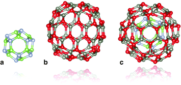 | ||
| Fig. 1 Double bubble cluster creation: a sodalite cage with n = 12, (a), is placed inside an n = 48 cage, (b), to form the double bubble, (c), with hexagonal rings of inner and outer bubbles aligned. Colour: green is reserved for Ga, steel blue for N, red for O, and slate grey for Zn. Graphics were generated using the VESTA package.28 | ||
If the distance between a hexagonal ring of the inner bubble and the parallel hexagonal face in the outer bubble falls in the range of a typical bond length, then we shall refer to this as an ideal match; whether there is an ideal match depends on the composition. Upon relaxation, we may expect minimal buckling and therefore expect the double bubble will maintain Th symmetry. For a mismatch, typically the outer bubble buckles and only a fraction of the possible 8 × 6 bonds is formed.
For each composition of double bubbles, both Th and T starting configurations as well as a number of structures with lower-order point groups were constructed, and then geometry optimised with and without symmetry constraints. The systems we have studied in this way are: mixed core@shell double bubble clusters, (GaN)12@(ZnO)48 and (ZnO)12@(GaN)48; and the corresponding pure systems, (ZnO)12@(ZnO)48 and (GaN)12@(GaN)48.
2.2 Construction of extended frameworks
Previous work has already shown the feasibility of frameworks constructed from high-symmetry bubbles as secondary building units (SBU).10,13–15,29–34 In fact, the reverse process of decomposing microporous frameworks into component cages is used by the zeolite community. The n = 12 bubble with symmetry Th is the basic cage of the mineral sodalite and one of the key component cages in many other frameworks, including, FAU, LTA and EMT zeolites.35 The synthesis of microporous frameworks usually involves an organic molecule, which helps to steer the nucleation towards the formation of cages. Such template molecules could either be left within cages or removed using post-synthetic treatments.As the high-symmetry bubble structures (described in the previous section) are stable, we now investigate three possible frameworks that can be constructed from these. Our choice of frameworks is based on: (a) the relative stability of frameworks previously constructed from only (ZnO)n bubbles, (b) the need to keep the number of atoms within the unit cell to a manageable number, which would be amenable to DFT investigations, and (c) the extra flexibility of having cages of two compounds.
For all frameworks, we impose the constraint that: each concentric layer of the double bubble SBU cage is composed of only one binary compound; 1![[thin space (1/6-em)]](https://www.rsc.org/images/entities/char_2009.gif) :
:![[thin space (1/6-em)]](https://www.rsc.org/images/entities/char_2009.gif) 1 ratio of SBU for superlattices composed of both ZnO and GaN SBU; and the SBU do not overlap, i.e. the secondary building units are, using terminology defined in ref. 36, bonded rather than merged so that the frameworks can be formed from a bath of SBU.
1 ratio of SBU for superlattices composed of both ZnO and GaN SBU; and the SBU do not overlap, i.e. the secondary building units are, using terminology defined in ref. 36, bonded rather than merged so that the frameworks can be formed from a bath of SBU.
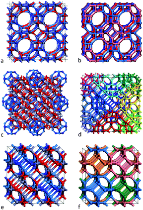
The first framework is constructed from single-shell bubbles – sodalite cages of (ZnO)12 and (GaN)12. As the typical Zn–O and Ga–N bond lengths are similar (1.98 Å and 1.95 Å in the ground state wurtzite form of these materials), their respective sodalite cages are also similar in size. Consider each SBU as an octahedron; we construct an fcc lattice by corner-sharing SBU, see Fig. 2(a) and (b). Note that if the tetragonal rings of the sodalite cages were merged then the voids between these cages would also take shape of a sodalite cage. However, the SBU are actually spaced apart by one bond length so that at each corner we have created an n = 4 cuboid (a double ring) and larger voids between the SBU in the form of n = 24 bubbles, which are formed of six octagons, eight hexagons and eight tetragons. Note the symmetry of these SBU is reduced from Oh to T, as they are composed of both ZnO and GaN. The resulting extended system is analogous to the zeolitic framework known (and will be referred to here) as LTA.
The second framework is constructed from the n = 60 double bubbles described in the section above; see Fig. 1(c) and 2(c). Rather than corner-sharing, the SBU are now stacked in an edge-sharing pattern; each double bubble is surrounded by twelve others (see Fig. 2(d)), and each edge of the outer bubble is one bond length from an edge of a neighbouring bubble, forming an n = 6 double ring (also called a drum) and two n = 2 rings. Each tetragonal ring of an outer n = 48 bubble combines with five others to form an n = 12 bubble with Th symmetry, so the void takes form of a sodalite cage. The inner sodalite cage of each double bubble is formed from (i) the same compound or (ii) two compounds, which we alternate.
The third, and final, framework is in fact the sodalite framework (referred to as SOD) and is composed of the n = 12 single sodalite bubbles (as used in the first framework). This framework can be constructed by merging, rather than bonding, the SBU whilst following the procedure described for the first framework. In order to obey the constraint of wanting bonded rather than merged SBU, however, we construct this framework by edge-sharing the SBU – this time the edges from two neighbouring SBU form a tetragonal ring (rather than an hexagonal prism). An identical framework is produced using either approach for a pure binary compound. However, merging SBU of two different compounds is meaningless. In the bonded approach, we find that the smallest cubic unit cell contains four SBU (coloured blue, pink, orange and green in Fig. 2(f)), and four voids that are themselves mixed sodalite cages; see Fig. 2(e), where one compound would occupy the front bottom left and top right and the other the back bottom right and top left. Note that choosing a different permutation results in an identical structure (although the 1D chains of the same compound align in a different direction).
For each framework system, we have studied pure frameworks of ZnO and GaN, and, for the LTA and SOD frameworks composed of single-shell bubbles, we have also considered equal combinations of ZnO and GaN n = 12 SBU, whereas for the double-shell bubbles, we also consider frameworks composed of only (GaN)12@(ZnO)48 SBU and only (ZnO)12@(GaN)48 SBU.
2.3 Energy evaluation
To optimise the geometry of ZnO candidate structures, we have used the semiclassical GULP code,37 In both cluster and periodic calculations we employed polarisable-shell interatomic potentials parameterised for bulk ZnO.11,38 The atomic structure of the double-bubble systems obtained from the optimisation was then used as initial geometries for GaN as well as ZnO and mixed ZnO:GaN structures. We adopted this strategy as the bond lengths in GaN are similar to those in ZnO, and we only required approximate atomic coordinates for refinement with ab initio methods, as outlined below.All structures obtained directly by semi-classical simulations or constructed have been refined by geometry optimisation at the DFT level, for which we have employed the solids-corrected Perdew–Burke–Ernzerhof (PBEsol) GGA exchange–correlation (XC) functional.39,40 We then performed single-point energy calculations using the PBEsol0 hybrid functional, which includes 25% Hartree–Fock-like electron exchange, to determine accurate electronic structures, as characterised by their Density Of States (DOS) and partial DOS (pDOS). This hybrid functional was not used to perform the structural optimisations as it is considerably more computationally intensive than its GGA parent. However, we note that only minor changes in geometry were observed in our previous test calculations.
A natural choice for the calculations on the double-bubble clusters, due to its high-accuracy and computational efficiency, is the DFT code FHI-aims.41 All of the calculations were performed with the species defaults for the “tight accuracy” basis sets (providing convergence of total energies better than 1 meV per atom) and with scalar ZORA relativistic treatment.42 The geometry relaxation was performed with a convergence criterion of 10−3 eV Å−1.
The calculations for the atomic and electronic structures of the single- and double-bubble based framework systems, and, for comparison, bulk GaN and ZnO, were performed using the plane-wave DFT code VASP.43–46 We employed the projector augmented wave (PAW) method47 to describe the interactions between the cores (Zn:[Ar], Ga:[Ar], O:[He] and N:[He]) and the valence electrons. For the determination of the equilibrium structures, we have optimised the atomic coordinates at a series of different volumes, and fitted the resulting energy-versus-volume data to the Murnaghan equation of state, which avoids the problem of Pulay stress. All structural optimisations were deemed converged when the atomic forces were less than 0.01 eV Å−1. To provide convergence in total energy up to 10−5 eV, which is comparable with our double-bubble cluster calculations, we found necessary to use an energy cut-off of 500 eV and Monkhorst–Pack k-point meshes of 8 × 8 × 6, 6 × 6 × 6, 4 × 4 × 4 for the wurtzite, pure SOD and all LTA systems, respectively; and a 1 × 1 × 1 k-point mesh for the extended double-bubble and mixed SOD systems.
3. Results
Our aim is to propose a system, which on photo-excitation, can efficiently spatially separate electrons and holes at the nanoscale. We anticipate mixed double bubbles as good candidates, as it may be possible to achieve charge separation within just one cluster. Then, using this double bubble as a secondary building unit (SBU), we can generate ordered dense materials via assembling these SBU; bonding one double bubble to another as discussed in Section 2.2. Alternatively we can also envisage a superlattice of single bubbles of two compounds, with the hole localisation on one compound and the electron localisation on the other.The formation enthalpies of the chosen single- and double-bubble SBU, shown in Table 1, are similar to those found for carbon fullerenes17 and therefore the creation of these SBU is plausible. Their stability is comparable with the analogous clusters in similar size ranges for both oxide and nitride materials.10,11 Whereas single bubbles maintain their high Th symmetry, upon relaxation the double bubbles adopt a lower C2 or C1 symmetry. The change in symmetry is the result of a size mismatch (the distance between inner and outer bubble is not a typical bond length) and the greater flexibility in the n = 48 outer bubble (as compared to the n = 12 bubble). As expected, for pure systems (either ZnO or GaN), larger clusters are more stable; Hf is greatest for n = 12 and smallest for n = 60. The formation enthalpies are also dependent upon the compound; they are greatest for the GaN system and, for double bubbles, enthalpy increases with GaN content. For a more in depth discussion of the energetics and structures of the double bubble see ref. 16.
| System | E HOMO (eV) | E LUMO (eV) | E g (eV) | H f (kJ mol−1) |
|---|---|---|---|---|
| (GaN)12 | −6.85 | −3.05 | 3.80 | 367.08 |
| (GaN)48 | −6.92 | −2.90 | 4.02 | 244.45 |
| (GaN)12@(GaN)48 | −6.87 | −3.20 | 3.67 | 232.35 |
| (ZnO)12 | −7.47 | −2.70 | 4.77 | 231.10 |
| (ZnO)12@(GaN)48 | −6.99 | −3.24 | 3.75 | 209.09 |
| (ZnO)48 | −7.35 | −3.04 | 4.31 | 160.40 |
| (GaN)12@(ZnO)48 | −7.13 | −3.34 | 3.79 | 156.64 |
| (ZnO)12@(ZnO)48 | −7.56 | −3.44 | 4.11 | 137.00 |
| GaN bulk | n/a | n/a | 3.53 | 0.00 |
| ZnO bulk | n/a | n/a | 3.10 | 0.00 |
The calculated frontier electronic orbital energies, i.e. highest occupied molecular orbital (HOMO) and lowest unoccupied molecular orbital (LUMO) levels, and their differences, are also presented in Table 1. There is an opposite trend in the values for Eg with increasing SBU size: ZnO follows expected behaviour in quantum confinement, whereas for GaN it is reversed as found earlier without the use of hybrid functionals.10 With the change in local environment for atoms in the double bubbles, as compared to the single shell bubbles, it is found that Eg decreases. Moreover, a further decrease in Eg is predicted for the bulk phases of ZnO and GaN. For the double bubbles, Eg decreases with increasing GaN content.
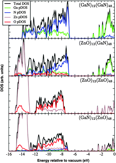
The DOS and its contributions from each element, partial DOS (pDOS), for the double bubbles are shown in Fig. 3. As expected, the valence electrons are localised on the anions and the lowest unoccupied states are localised on the cations. Of particular interest are the electronic states for the mixed system. Of the two possibilities, a ZnO inner shell (and GaN outer shell) results in both frontier electronic orbitals on GaN, whereas (GaN)12@(ZnO)48 has the desired separation of states: LUMO localised on zinc and HOMO is dominated by nitride states. To verify these predictions we explored the charge distribution of both charge carriers. Their spin densities obtained for singly ionised clusters are shown in Fig. 4, which confirms our above conclusions.
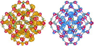 | ||
| Fig. 4 Electron (left) and hole (right) spin-density isoplots for (GaN)12@(ZnO)48. The hole is localised predominantly in the inner bubble and on the N atoms, whereas the electron on the outer bubble is localised on the Zn atoms. Atom colours are as in Fig. 1, hole isodensity shown in blue and electron in mustard yellow. Graphics were generated using the VESTA package.48 | ||
We now consider a periodic system of n = 60 double bubbles and two extended systems, LTA and SOD, formed from the n = 12 sodalite single-bubble SBU. The enthalpies of formation of these framework systems from the pure, ZnO and GaN, wurtzite phase, are shown in Table 2. As found for the individual SBU clusters, pure ZnO frameworks have the lowest enthalpies of formation; 0.19, 0.27 and 0.32 eV per ZnO, for the SOD, double bubble and LTA frameworks, respectively. Although the greater stability of SOD manifests itself in a lower value of the enthalpy of forming the pure GaN SOD system than any of the mixed systems, the mixed double bubble systems are more stable than the mixed (ZnO,GaN) SOD system. The latter should be attributed to the strain caused by the mismatch of ZnO and GaN SBU. The LTA and double bubble frameworks of GaN have the greatest values of Hf by at least ∼0.2 eV per formula unit.
| System | W VB (eV) | E g (eV) | H f (kJ mol−1) |
|---|---|---|---|
| (GaN)12–LTA | 6.89 | 3.94 | 58.86 |
| (GaN)12@(GaN)48 | 7.58 | 3.49 | 55.00 |
| (ZnO,GaN)12–LTA | 8.09 | 3.24 | 47.28 |
| (ZnO,GaN)12–SOD | 7.56 | 3.83 | 44.38 |
| (ZnO)12@(GaN)48 | 7.95 | 3.64 | 42.45 |
| (GaN)12@(ZnO)48 | 7.75 | 3.14 | 36.66 |
| (GaN)12–SOD | 7.65 | 3.43 | 33.77 |
| (ZnO)12–LTA | 7.49 | 3.91 | 30.88 |
| (ZnO)12@(ZnO)48 | 7.24 | 3.57 | 26.05 |
| (ZnO)12–SOD | 7.55 | 3.29 | 18.33 |
| ZnO wurtzite | 6.89 | 3.07 | 0.00 |
| GaN wurtzite | 7.72 | 3.86 | 0.00 |
Calculated parameters of the electronic band structure are also shown in Table 2. For the wurtzite phase of ZnO our calculations underestimate the band gap, which from low-temperature experimental measurement is 0.37 eV higher at 3.44 eV. The wurtzite GaN band gap is overestimated in contrast with the experimental value of 3.50 eV lying 0.36 eV below that obtained from our calculations. The wurtzite phase of ZnO has the smallest band gap of 3.07 eV, whereas the band gap for GaN, of 3.86 eV, is only the third largest, lying below the LTA frameworks of ZnO (3.91 eV) and GaN (3.94 eV). For ZnO, the band gap of SOD is greater than that of wurtzite, whereas, conversely, GaN SOD has a smaller band gap compared to wurtzite. Mixing n = 12 cages leads to an increase (∼0.4 eV) in the band gap in the case of edge sharing (SOD) frameworks and a decrease (∼0.7 eV) for corner sharing (LTA) frameworks. As expected, the band gap of LTA and SOD for ZnO is smaller than that predicted for the equivalent GaN phase. However, the reverse is found for the double bubble system: the band gap of (ZnO)12@(ZnO)48 is 0.08 eV greater than that of (GaN)12@(GaN)48. Mixing compositions results in the greatest and smallest band gaps for the double bubble frameworks, in the cases of the inner and outer cages formed by ZnO, respectively.
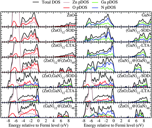
The DOS and pDOS of the periodic pure systems are plotted in the upper panels of Fig. 5 as calculated using a plane-wave basis set. These figures show that the DOS and pDOS for ZnO–SOD, –LTA –wurtzite structures share similar spectroscopic features. In fact, the top of the valence band in all ZnO structures is dominated by oxygen, whereas for the equivalent GaN systems it is dominated by nitrogen. Apart from the double bubble framework (where there are larger contributions from zinc and nitrogen), the bottom of the conduction band displays a flat and low DOS, which, for the bulk wurtzite systems, is known to be due to the high curvature of the conduction bands.49
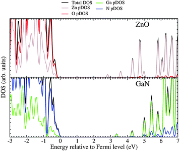
For the mixed systems (lower panels in Fig. 5), typically, the states nearest to the band gap appear to be dominated by nitrogen, which is puzzling for the unoccupied states. A similar observation can be made for the ZnO conduction bands. A more careful consideration of these states reveals that in fact the anionic attributions are overestimated, which is a consequence of the method of projecting the Bloch orbitals inside atomic spheres that have the covalent radii of the constituent elements – the method employed within the VASP code. Using true numerical atomic orbitals, which typically overlap significantly for higher energy metal valence states, as implemented in the FHI-aims code, we observed practically a complete electron transfer from anions to cations on excitation for wurtzite phases – see Fig. 6. Electron and hole spin-density isoplots for (ZnO,GaN)12–LTA and (ZnO,GaN)12–SOD are shown in the lower panels of Fig. 7. The hole for LTA is concentrated on 2p-orbitals of nitrogen and 2p-orbitals of oxygen atoms that are bonded to at least one gallium atom, and partially spill over on zinc atoms that interface between oxygen and nitrogen (effect of orthogonalisation). The hole for SOD is on orbitals of nitrogen; each envelope of spin density is shaped as a torus with axis of ring aligned through the neighbouring zinc atom. Although there are significant contributions on anions, the excited electron for LTA is also (asymmetrically) localised on zinc. These lobes point into the (ZnO)12 SBU; decreasing the isodensity the electron is seen to concentrate inside these ZnO SBU, and not within the GaN SBU and the larger inter-cage voids – see Fig. 8. Returning to Fig. 7, a similar picture for the excited electron of LTA is found for SOD, except that the contribution on zinc is more pronounced in the form of half a torus about each zinc atom, which is not bonded to a nitrogen atom.
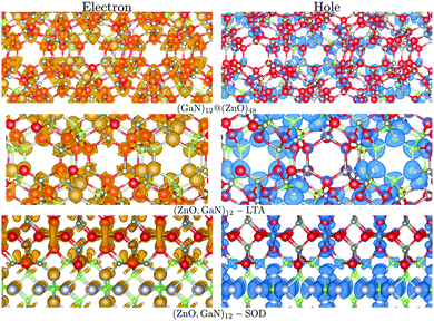 | ||
| Fig. 7 Electron (left) and hole (right) spin-density isoplots for (GaN)12@(ZnO)48, (ZnO,GaN)12–SOD and (ZnO,GaN)12–LTA systems. The hole is localised predominantly in the inner bubble and on the N atoms, whereas the electron on the outer bubble is localised on the Zn atoms. Colours are as in Fig. 4 and graphics were generated using the VESTA package.48 | ||
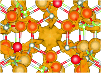 | ||
| Fig. 8 Electron distribution at the bottom of the conduction band of (ZnO,GaN)12–LTA. Note the isodensity concentration around Zn atoms forming semi-torus lobes and converging towards the centre of (ZnO)12 SBU void, which indicates electron–hole separation by a different mechanism compared to the other frameworks. Colours are as in Fig. 4 and graphics were generated using the VESTA package.48 | ||
An important clear exception to the trends discussed above, and where there is no confusion due to the chosen method of projecting, occurs for the double bubble frameworks with (GaN)12 inner cages and (ZnO)48 outer cages: the edge of the conduction band is clearly dominated by zinc, and there appears a distinct split peak at the top of the valence band, which is attributed to nitrogen. Thus, we have the condition for separation of hole (on nitrogen atoms, which are in the inner cages) and excited electron (onto zinc atoms, which are in the outer cages) fulfilled. In contrast, the inverse system (ZnO)12@(GaN)48 has both a higher energy of formation and no separation between holes and electrons – all charged carriers are localised on the GaN component of the lattice.
Electron and hole spin-density isoplots for (GaN)12@(ZnO)48 are shown in the top panels of Fig. 7. The electron can be seen to occupy the diffuse zinc 3s orbitals, which overlap with each other while avoiding regions occupied by valence electrons (effect of orthogonalisation). Therefore, envelopes of spin density around anions and incomplete spherical shells about zinc atoms are apparent. The hole is concentrated on 2p orbitals of nitrogen with partial spill over to oxygen 2p states, which could be attributed to artefacts of self-interaction still remaining at this level of theory.
4. Conclusions
We propose that novel composite systems comprised of double bubbles along with superlattices of single-shell bubbles could provide a suitable way of generating electron–hole separation for photocatalysis. We found that hole and electron separation would be achieved most efficiently by the edge sharing framework composed of the (GaN)12@(ZnO)48 double bubbles, which have relatively low enthalpy of formation,16 and are comparable to the formation of fullerene (C60) with respect to bulk carbon (ca. 40 kJ mol−1).17,18 Synthetic routes have already been established for reliable core–shell nanostructure fabrication and layered structures are well known for analogous pure compounds (BN, ZnO and MoS2)19,23,50 therefore it is plausible that (GaN)12@(ZnO)48 will be achievable in the near future. Indeed, the synthesis of In1−xGaxN@ZnO has been reported, with the aim of achieving quantum dot integrated solar harvesting materials.51 Although the band gaps for the double bubble materials are larger than bulk ZnO, the efficient hole and electron separation should improve their performance relative to the bulk counterparts as an ultra violet photocatalyst.Acknowledgements
We thank kindly our former collaborators Said Hamad, Eleonora Spano, Stefan T. Bromley, Stephen A. Shevlin, Matthew B. Watkins, and Abdullah A. Al-Sunaidi, discussions with whom have been inspiring and instrumental for us undertaking this research. We are grateful for the insight gained from discussions on the nature of conduction states in oxides with Sanliang Ling.We also thank EPSRC for providing the funding for M.R.F. and S.M.W. on grant numbers EP/I03014X and EP/K038958; J.B. and A.A.S. on grant number EP/IO1330X; and A.J.L. on grant number EP/I030662. The authors also acknowledge the use of the UCL Legion High Performance Computing Facility (Legion@UCL) and associated support services; the IRIDIS cluster provided by the EPSRC funded Centre for Innovation (EP/K000144 and EP/K000136); this work made use of the facilities of HECToR and ARCHER, the UK's national high-performance computing service through membership of the UK's HPC Materials Chemistry Consortium, which is funded by EPSRC (EP/L000202).
Notes and references
- S. Nakamura, S. Pearton and G. Fasol, The blue laser diode: the complete story, Springer-Verlag, Berlin Heidelberg, 2nd revised edn, 2000 Search PubMed.
- A. Fujishima and K. Honda, Nature, 1972, 238, 37–38 CrossRef CAS.
- A. Fuertes, J. Mater. Chem., 2012, 22, 3293–3299 RSC.
- Y. Moriya, T. Takata and K. Domen, Coord. Chem. Rev., 2013, 257, 1957–1969 CrossRef CAS PubMed.
- K. Maeda, T. Takata, M. Hara, N. Saito, Y. Inoue, H. Kobayashi and K. Domen, J. Am. Chem. Soc., 2005, 127, 8286–8287 CrossRef CAS PubMed.
- R. D. Vispute, V. Talyansky, S. Choopun, R. P. Sharma, T. Venkatesan, M. He, X. Tang, J. B. Halpern, M. G. Spencer, Y. X. Li, L. G. Salamanca-Riba, A. A. Iliadis and K. A. Jones, Appl. Phys. Lett., 1998, 73, 348–350 CrossRef CAS PubMed.
- Q.-X. Yu, B. Xu, Q.-H. Wu, Y. Liao, G.-Z. Wang, R.-C. Fang, H.-Y. Lee and C.-T. Lee, Appl. Phys. Lett., 2003, 83, 4713–4715 CrossRef CAS PubMed.
- H. Zhu, C.-X. Shan, B. Yao, B.-H. Li, J.-Y. Zhang, Z.-Z. Zhang, D.-X. Zhao, D.-Z. Shen, X.-W. Fan, Y.-M. Lu and Z.-K. Tang, Adv. Mater., 2009, 21, 1613–1617 CrossRef CAS.
- E. M. Wong and P. C. Searson, Appl. Phys. Lett., 1999, 74, 2939–2941 CrossRef CAS PubMed.
- S. A. Shevlin, Z. X. Guo, H. J. J. van Dam, P. Sherwood, C. R. A. Catlow, A. A. Sokol and S. M. Woodley, Phys. Chem. Chem. Phys., 2008, 10, 1944–1959 RSC.
- C. R. A. Catlow, S. A. French, A. A. Sokol, A. A. Al-Sunaidi and S. M. Woodley, J. Comput. Chem., 2008, 29, 2234–2249 CrossRef CAS PubMed.
- C. R. A. Catlow, S. T. Bromley, S. Hamad, M. Mora-Fonz, A. A. Sokol and S. M. Woodley, Phys. Chem. Chem. Phys., 2010, 12, 786–811 RSC.
- M. B. Watkins, S. A. Shevlin, A. A. Sokol, B. Slater, C. R. A. Catlow and S. M. Woodley, Phys. Chem. Chem. Phys., 2009, 11, 3186–3200 RSC.
- S. M. Woodley, M. B. Watkins, A. A. Sokol, S. A. Shevlin and C. R. A. Catlow, Phys. Chem. Chem. Phys., 2009, 11, 3176–3185 RSC.
- J. Carrasco, F. Illas and S. T. Bromley, Phys. Rev. Lett., 2007, 99, 235502 CrossRef.
- M. Farrow, J. Buckeridge, C. Catlow, A. Logsdail, D. Scanlon, A. Sokol and S. Woodley, Inorganics, 2014, 2, 248–263 CrossRef PubMed.
- R. F. Curl and R. C. Haddon, Philos. Trans. R. Soc., A, 1993, 343, 19–32 CrossRef CAS.
- H. P. Diogo, M. E. M. da Piedade, T. J. S. Dennis, J. P. Hare, H. W. Kroto, R. Taylor and D. R. M. Walton, J. Chem. Soc., Faraday Trans., 1993, 89, 3541–3544 RSC.
- F. Jensen and H. Toftlund, Chem. Phys. Lett., 1993, 201, 89–96 CrossRef CAS.
- D. Golberg, Y. Bando, O. Stephan and K. Kurashima, Appl. Phys. Lett., 1998, 73, 2441–2443 CrossRef CAS.
- A. Kasuya, R. Sivamohan, Y. A. Barnakov, I. M. Dmitruk, T. Nirasawa, V. R. Romanyuk, V. Kumar, S. V. Mamykin, K. Tohji, B. Jeyadevan, K. Shinoda, T. Kudo, O. Terasaki, Z. Liu, R. V. Belosludov, V. Sundararajan and Y. Kawazoe, Nat. Mater., 2004, 3, 99–102 CrossRef CAS PubMed.
- S. Botti and M. A. L. Marques, Phys. Rev. B: Condens. Matter Mater. Phys., 2007, 75, 035311 CrossRef.
- A. N. Enyashin, S. Gemming, M. Bar-Sadan, R. Popovitz-Biro, S. Y. Hong, Y. Prior, R. Tenne and G. Seifert, Angew. Chem., Int. Ed., 2007, 46, 623–627 CrossRef CAS PubMed.
- P. A. Parilla, A. C. Dillon, K. M. Jones, G. Riker, D. L. Schulz, D. S. Ginley and M. J. Heben, Nature, 1999, 397, 114 CrossRef CAS PubMed.
- R. Tenne, M. Homyonfer and Y. Feldman, Chem. Mater., 1998, 10, 3225–3238 CrossRef CAS.
- B. O. Dabbousi, J. RodriguezViejo, F. V. Mikulec, J. R. Heine, H. Mattoussi, R. Ober, K. F. Jensen and M. G. Bawendi, J. Phys. Chem. B, 1997, 101, 9463–9475 CrossRef CAS.
- R. G. Chaudhuri and S. Paria, Chem. Rev., 2012, 112, 2373–2433 CrossRef PubMed.
- K. Momma and F. Izumi, J. Appl. Crystallogr., 2008, 41, 653 CrossRef CAS.
- S. T. Bromley, CrystEngComm, 2007, 9, 463–466 RSC.
- W. Sangthong, J. Limtrakul, F. Illas and S. T. Bromley, J. Mater. Chem., 2008, 18, 5871–5879 RSC.
- M. A. Zwijnenburg, F. Illas and S. T. Bromley, Phys. Rev. Lett., 2010, 104, 175503 CrossRef.
- Y. L. Yong, B. Song and P. M. He, Phys. Chem. Chem. Phys., 2011, 13, 16182–16189 RSC.
- Z. Liu, X. Wang, J. Cai, G. Liu, P. Zhou, K. Wang and H. Zhu, J. Phys. Chem. C, 2013, 117, 17633–17643 CAS.
- Z. F. Liu, X. Q. Wang and H. J. Zhu, RSC Adv., 2013, 3, 1450–1459 RSC.
- C. Baerlocher, L. B. McCusker and C. H. Olson, Atlas of Zeolite Framework Types, Elsevier, Amsterdam, 6th revised edn, 2007 Search PubMed.
- C. Mellot-Draznieks, S. Girard, G. Ferey, J. C. Schon, Z. Cancarevic and M. Jansen, Chem. – Eur. J., 2002, 8, 4103–4113 CrossRef.
- J. D. Gale and A. L. Rohl, Mol. Simul., 2003, 29, 291–341 CrossRef CAS.
- L. Whitmore, A. A. Sokol and C. R. A. Catlow, Surf. Sci., 2002, 498, 135–146 CrossRef CAS.
- J. P. Perdew, K. Burke and M. Ernzerhof, Phys. Rev. Lett., 1996, 77, 3865 CrossRef CAS.
- J. P. Perdew, A. Ruzsinszky, G. I. Csonka, O. A. Vydrov, G. E. Scuseria, L. A. Constantin, X. Zhou and K. Burke, Phys. Rev. Lett., 2008, 100, 136406 CrossRef.
- V. Blum, R. Gehrke, F. Hanke, P. Havu, V. Havu, X. G. Ren, K. Reuter and M. Scheffler, Comput. Phys. Commun., 2009, 180, 2175–2196 CrossRef CAS.
- E. Vanlenthe, E. J. Baerends and J. G. Snijders, J. Chem. Phys., 1994, 101, 9783–9792 CrossRef CAS PubMed.
- G. Kresse and J. Hafner, Phys. Rev. B: Condens. Matter Mater. Phys., 1993, 47, 558–561 CrossRef CAS.
- G. Kresse and J. Hafner, Phys. Rev. B: Condens. Matter Mater. Phys., 1994, 49, 14251–14269 CrossRef CAS.
- G. Kresse and J. Furthmüller, Comput. Mater. Sci., 1996, 6, 15–50 CrossRef CAS.
- G. Kresse and J. Furthmüller, Phys. Rev. B: Condens. Matter Mater. Phys., 1996, 54, 11169–11186 CrossRef CAS.
- P. E. Blöchl, Phys. Rev. B: Condens. Matter Mater. Phys., 1994, 50, 17953–17979 CrossRef.
- K. Momma and F. Izumi, J. Appl. Crystallogr., 2011, 44, 1272–1276 CrossRef CAS.
- S. Bloom and I. Ortenburger, Phys. Status Solidi B, 1973, 58, 561–566 CrossRef CAS.
- E. C. Behrman, R. K. Foehrweiser, J. R. Myers, B. R. French and M. E. Zandler, Phys. Rev. A: At., Mol., Opt. Phys., 1994, 49, R1543–R1546 CrossRef CAS.
- S. Rajaambal, M. Mapa and G. S. Chinnakonda, Dalton Trans., 2014 10.1039/C4DT01268B.
| This journal is © the Owner Societies 2014 |

