 Open Access Article
 This Open Access Article is licensed under a Creative Commons Attribution-Non Commercial 3.0 Unported Licence
Mono- and co-doped NaTaO3 for visible light photocatalysis
Pushkar
Kanhere
a,
Prathamesh
Shenai
b,
Sudip
Chakraborty
c,
Rajeev
Ahuja
cd,
Jianwei
Zheng
e and
Zhong
Chen
*ab
aEnergy Research Institute @ NTU, 1 CleanTech Loop, CleanTech One, Singapore 637141. E-mail: aszchen@ntu.edu.sg
bSchool of Materials Science and Engineering, Nanyang Technological University, Block N4.1, 50 Nanyang Avenue, Singapore 639798
cApplied Materials Physics, Department of Materials and Engineering, Royal Institute of Technology (KTH), S-100 44 Stockholm, Sweden
dCondense Matter Theory Group, Department of Physics and Astronomy, Uppsala University, Box 516, 751 20 Uppsala, Sweden
eInstitute of High Performance Computing, 1 Fusionopolis Way, #16-16 Connexis, Singapore 138632
First published on 9th June 2014
Abstract
Electronic structures of doped NaTaO3 compounds are of significant interest to visible light photocatalysis. This work involves the study of the band gap, band edge potentials, and thermodynamic stability of certain mono-doped and co-doped NaTaO3 systems, using DFT-PBE as well as hybrid (PBE0) functional calculations. Doping of certain non-magnetic cations (Ti, V, Cu, Zn, W, In, Sn, Sb, Ce, and La), certain anions (N, C, and I), and certain co-dopant pairs (W–Ti, W–Ce, N–I, N–W, La–C, Pb–I, and Cu–Sn) is investigated. Our calculations suggest that substitutional doping of Cu at the Ta site, Cu at the Na site, and C at the O site narrows the band gap of NaTaO3 to 2.3, 2.8, and 2.1 eV, respectively, inducing visible light absorption. Additionally, passivated co-doping of Pb–I and N–W narrows the band gap of NaTaO3 to the visible region, while maintaining the band potentials at favorable positions. Hybrid density of states (DOS) accurately describe the effective band potentials and the location of mid-gap states, which shed light on the possible mechanism of photoexcitation in relation to the photocatalysis reactions. Furthermore, the thermodynamic stability of the doped systems and defect pair binding energies of co-doped systems are discussed in detail. The present results provide useful insights into designing new photocatalysts based on NaTaO3.
1. Introduction
Photocatalytic materials are extensively studied because of their various applications such as solar hydrogen generation, reduction of carbon dioxide, degradation of volatile organic compounds, and inhibition of micro-organisms.1–4 Among various photocatalytic materials, perovskite type oxides containing d0 type cations viz. Ti, Nb, and Ta are known to be efficient photocatalysts for water splitting reaction.5,6 Particularly, NaTaO3 photocatalysts have gained significant attention as one of the most efficient photocatalytic material systems for stoichiometric water splitting under Ultra-Violet (UV) radiation. To narrow the band gap of NaTaO3 and utilize the solar radiation, doped NaTaO3 compounds have been recently studied. Doping of various elements such as Bi, Cu, N, and Fe has been studied to achieve visible light photocatalysis.7–12 Furthermore, co-doping of La–Co, La–Cr, La–Ir, and La–Fe in NaTaO3 was shown to be successful in visible light absorption and subsequent hydrogen evolution.12–16 These studies have indicated that both anion and cation doping in NaTaO3 is useful for visible light photocatalytic applications. As pristine NaTaO3 shows excellent photocatalytic activity under UV radiation,17 doped NaTaO3 is expected to show promising photocatalytic performance under visible light. Although a few doped systems are reported in the literature, the potential of NaTaO3 as a host material is not fully explored. In order to design such systems, the effect of various dopants on the band gap of NaTaO3 must be studied in detail. DFT based electronic structure calculations are useful in probing the band structure of doped photocatalytic systems. NaTaO3 is known to exist in orthorhombic and monoclinic forms and the electronic structures of both lattices were studied earlier.18,19 Among the doped NaTaO3 systems, a computational study on the anionic (N, F, P, Cl, and S) doping is reported by Han et al. This study shows that certain anions like N and P may be useful for visible light absorption.20 Additionally, doping of magnetic cations such as Mn, Fe, and Co in NaTaO3 has also been studied using DFT-PBE.21 The band structures of semiconductors and insulators calculated by DFT have the well known problem of band gap underestimation. GGA or LDA approximations do not describe the CB (empty) states accurately. The underestimation by the GGA functional could also result in describing impurity induced electronic states incorrectly.12 Therefore, an accurate description of the band structure of the doped photocatalyst could not be obtained by DFT calculations. These limitations of DFT could be overcome by using hybrid DFT calculations, where the band gaps are found to be close to the experimental values in certain cases. Hybrid calculations correctly assign the position of empty states and thus give an accurate description of the band structure. In our earlier work, we showed that hybrid DFT calculations provide useful insights into understanding the photocatalytic properties of La–Fe co-doped NaTaO3.12 Thus, the study of doped NaTaO3 using hybrid DFT calculations is useful in designing new systems for efficient photocatalysis.In this study, detailed investigation of the band structure of mono-doped and co-doped NaTaO3 is carried out by using DFT calculations. The effect of doping of certain anions such as N, C, and I and certain cations such as Ti, V, Cu, W, In, Sn, Sb, La, and Ce on the band structure of NaTaO3 is investigated in detail. Along with the mono-doped NaTaO3 structures, the effect of co-doping such as W–N, W–Ti, W–Ce, La–C, N–I, Sn–Cu, and Pb–I is also studied. The electronic structures of promising systems are studied using hybrid DFT calculations. The valence band structure, band alignment, and total energy of the above mentioned systems are discussed to identify potentially useful dopants for visible light photocatalysis.
2. Methods
2.1 Computational methods
The electronic structures of mono-doped and co-doped NaTaO3 were studied using Density Functional theory (DFT) based ab initio calculations. All the calculations were performed using CAmbridge Series Total Energy Package, (CASTEP)22 implemented in Materials Studio 5.0. The exchange–correlation functional was constructed using the Generalized Gradient Approximations (GGA) proposed by Perdew, Burke, and Ernzerhof (PBE).23 DFT is quite elegant to investigate the ground state electronic structure calculations. The optical band gap however, is an exited state phenomenon. The jump from the ground state to the excited state leads to the derivative discontinuity of the Kohn–Sham eigenvalue and hence the exchange–correlation functional is required to be modified beyond the local density approximation (LDA) and generalized gradient approximations (GGA). This modification to improve the quantum mechanical picture has been implemented by the use of a hybrid functional. In order to obtain accurate band gap values and band structure description, the hybrid functional PBE0 was used. This functional contains the combination of exact exchange and GGA approximation as represented in eqn (1).| EPBE0XC = ¼EHFX + ¾EPBEX + EPBEC, | (1) |
Here, EHFX is the Hartree–Fock (HF) exchange energy, EPBEX and EPBEC are the PBE exchange and correlation energies, respectively. An energy cutoff of 400 eV and a Monkhorst–Pack k-point mesh of 2 × 2 × 3 was found to be sufficient for geometry optimization of 2 × 2 × 1 supercell. For the calculation of the density of states a k-point mesh of 3 × 3 × 4 was used. A complete geometry optimization i.e. atomic positions and lattice parameters (a, b, and c) was carried out on the pristine and doped NaTaO3 structures. The forces on individual ions in the optimized structure were below 0.03 eV Å−1.
2.2 Computational models
The experimentally reported structure of orthorhombic NaTaO3 (space group no. 62 Pcmn),24 which is commonly studied for photocatalysis, was used as initial structure (Fig. 1). A supercell of 2 × 2 × 1, consisting of 80 atoms, was constructed and substitutional doping and co-doping of foreign elements were studied using this supercell. Substitution of an impurity ion at one of the cation sites accounts for 6.25% doping while a pair of co-dopants at two cationic sites accounts for doping of 12.5% by moles. Similarly anionic doping in this supercell corresponds to 1.56% of doping. In order to understand the changes in the band structure upon doping, total density of states and site projected partial density of states (s, p, and d orbitals) of pure and doped structures were plotted.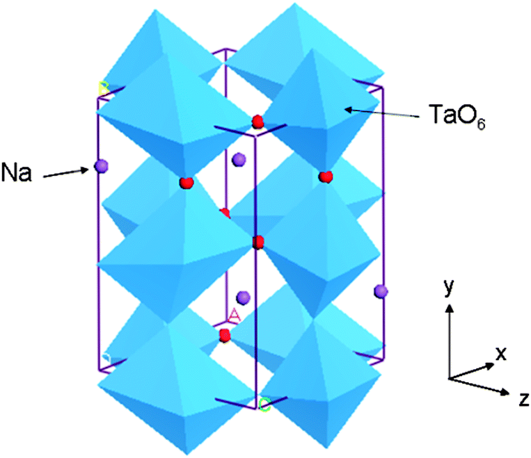 | ||
| Fig. 1 An orthorhombic unit cell of NaTaO3. | ||
3. Results and discussion
3.1 Density of states of the pristine NaTaO3
Analysis of the density of states (DOS) of pristine NaTaO3 shows that top of the valence band (VB) is predominantly composed of O 2p while the conduction band (CB) mainly consists of Ta 5d orbitals. Thus, upon photoexcitation transition of electrons from O 2p to empty Ta 5d occurs. The band gap value obtained by GGA-PBE calculations was 2.13 eV, which is comparable with the other computational studies on NaTaO3.19 However, this value is severely underestimated as compared to the experimental band gap value. The band gap value obtained from the PBE0 (hybrid) functional was 4.2 eV, which is in excellent agreement with the experimental reports. PDOS obtained from PBE0 calculations are shown in Fig. 2. A direct type band gap is seen from the band structure, where the minima and the maxima of the bands occur at the Γ point in the reciprocal lattice. The lattice parameters calculated using GGA-PBE (5.5335 Å, 5.5784 Å and 7.7869 Å) are in good agreement with the experimentally reported data.24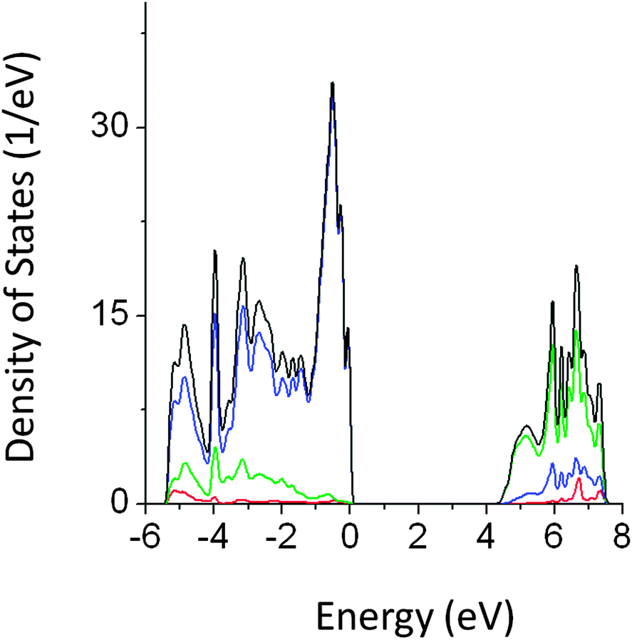 | ||
| Fig. 2 Total and partial density of states (DOS) of pristine NaTO3 calculated using the PBE0 functional (red s; blue p; green d, black total). | ||
3.2 Doping of Cu
Doping of magnetic (3d) cations such as Mn, Cr, Fe, and Co in NaTaO3 has been studied using DFT calculations as well as experiments.21 It is known that these cations strongly influence the valence band structure of NaTaO3 and are useful in inducing visible light absorption. However, little is known about the non-magnetic cation doping in NaTaO3. Dopants such as Cu, Zn, W, and Ce are commonly used to alter the electronic and optical properties of functional oxides.25,26 Recently, Cu doped NaTaO3 has been reported to cause hydrogen evolution under visible light, making this system a promising visible light photocatalyst.9 The role of Cu ions in the NaTaO3 lattice is not well understood and our calculations shed light on the changes in the electronic structure of NaTaO3 when Cu is doped at the Ta or Na site in the lattice.Fig. 3 shows the partial density of states of Cu doped at the Ta site in NaTaO3 (NaTa1−xCuxO3, x = 0.0625). Doping of Cu at the Ta site produces band-like states approximately 1.0 eV above the valence band maximum. Although the mid-gap states occur in between the band gap, these states are not occupied by electrons. Thus, for the perfect crystal of Cu doped NaTaO3, the energy gap between the VBM and mid-gap states is 1.2 eV, while the band gap between VBM and CBM is increased to 4.8 eV.
 | ||
| Fig. 3 Total and partial density of states of Cu doped (Ta site) NaTaO3 calculated using the hybrid (PBE0) functional (red s; blue p; green d, black total). | ||
In this case, the electronic excitation from the VBM to mid-gap states is possible; however, it may not be suitable for the photocatalytic hydrogen generation. It is likely that the mid-gap states might get occupied by electrons due to the point defects present in the lattice. In such a case, the effective band gap (mid-gap to CBM) is estimated to be 2.3 eV. Site projected PDOS show that the mid-gap states are composed of Cu 3d and O 2p, while contributions from Ta and Na are insignificant. The electronic structure of Cu doped NaTaO3 calculated using GGA-PBE shows that Cu 3d states appear above VBM, which are connected to the VBM. However, hybrid calculations accurately place the mid gap states around 1.0 eV above the VBM, revealing the true nature of the band structure.
The experimental report on NaTa1−xCuxO3 shows extension of the absorption spectra into the visible region and shows subsequent hydrogen evolution.10 This result agrees with the band structure studies in the present report.
The ionic radius of Cu1+ is close to that of Na1+ and hence doping of Cu at the Na site is possible. Therefore, we have studied the effect of Cu doping at the Na site on the band structure of NaTaO3. The band gap narrowing of around 1.2 eV was seen for Cu doping at Na sites as seen from the PDOS plots shown in Fig. 4. Cu 3d induced energy states appear at 1.0 and 1.5 eV above the VBM. The mid-gap states in this case are predominantly formed by Cu 3d orbitals, while some contributions from O 2p are seen. These energy states are partially occupied and thus electronic transition from mid-gap states to CBM is possible by visible light excitation. Our calculations reveal that doping of Cu at both Na and Ta sites independently narrows the effective band gap and induces visible light absorption in NaTaO3. It is noted that Cu doping at the Na site produces partially occupied mid-gap states, as compared to Cu doped at the Ta site. Therefore, doping of Cu at the Na site is more promising than that of Cu at the Ta site. Earlier experimental and theoretical work on Cu doped Na2Ta4O11 photocatalysts revealed that Cu1+ is preferentially doped at the Na site and contributes to significant band gap narrowing.27 These results corroborate the present findings on Cu doping at the Na site.
 | ||
| Fig. 4 Total and partial density of states of Cu doped (Na site) NaTaO3 calculated using the hybrid (PBE0) functional (red s; blue p; green d, black total). | ||
3.3 Doping of V, W, Ti, and Zn
Doping of V, W, Ti, and Zn at the Ta site in NaTaO3 has been investigated in this study. It was found that V doping led to increment in the band gap by 0.2 eV. V 3d induced energy appeared at the CBM pushing the effective band edge potential to more negative values by around 0.2 eV (Fig. 5). It is worth noting that NaVO3 has a band gap of 3.1 eV, while doping of V at the Ta site increased the band gap of NaTaO3.28 Thus, though V doping at the Ta site maintains the ionic charge balance, V doping is not useful for visible light absorption. | ||
| Fig. 5 Total and partial density of states of V doped NaTaO3, calculated using the PBE0 functional, (red s; blue p; green d, black total). | ||
Doping of W at the Ta site reduced the band gap by 0.6 eV, which is not useful for the visible light absorption. As shown in Fig. 6, W 6s induced states appear below the CBM, shifting the conduction band potential to more positive values. PDOS analysis showed that newly created energy states are mainly composed of W 6s + O 2p orbitals. W doping shifts the Fermi energy at the bottom of the CBM, suggesting possible metallic behavior. Both PBE and PBE0 calculations suggest reduction in the effective band gap value by around 0.6 eV.
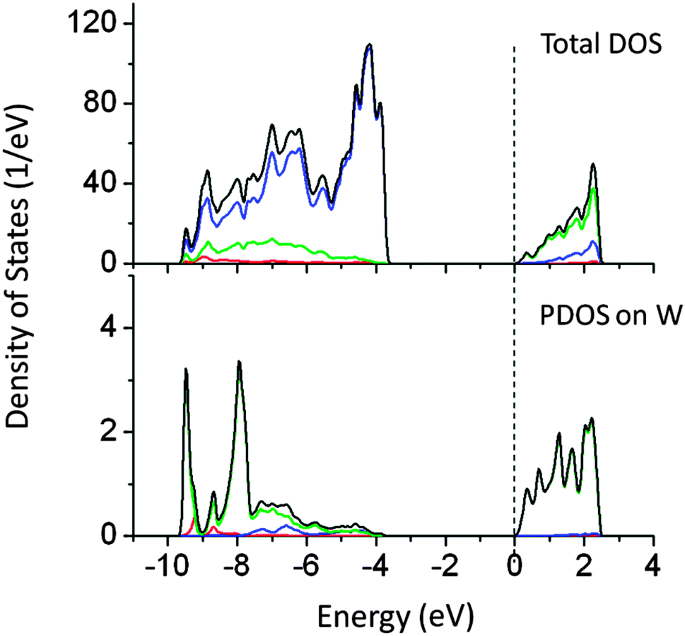 | ||
| Fig. 6 Total and partial density of states of doping W doped (Ta site) NaTaO3 calculated using the hybrid (PBE0) functional, (red s; blue p; green d, black total). | ||
Our calculations revealed that doping of Ti and Zn at the Ta site does not alter the band gap significantly. Ti and Zn produced extra energy states above the VBM. The PDOS of Ti and Zn doped NaTaO3 are shown in Fig. 7. The band gap narrowing by Ti and Zn is limited to 0.3 and 0.15 eV, respectively. As the effect of these dopants on the band gap is negligible, these systems have not been studied by hybrid functionals. The band gaps calculated using DFT-PBE have been corrected by using a scissor operator of 1.8 eV for comparison.
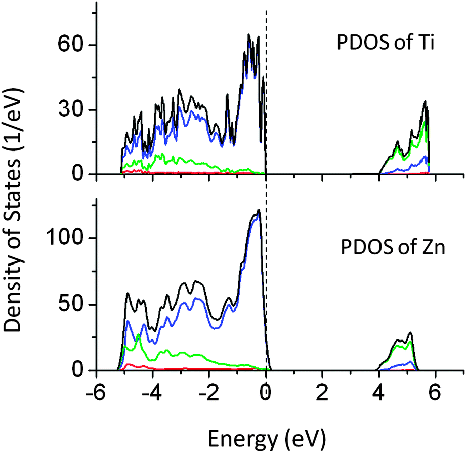 | ||
| Fig. 7 Total and partial density of states of Ti and Zn doped NaTaO3, calculated using the GGA-PBE functional (scissor operator applied) (red s; blue p; green d, black total). | ||
3.4 Doping of In, Sn, Sb, La, and Ce
Bismuth doping in Tantalates such as NaTaO3 and Na2Ta2O6 has shown visible light driven photocatalytic reactions.11 However, the effect of other p-block elements on NaTaO3 has not been studied. Thus we have investigated the effect of doping of In, Sn, and Sb at the Ta site in the NaTaO3 lattice. Doping of In, Sn, and Sb produced a small alteration in the band gap of NaTaO3 as shown in Fig. 8. As the effect of these dopants on the band gap is insignificant, these systems are studied by GGA-PBE calculations. The band gap values are further corrected by applying a scissor operator of 1.8 eV. In our earlier work, we showed that doping of Bi at Na and Ta sites in NaTaO3 induces intense visible light absorption. This effect of band gap narrowing was attributed to the lone pair of electrons in Bismuth. However, in the present p block elements studied, no significant effect on the band gap was seen. | ||
| Fig. 8 Total and partial density of states of (p block) In, Sn, and Sb doped NaTaO3, calculated using the GGA-PBE functional (scissor operator applied) (red s; blue p; green d, black total). | ||
Finally, doping of La at the Na site and Ce at the Ta site in NaTaO3 was studied. It was revealed that both Ce and La increase the band gap by 0.1 and 0.2 eV, respectively. These results are in good agreement with the earlier reports on La doped NaTaO3.29 These systems are studied using GGA-PBE calculations and the band gap values are further corrected by applying a scissor operator of 1.8 eV. Fig. 9 shows PDOS of La and Ce doped NaTaO3. PDOS analysis shows that La 5d and Ce 4f induced energy states appear at the CBM. Although these elements do not affect the band gap of NaTaO3 significantly, they could be used as co-dopants. Therefore, it is important to know their effect on the electronic structure of NaTaO3.
 | ||
| Fig. 9 Total and partial density of states of La and Ce doped NaTaO3, calculated using the GGA-PBE functional (scissor operator applied) (red s; blue p; green d, pink f; black total). | ||
As the doping concentration of cations is significant (i.e. 6.25%), doping of aliovalent ions is likely to change the semiconductor/ceramic behavior of NaTaO3 to metallic form. However, such a change is strongly correlated with the dopant induced point defects in the lattice. It is worth noting that the present calculations are done to understand the effect of dopants on the band structure in the pristine lattice, where the effect of point defects is not studied. Representing the real structures is a complex problem and out of scope of the current work.
3.5 Doping of I, N, and C
In our earlier article, the effect of anionic doping on the band gap of NaTaO3 was reported in detail.30 In this article, the results of selected anions which are used as co-dopants in this study are briefly discussed. Anionic doping has been proved to be successful for inducing the visible light absorption in photocatalysts such as SrTiO3 and TiO2.31–33 N doped NaTaO3 nanoparticles and thin films have been reported to show visible light driven photocatalytic activity.34,35 Recently, I doped NaTaO3 has been studied for degradation of MB under visible light.36 The origin of visible light absorption and the possible mechanism of photoexcitation should be investigated in new systems such as I doped NaTaO3. Fig. 10 shows the partial and total density of states of I, N, and C doped NaTaO3 calculated using the hybrid functional (PBE0).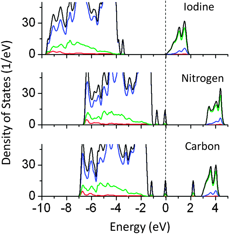 | ||
| Fig. 10 Total and partial density of states of I, N, and C doped NaTaO3 calculated using the hybrid (PBE0) functional, (red s; blue p; green d, black total). | ||
PDOS plots show that doping of I, N, and C at oxygen sites reduces the effective band gap of NaTaO3 by 0.7, 0.9, and 2.0 eV, respectively. The site projected PDOS plots of anion doped NaTaO3 are shown in Fig. 11. In the case of Iodine doping, I 5s induced energy states appear above the VBM, shifting the effective VB energy to more negative values. The Fermi energy in this case is at the bottom of the CB. The PDOS plots show that N doping at the O site creates electronic states composed of N 2p and O 2p above the VBM. When N doping was studied using GGA-PBE calculations, two different energy states near the VB did not appear. However, the hybrid calculations reveal the presence of two distinct energy peaks appearing above the VBM. Such band structures suggest that upon visible light irradiation, the electronic transition from partially filled mid-gap states to the CBM occurs. Thus, only the energy states near the Fermi energy are useful for visible light excitation. Experimental work on N doping in NaTaO3 indeed shows a change in the band gap from 4.0 eV to 3.7 eV, while the tail of the UV-VIS spectra extended up to 2.25 eV.35
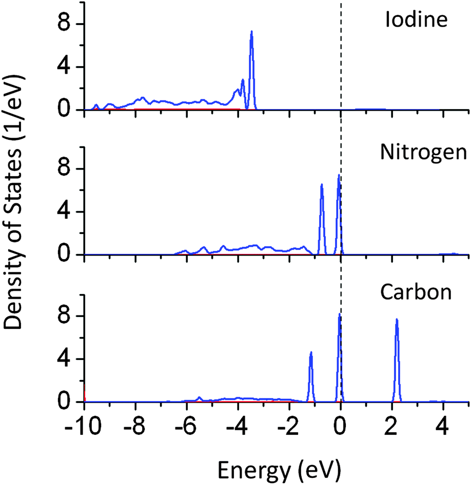 | ||
| Fig. 11 Partial density of states of I, N, and C doped NaTaO3 decomposed on dopant sites (PBE0 functional) (red s; blue p; green d, black total). | ||
PDOS plots of C doping at the O site show that C doping induces C 2p derived energy states in between the band gap. C 2p induced energy states appear above the VBM (occupied) as well as above and below the CBM (unoccupied), giving rise to effective band gap values of 2.0 and 2.8 eV respectively. Photoexcitation from occupied C 2p states to unoccupied C 2p states (2.0 eV) would occur in the presence of visible light; however the photo-excited electron would be highly localized on the C site and may not be beneficial for photoexcited reactions. On the other hand, the photoexcitation from occupied C 2p states to the CBM would prove to be useful for the photocatalytic reactions. This electronic transition corresponds to 2.8 eV. Therefore, although C doping reduces the effective band gap of NaTaO3, it is revealed by PBE0 calculations, that not all electronic transitions are useful for photoexcitation.
3.6 Co-doping in NaTaO3
Passivated co-doping is one of the known strategies to narrow the band gap and maintain the ionic charge balance in a lattice. Several co-doped systems are known to improve the performance of visible light driven photocatalytic activity.14,37,38 In this work, the co-doping of N–W, W–Ce, W–Ti, N–I, La–C, Cu–Sn, and Pb–I has been studied. The specific pairs of dopants are selected to maintain the ionic charge balance in a NaTaO3 lattice. Co-doping of W and Ti and co-doping of W and Ce at the Ta site did not alter the band gap significantly. Fig. 12 shows the total DOS of W–Ti and W–Ce co-doped NaTaO3. In these cases, no synergistic effects were observed, indicating that these pairs are not useful for visible light absorption in NaTaO3.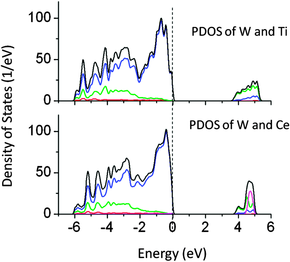 | ||
| Fig. 12 Total and partial density of states of co-doped W–Ti and W–Ce co-doped NaTaO3, calculated using the GGA-PBE functional (scissor operator applied) (red s; blue p; green d, pink f; black total). | ||
The band gap reduction in W–Ti and W–Ce co-doped NaTaO3 was found to be 0.5 and 0.4 eV respectively. Fig. 13 shows partial density of states of La and C doped NaTaO3. In this case, La is substituted at the Na site while C is substituted at the O site to nullify the dopant induced charge imbalance. Density of states show that co-doping La and C induces mid-gap states, which are spread over 1.5 eV, exhibiting a band like behavior. Site decomposed DOS shows that these energy states are mainly contributed by C 2p and O 2p states, narrowing the total band gap by around 2.4 eV. The contributions from La 5d were negligible in the mid-gap states.
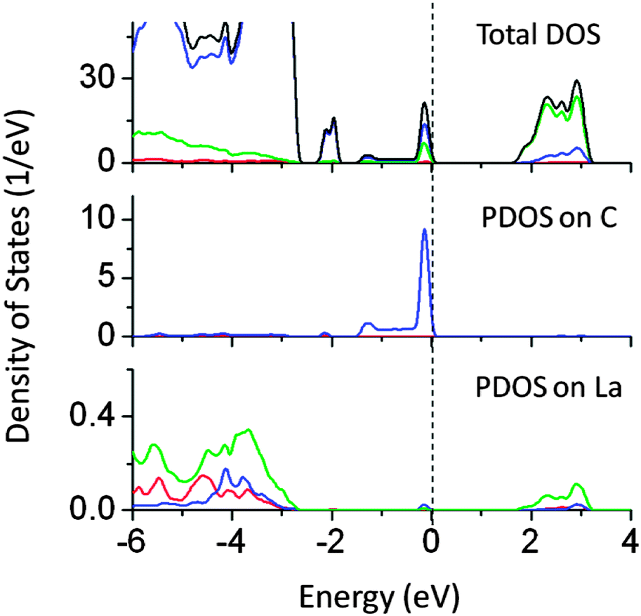 | ||
| Fig. 13 Total and partial density of states of La (at the Na site) and C (at the O site) co-doped NaTaO3, calculated using the hybrid (PBE0) functional, (red s; blue p; green d, black total). | ||
Although the individual dopants N and W do not reduce the band gap significantly, co-doping of W (at the Ta site) and N (at the O site) reduced the band gap by 1.2 eV. The narrowing is mainly contributed by N 2p states above the VBM, while W 6s induced energy states also appeared below the CBM as seen from PDOS plots in Fig. 14. It was seen that the extra energy states above VBM were also contributed by O 2p orbitals. Thus co-doping of N and W could be useful in inducing the visible light absorption in NaTaO3. Fig. 15 shows PDOS plots of N and I co-doped NaTaO3. Doping of N and I at the O site reduces the band gap by 0.65 eV by shifting the VBM upwards into the band gap. The newly created energy states are composed of N 2p and I 5p mixed states, while contributions from Ta 5d and O 2p were insignificant. This type of DOS indicates a weak bonding between Ta and I or Ta and N at the octahedral position. It is worth noting that individual dopants N and I reduce the band gap up to 0.9 eV, however, their cumulative effect on the band gap narrowing is significantly low.
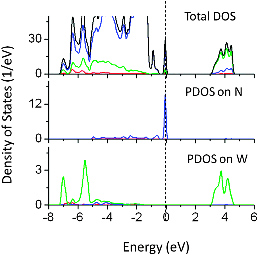 | ||
| Fig. 14 Total and partial density of states of W (at the Ta site) and N (at the O site) co-doped NaTaO3, calculated using the hybrid (PBE0) functional (red s; blue p; green d, black total). | ||
 | ||
| Fig. 15 Total and partial density of states of N (at the O site) and I (at the O site) co-doped NaTaO3, calculated using the hybrid (PBE0) functional (red s; blue p; green d, black total). | ||
We found that co-doping of Pb and I (at the Ta and O site respectively) also narrows the effective band gap by around 1.2 eV, allowing visible light absorption (Fig. 16). In this case, Pb 6s induced energy states appeared below the CBM lowering the effective CBM by 0.8 eV, while I 5s induced states appeared above the VBM, pushing the VB by around 0.4 eV. These energy orbitals are strongly hybridized with Ta 5d and O 2p.
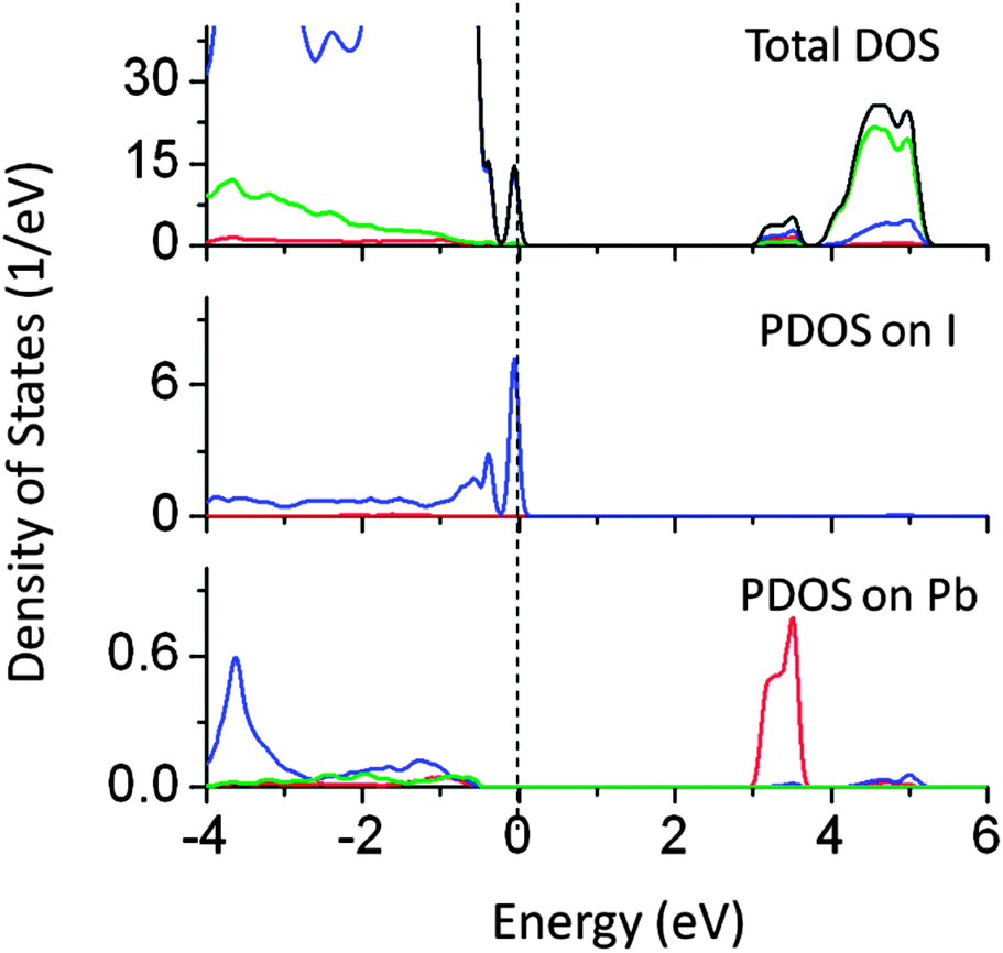 | ||
| Fig. 16 Total and partial density of states of Pb (at the Ta site) and I (at the O site) co-doped NaTaO3, calculated using the hybrid (PBE0) functional (red s; blue p; green d, black total). | ||
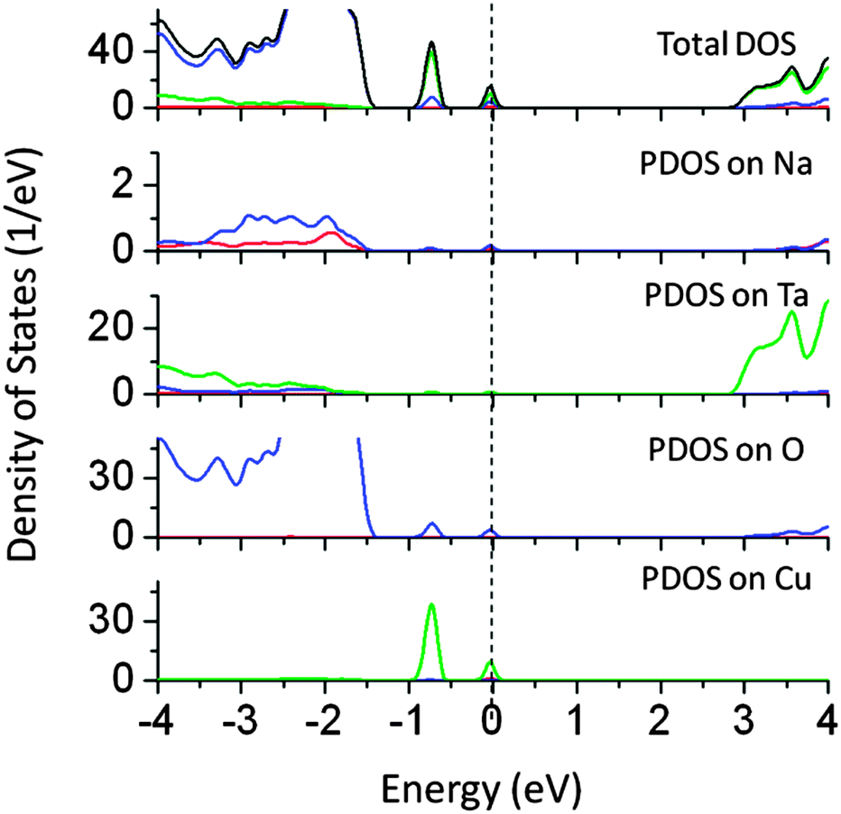
Finally, the effect of co-doping of Sn at the Ta site and Cu at the Na site was studied (PDOS in Fig. 17). PDOS plots showed a reduction of 2.5 eV in the effective band gap value. The mid-gap energy states are located at 1.3 eV above the VB in the band gap and 0.3 eV below the CBM. These states are mainly formed by Cu 3d orbitals. PDOS analysis showed that the contributions from Sn 5p were insignificant. As compared to mono-doping of Cu at the Na site, mid-gap states are spread over a narrow energy band and are completely occupied by the electrons. In all the co-doped cases, the impurity induced electronic states are completely filled and thus electronic excitation from filled states to CBM is possible. Such photoexcitation is favorable for photocatalytic reduction reactions.
 | ||
| Fig. 17 Total and partial density of states of Sn (at the Ta site) and Cu (at the Na site) co-doped NaTaO3, calculated using the hybrid (PBE0) functional (red s; blue p; green d, black total). | ||
3.7 Band diagrams and thermodynamic stability
The band edge potentials of the photocatalyst play a critical role in determining the thermodynamic possibility of the photoinduced reduction and oxidation reactions. It is known that hybrid functionals define the unoccupied band energies accurately and thus the present results provide a better understanding of the doped NaTaO3 systems. Along with photocatalytic water splitting, photocatalytic conversion of CO2 to hydrocarbons is of significant interest in the area of solar fuels, therefore the band edge potentials are estimated with respect to oxidation and reduction levels of water as well as reduction levels of CO2.Fig. 18 shows the band edge positions of co-doped NaTaO3 systems with respect to the water reduction and oxidation levels. Pristine NaTaO3 is known to have the CBM at −1.12 eV vs. the H2/H2O level.10 The CB and VB energies of doped systems are speculated based on the dopant induced energy states and the band gap values. All the doped systems have CB potentials enough for reduction of CO2 molecules to CH3OH and CH4 as well as photoreduction of protons i.e. H2O/H2. However, in the case of Pb–I co-doping, the potentials of the CB are significantly lowered to positive values and marginally enough for photoreduction of protons. The VB potentials of promising visible light absorbing systems such as Cu doping at the Na site, Cu doping at the Ta site, C doping at the O site, co-doping of W–N and Pb–I are enough for water photooxidation reaction. It is worth noting that effective VB potentials for C doping at the O site and Cu doping at the Ta site are close to the water oxidation level. Further, the effective VB potential of co-doped systems such as La–C and Sn–Cu are not suitable for water oxidation reaction. Thus, though these systems could absorb radiation in the visible region, they may not be suitable for photooxidation reaction of water. Nevertheless, these systems could be useful in other photocatalytic reactions such as degradation of organic compounds or photoreduction of CO2. The total energy calculations of the doped systems are presented in Fig. 19.
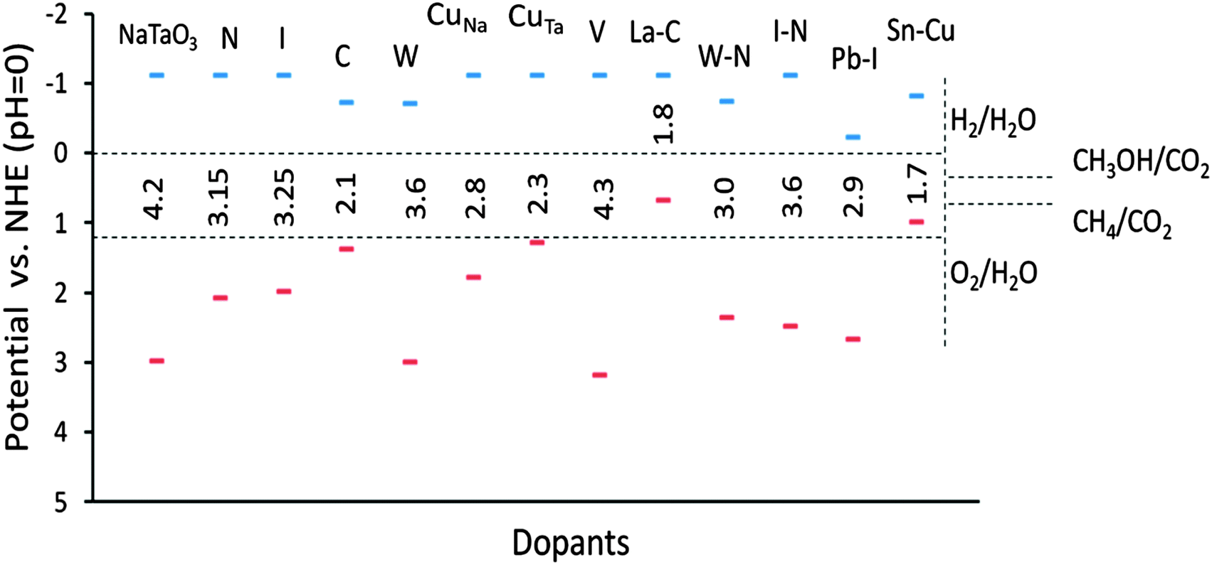 | ||
| Fig. 18 Estimated band edge potentials of doped and co-doped NaTaO3 systems. | ||
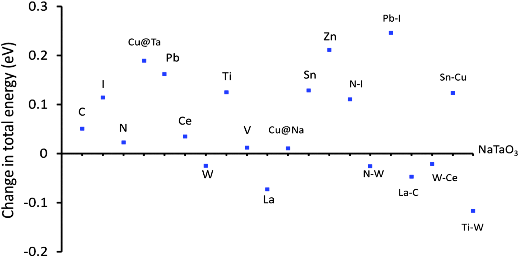 | ||
| Fig. 19 Changes in total energy of doped NaTaO3 with respect to pristine NaTaO3, energy difference in per atom energy. | ||
It is observed that certain dopants such as W at the Ta site, La at the Na site and certain co-dopant pairs such as La–C and W–Ce are thermodynamically favorable as compared to the other doped systems. These systems show lower total energy values as compared to the pristine NaTaO3 system. Further, the total energies of Cu doping (Ta site), I doping (O site), and co-doping of Pb–I have significantly higher values than NaTaO3, suggesting that these dopants have a lower stability in the lattice. It is noted that doping of Cu at the Na site is favored than doping of Cu at the Ta site. As doping of Cu at the Na site is likely to induce visible light absorption in NaTaO3 this system is promising and should be investigated further. The relative stability of the co-doped systems is assessed by calculating the defect pair binding energy according to eqn (2).
| ΔEb = ED1 + ED2 − ED1–D2 − Epure | (2) |
| # | Co-dopants | Band gap (eV) | Defect pair binding energy (eV) |
|---|---|---|---|
| 1 | N–I | 3.60 | 2.144 |
| 2 | N–W | 3.00 | 1.824 |
| 3 | La–C | 1.50 | 1.952 |
| 4 | W–Ce | 3.80 | 2.432 |
| 5 | Pb–I | 2.90 | 2.448 |
| 6 | Ti–W | 3.70 | 2.496 |
| 7 | Cu–Sn | 1.70 | 1.248 |
On the final note, we would like to mention that the models used in this study are ideal and do not represent the experimentally synthesized structures in a true manner. In particular, the models assume homogeneous doping in the single crystal and are limited to only one doping level. It is known that the doping levels and dopant distribution in the lattice affect the band structure significantly. However, the study of different doping levels is computationally expensive and could be done on the selected (promising) systems. Further, it is understood that the band gap and band edge potentials are basic thermodynamic criteria which decide the feasibility of the photocatalytic reactions. The photocatalytic activity strongly depends on several other factors. Factors such as electron–hole separation (exciton diffusion), charge transfer at the interface and point defects (particularly oxygen vacancy) affect the photocatalytic behavior. Therefore, the present study serves primarily as a guideline for the future work.
4. Conclusions
The effect of a wide range of dopants (anions: N, C and I, cations: Cu, V, W, Ti, Zn, In, Sn, Sb, La, and Ce) and co-dopants (N–W, N–I, Pb–I, La–C, Sn–Cu, W–Ti, and Ce–W) on the band structure of NaTaO3 was studied using DFT based calculations for visible light photocatalysis. The main conclusions drawn from this study are as follows.Electronic structure calculations show that dopants such as Cu (Ta site), Cu (Na site) and C (O site) induce visible light absorption in NaTaO3, narrowing its band gap below 3.0 eV. Dopants like I and N significantly reduce the effective band gap value, enough to absorb visible light.
Substitutional doping of cations such as Ti, V, Zn, In, Sn, Sb, La, and Ce does not alter the band gap significantly and thus does not help in visible light absorption.
Doping of C, Cu at the Na site, Cu at the Ta site and co-doping of N–W and Pb–I results in promising visible light photocatalysts with their band potentials favorable for water splitting reaction.
Although co-doping of La–C and Sn–Cu induces visible light absorption, hybrid calculations reveal that the band edge potentials of these systems are not suitable for the photocatalytic water splitting reactions.
Acknowledgements
Z.C. acknowledges the support from the National Research Foundation (NRF), Prime Minister's Office, Singapore under its Campus for Research Excellence and Technological Enterprise (CREATE) programme. S.C. would like to acknowledge the Carl Tryggers Stiftelse for Vetenskaplig Forskning (CTS) and Swedish Research Council (VR) for the financial support.References
- H. Tong, S. Ouyang, Y. Bi, N. Umezawa, M. Oshikiri and J. Ye, Adv. Mater., 2012, 24(2), 229–251 CrossRef CAS PubMed.
- A. Y. Shan, T. I. M. Ghazi and S. A. Rashid, Appl. Catal., A, 2010, 389(1–2), 1–8 CrossRef CAS PubMed.
- A. Di Paola, E. García-López, G. Marcì and L. Palmisano, J. Hazard. Mater., 2012, 211–212, 3–29 CrossRef CAS PubMed.
- H. A. Foster, I. B. Ditta, S. Varghese and A. Steele, Appl. Microbiol. Biotechnol., 2011, 90(6), 1847–1868 CrossRef CAS PubMed.
- A. Kudo and Y. Miseki, Chem. Soc. Rev., 2009, 38(1), 253–278 RSC.
- M. Kitano and M. Hara, J. Mater. Chem., 2010, 20(4), 627–641 RSC.
- H. Fu, S. Zhang, L. Zhang and Y. Zhu, Mater. Res. Bull., 2008, 43(4), 864–872 CrossRef CAS PubMed.
- P. D. Kanhere, J. Zheng and Z. Chen, J. Phys. Chem. C, 2011, 115(23), 11846–11853 CAS.
- L. Xu, C. Li, W. Shi, J. Guan and Z. Sun, J. Mol. Catal. A: Chem., 2012, 360, 42–47 CrossRef CAS PubMed.
- P. Kanhere, J. Zheng and Z. Chen, Int. J. Hydrogen Energy, 2012, 37(6), 4889–4896 CrossRef CAS PubMed.
- P. Kanhere, Y. Tang, J. Zheng and Z. Chen, J. Phys. Chem. Solids, 2013, 74(12), 1708–1713 CrossRef CAS PubMed.
- P. Kanhere, J. Nisar, Y. Tang, B. Pathak, R. Ahuja, J. Zheng and Z. Chen, J. Phys. Chem. C, 2012, 116(43), 22767–22773 CAS.
- Z. G. Yi and J. H. Ye, Appl. Phys. Lett., 2007, 91(25), 254108 CrossRef PubMed.
- Z. G. Yi and J. H. Ye, J. Appl. Phys., 2009, 106(7), 074910 CrossRef PubMed.
- M. Yang, X. Huang, S. Yan, Z. Li, T. Yu and Z. Zou, Mater. Chem. Phys., 2010, 121(3), 506–510 CrossRef CAS PubMed.
- A. Iwase, K. Saito and A. Kudo, Bull. Chem. Soc. Jpn., 2009, 82(4), 514–518 CrossRef CAS.
- W. H. Lin, C. Cheng, C. C. Hu and H. Teng, Appl. Phys. Lett., 2006, 89(21), 211904 CrossRef PubMed.
- Y. X. Wang, W. L. Zhong, C. L. Wang and P. L. Zhang, Solid State Commun., 2001, 120(4), 137–140 CrossRef CAS.
- E. Ece Eyi and S. Cabuk, Philos. Mag., 2010, 90(21), 2965–2976 CrossRef CAS.
- P. Han, X. Wang, Y. H. Zhao and C. Tang, Adv. Mater. Res., 2009, 79–82, 1245–1248 CrossRef CAS.
- X. Zhou, J. Shi and C. Li, J. Phys. Chem. C, 2011, 115(16), 8305–8311 CAS.
- M. D. Segall, P. J. D. Lindan, M. J. Probert, C. J. Pickard, P. J. Hasnip, S. J. Clark and M. C. Payne, J. Phys.: Condens. Matter, 2002, 14(11), 2717–2744 CrossRef CAS.
- J. P. Perdew, J. A. Chevary, S. H. Vosko, K. A. Jackson, M. R. Pederson, D. J. Singh and C. Fiolhais, Phys. Rev. B: Condens. Matter Mater. Phys., 1992, 46(11), 6671–6687 CrossRef CAS.
- M. Ahtee and C. N. W. Darlington, Acta Crystallogr., Sect. B: Struct. Crystallogr. Cryst. Chem., 1980, 36, 1007–1014 CrossRef.
- Y. Wang, T. Chena and Q. Mua, J. Mater. Chem., 2011, 21, 6006–6013 RSC.
- S. N. R. Inturi, T. Boningari, M. Suidan and P. G. Smirniotis, Appl. Catal., B, 2013, 144, 333–342 CrossRef PubMed.
- O. Palasyuk, A. Palasyuk and P. A. Maggard, Inorg. Chem., 2010, 49(22), 10571–10578 CrossRef CAS PubMed.
- R. Konta, H. Kato, H. Kobayashi and A. Kudo, Phys. Chem. Chem. Phys., 2003, 5(14), 3061–3065 RSC.
- M. Choi, F. Oba and I. Tanaka, Phys. Rev. B: Condens. Matter Mater. Phys., 2008, 78(1), 014115 CrossRef.
- B. Wang, P. Kanhere, Z. Chen, J. Nisar, B. Pathak and R. Ahuja, J. Phys. Chem. C, 2013, 117(44), 22518–22524 CAS.
- J. C. Yu, J. Yu, W. Ho, Z. Jiang and L. Zhang, Chem. Mater., 2002, 14(9), 3808–3816 CrossRef CAS.
- R. Asahi, T. Morikawa, T. Ohwaki, K. Aoki and Y. Taga, Science, 2001, 293(5528), 269–271 CrossRef CAS PubMed.
- J. Wang, S. Yin, M. Komatsu, Q. Zhang, F. Saito and T. Sato, Appl. Catal., B, 2004, 52(1), 11–21 CrossRef CAS PubMed.
- D. R. Liu, C. D. Wei, B. Xue, X. G. Zhang and Y. S. Jiang, J. Hazard. Mater., 2010, 182(1–3), 50–54 CrossRef CAS PubMed.
- X. Wang, G. Liu, Z. G. Chen, F. Li, G. Q. Lu and H. M. Cheng, Chem. Lett., 2009, 38(3), 214–215 CrossRef.
- P. Han, Y. Su, Y. Meng, S. Wang, Q. Jia and X. Wang, J. Nanosci. Nanotechnol., 2011, 11(11), 9600–9606 CrossRef CAS PubMed.
- Y. Gai, J. Li, S. S. Li, J. B. Xia and S. H. Wei, Phys. Rev. Lett., 2009, 102(3), 036402 CrossRef.
- I. S. Cho, C. H. Lee, Y. Feng, M. Logar, P. M. Rao, L. Cai, D. R. Kim, R. Sinclair and X. Zheng, Nat. Commun., 2013, 4, 1723 CrossRef PubMed.
| This journal is © the Owner Societies 2014 |