Evidence of short-range electron transfer of a redox enzyme on graphene oxide electrodes†
Received
29th January 2014
, Accepted 13th March 2014
First published on 13th March 2014
Abstract
Direct electron transfer (DET) between redox enzymes and electrode surfaces is of growing interest and an important strategy in the development of biofuel cells and biosensors. Among the nanomaterials utilized at electrode/enzyme interfaces to enhance the electronic communication, graphene oxide (GO) has been identified as a highly promising candidate. It is postulated that GO layers decrease the distance between the flavin cofactor (FAD/FADH2) of the glucose oxidase enzyme (GOx) and the electrode surface, though experimental evidence concerning the distance dependence of the rate constant for heterogeneous electron-transfer (khet) has not yet been observed. In this work, we report the experimentally observed DET of the GOx enzyme adsorbed on flexible carbon fiber (FCF) electrodes modified with GO (FCF-GO), where the khet between GO and electroactive GOx has been measured at a structurally well-defined interface. The curves obtained from the Marcus theory were used to obtain khet, by using the model proposed by Chidsey. In agreement with experimental data, this model proved to be useful to systematically probe the dependence of electron transfer rates on distance, in order to provide an empirical basis to understand the origin of interfacial DET between GO and GOx. We also demonstrate that the presence of GO at the enzyme/electrode interface diminishes the activation energy by decreasing the distance between the electrode surface and FAD/FADH2.
Introduction
Direct electron transfer (DET) between redox enzymes and electrode surfaces is of great interest because of their potential importance in the enzyme kinetics and in the development of new generations of biosensors and biofuel cells that require rapid, well-defined electron transfer. For instance, several molecular models to explain the DET between the glucose oxidase (GOx) enzyme and electrode surfaces have been proposed.1,2 GOx is a structurally rigid glycoprotein of 160 kDa with a hydrodynamic radius of 43 Å, consisting of two identical polypeptide chains, each containing a flavin adenine dinucleotide (FAD/FADH2) center.3,4 Following the first reports on DET with a redox active protein in 1977,5,6 several authors have reported the DET of GOx in different electrode configurations.7,8 The effect of protein environments on the facilitation of DET is a fundamental problem in enzyme catalysis with implications on a wide range of materials from bioanodes in biofuel cells9 to third generation biosensor design.10 As the FAD redox active center of GOx is deeply buried in a glycoprotein shell, electrochemical DET from the FAD of GOx to an electrode surface is very slow. The elucidation of factors that hinder electron transfer is central to technological improvements. In the investigation of such factors, Heller and co-workers reported1,7 that the distance dependence of the electron-transfer rate is central to understanding why some experimental conditions can lead to DET; electron transfer rates between the enzyme and the electrode surface decay exponentially with the distance. It is therefore unsurprising—given the macromolecular size of enzymes—that GOx does not efficiently communicate with electrode surfaces; natural systems often need to transfer electrons with high directional specificity over distances greater than 14 Å.33 In order to enhance the electronic communication in such processes, one line of enquiry has been the incorporation of materials on electrode surfaces which facilitate better electron transfer.
DET has recently been reported in which nanomaterials such as nanoparticles,11 nanotubes,12 graphene oxide (GO)13 and reduced graphene oxide14 (rGO) have been incorporated on electrodes. Although there is no experimental data to rationalize the occurrence of DET, it is postulated that the nanomaterials enhance the electronic communication. To this end, GO is a promising material in the promotion of DET, due to the single layers of carbon atoms that can organize themselves in a closely packed two-dimensional honeycomb lattice on the electrode surface,15 leading to a high surface activity area and fast rates of DET. However, no evidence exists at the molecular level as to why an interface composed of GO between the electrode and the GOx enzyme promotes fast DET. Few well-defined experimental systems are available to probe fundamental issues such as the dependence of interfacial electron transfer rates on the reaction free energy, the electron-transfer distance, or the molecular structure of the GOx at the interface. This can be explained because, unlike other redox systems (e.g. cytochrome c), it is very difficult to attach the FAD cofactor of GOx to the electrode surface without altering its tertiary structure, thus making it difficult to assess the value of the heterogeneous FAD electron transfer constants as a function of the electrode distance.
In this work, the rate constant of the electron transfer reaction between a flexible carbon fiber (FCF) electrode modified with GO (FCF-GO) and electroactive GOx enzymes has been measured at a structurally well-defined interface at different temperatures. The curves obtained from the Marcus theory16–18 were used in order to calculate heterogeneous electron transfer constants (khet), using the model proposed by Chidsey.19 The latter model proved to be useful to systematically probe the dependence of electron transfer rates on distance, in order to provide an empirical basis for understanding the origin of interfacial DET. Through electrochemical studies, we demonstrate that the presence of GO at the enzyme/electrode interface decreases the activation energy by shortening the distance between the electrode surface and the FAD/FADH2 redox couple.
Experimental details
Graphene-oxide formation (in situ) on FCF electrodes
It is well known that exfoliated graphene oxide or GO can form well-dispersed aqueous colloids.20 Stankovich and co-workers21 reported that solution-based routes involve the chemical oxidation of graphite to hydrophilic graphene oxide, which can be readily exfoliated as individual GO sheets by ultrasonication in water. An alternative methodology was sought to obtain graphene-oxide directly adsorbed on FCFs (FCF-GO); we used (with modifications) the chemical route proposed by Kovtyukhova and co-workers22 for FCF exfoliation. Carbon fibers were extracted from a carbon cloth (CCS 200). The FCFs (0.5 g) were placed in H2SO4–KMnO4 (120 mL), which was prepared from KMnO4 (464 mg) dissolved in H2SO4 (1 M). The FCFs were kept in an ultrasound bath for 3 hours, then washed with HCl (to remove MnO2) and distilled water.
Fibers modified with GO were characterized by infrared (IR) spectroscopy, Raman spectroscopy, field emission scanning electron microscopy (FEG-SEM), energy dispersive X-Ray spectroscopy (EDX) and X-ray diffraction (XRD). IR analyses of the FCFs were performed by Fourier-transform infrared spectroscopy (FTIR). The FCFs were placed directly on a ZnSe diamond during the acquisition of the spectra. The experiments were carried out in ATR/absorption mode, using a Varian C640 FT-IR spectrophotometer. Raman spectra were recorded on a Jobin Yvon T-64000 spectrometer, with laser alignment at 532.14 nm; a unique fiber was isolated using an optical microscope and placed on a glass substrate in order to focus the beam. FEG-SEM (JMS-6701F, JEOL) images were obtained in order to analyze the morphological characteristics of the fibers before and after the fiber exfoliation process. Several fibers were placed on a double-sided carbon tape and subsequently placed in the sample holder.
FCF-GOx and FCF-GO-GOx bioelectrodes
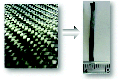
The FCF-GOx and FCF-GO-GOx bioelectrodes were prepared via the physical adsorption23,24 of the enzyme. An area of the fiber (0.2 cm2) was treated with epoxy resin. After drying the resin, the FCF was placed in the GOx solution (10 mg mL−1 in sodium phosphate buffer, pH 7.02) for 24 hours at 4 °C. The fiber was washed with buffer to remove non-adsorbed enzymes, and vacuum dried. Nafion solution (5%, 20 μL) was dropped onto the fiber containing the adsorbed GOx, affording the FCF-GO-GOx bioelectrode. The same procedure was performed for the untreated fiber, furnishing the FCF-GOx bioelectrode. Fig. 1 shows a photograph of the carbon cloth (left) and of a fiber (right) before chemical exfoliation. The schemes in Fig. S1a and b (see the ESI†) depict the chemical exfoliation and the enzyme immobilization processes, respectively.
 |
| | Fig. 1 Carbon cloth (left) and an extracted flexible carbon fiber (FCF). | |
FCF-GO-GOx non-catalytic electrochemistry
To investigate the redox behavior and kinetic properties of the FCF-GOx and FCF-GO-GOx bioelectrodes, a conventional system of three electrodes was used: Ag/AgClsat as the reference electrode, platinum as the counter electrode and the synthesized bioelectrodes as the working electrodes. All analyses were performed using a μAutolab Type III galvanostat/potentiostat apparatus.
Temperature dependence experiments
Electrochemical measurements to obtain the direct electron transfer of GOx were performed using a three electrode system comprising a flexible carbon fiber after chemical treatment (FCF-GO) as the working electrode, platinum as the counter electrode, and a saturated Ag/AgCl electrode as the reference electrode. Phosphate buffer solution (0.1 mol L−1, pH 7.0) was used as the electrolyte, which was purged with argon for at least 30 minutes prior to the recording of voltammograms under an argon atmosphere. The temperature of the electrolyte was varied by using a thermostatic bath (GE-MultiTemp IV Thermostatic Circulator, 0.01 °C resolution). The internal temperature of the electrochemical cell was also monitored using a thermometer. The study of the DET of GOx at different temperatures was carried out between 5.0 °C and 37.0 °C at pH 7.0.
Influence of pH on DET
To study the influence of pH on DET, the electrochemical measurements were performed using a three electrode system as described above. The study was carried out at various pH values between 5.5 and 8.0 using a phosphate buffer solution (0.1 mol L−1) as the electrolyte.
Biocatalytic properties of FCF-GO-GOx
The catalytic activity of GOx in the FCF-GO-GOx bioelectrode was tested by polarization curves and chronoamperometry experiments at different glucose concentrations. The glucose solution (1.0 mol L−1) was prepared and stored overnight. A potential of −0.3 V was applied in the chronoamperometry experiments. All experiments were performed under anaerobic conditions; oxygen was removed from the electrolyte by bubbling N2 gas through the solution for 15 minutes.
Numerical modeling
To interpret the electron-transfer behavior of the bioelectrodes, the Marcus theory was applied to the interfacial electron transfer between an electrode and an adsorbed redox couple. We adopted the approach of Chidsey19 to calculate the electrochemical rate constants as a function of potential. The Butler–Volmer model25 was also used to calculate the kinetic parameters. All calculations in this study were performed using the Matlab® software.
Results and discussion
Graphene oxide-modified FCF
Fig. 2 shows high-resolution FEG-SEM images of the FCF (a and b) and FCF-GO (c–e) at different magnifications.
 |
| | Fig. 2 Field emission-scanning electron microscope (FEG-SEM) images of the FCF at different magnifications: untreated (a and b) and graphene oxide (GO)-modified fibers (FCF-GO) (c–e). | |
The FCF has a diameter of 6.5 μm and homogeneous morphology, characteristic of FCFs in general. Following treatment with H2SO4–KMnO4 solution, the morphology of the fiber surfaces change considerably. In the images shown in Fig. 2c–e, there are various aggregates randomly affixed that suggest graphene is adsorbed in a disorderly fashion. In comparison to other studies reported in the literature,21,26 GO has a structure similar to that observed in the images. To confirm the presence of GO, the FCFs were characterized by Raman spectroscopy.
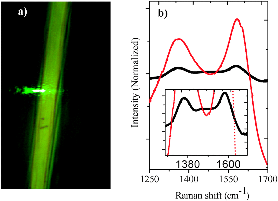
Fig. 3a shows an optical micrograph of the green laser focalization on the FCF surface. Fig. 3b shows the Raman spectra of the untreated FCF (black line) and FCF-GO (red line). Both spectra show two bands at about 1360 cm−1 (D band), assigned to the scattering of the graphite edges,27 and at 1580 cm−1 (G band), assigned to the first order E2g mode28 of the C–C bond. Graphite materials usually exhibit two Raman bands in the active spectrum near 1575 and 1355 cm−1.29 However, small shifts in this region and changes in the band intensities indicate changes in bond lengths and angles.30 The maximum intensity D (ID) and G (IG) bands of the FCF are exactly identical (black line). However, it is observed that the intensity of the FCF-GO D and G bands (red line) are different. The increase in the G band is caused by the presence of graphene oxide.30 This increase could also be attributed to a greater number of defects in the hexagonal carbon structure that constitutes the GO, as proposed by Ramesha and co-workers.31
 |
| | Fig. 3 (a) Optical microscope images showing the focusing of a green laser (532 nm) onto the surface of a FCF using a MicroRaman spectroscope. (b) The Raman spectrum of the FCF (black line) and FCF-GO (red line). Inset: the magnified spectrum showing the lower intensity Raman scattering of FCFs compared to FCFs treated with acid solution. | |
Table 1 lists values presented in the literature21,31,32 reported for the D and G bands in GO. According to the literature, the smaller the value of the ratio of D and G bands (ID/IG), the greater the number of defects in the hexagonal carbon structure. This indicates the formation of graphene oxide within the sheets, as can be seen in the FEG-SEM images in Fig. 2.
Table 1 Values of D and G bands and ID/IG ratio in GO
| D |
G |
I
D/IG |
Ref. |
| 1363 |
1594 |
0.85 |
21
|
| 1350 |
1610 |
0.83 |
31
|
| 1350 |
1581 |
0.85 |
32
|
| 1360 |
1580 |
0.86 |
This work |
Infrared spectroscopy was performed to confirm the presence of oxygenated groups in the structure of the GO. Fig. 4a shows the spectra of the untreated FCF (black line) and the FCF-GO (red line). In the spectrum of the FCF, there are two bands at 2849 and 2919 cm−1, assigned to symmetrical stretching vibration modes of the C–H and C–C bonds, respectively. Also in this spectrum, there are several bands between 1700 and 1500 cm−1, which can be attributed to the angular deformation modes of CH3 and CH2 groups. However, significant spectroscopic differences can be seen for the FCF-GO spectrum (red line). This spectrum shows a band at 3396 cm−1, attributed to the stretching vibration mode of carboxylic acid O–H bonds. The bands at 2849 and 2919 cm−1 are assigned to the symmetrical stretching vibration modes of the C–H and C–C bonds respectively. The bands at 1643, 1386 and 1025 cm−1 are assigned to C![[double bond, length as m-dash]](https://www.rsc.org/images/entities/char_e001.gif) O bond stretching, O–H bond deformation, and C–O bond stretching of carboxylic acids, respectively.34–36
O bond stretching, O–H bond deformation, and C–O bond stretching of carboxylic acids, respectively.34–36
 |
| | Fig. 4 (a) Fourier transform infrared (FTIR) spectrum of the untreated FCF (black line) and FCF-GO (red line) electrodes. (b) A magnified view of the FTIR spectrum of (a) showing the appearance of CO stretching bands characteristic of carboxylic acid functional groups. (c) Energy dispersive X-ray spectroscope (EDX) image showing the chemical mapping of the FCF-GO with trace elemental carbon in yellow color and (d) with trace elemental oxygen in blue color. | |
It is known that the chemical structure of GO varies between reports, depending on the synthetic procedure.32 There are several possible models proposed in the literature15 based on experimental data (e.g. NMR, XRD, IR, and X-ray photoelectron spectroscopy (XPS)) to assign the chemical composition of the GO. In this instance, the spectroscopic behavior of the FCF-GO indicates that the GO is functionalized with carboxyl groups, as can be seen in Fig. 4b, in which the stretching mode of CO appears at a higher intensity in the FCF-GO. Corroborating the previous results, the presence of hydrophilic groups in the GO structure causes changes in X-ray diffraction (XRD). Fig. S3 (ESI†) shows the diffractograms of the FCF (black line) and the FCF-GO (red line). Both spectra show two well defined peaks, one at 2θ = 11.7° corresponding to the (001) reflection, and another at around 2θ = 25.0° corresponding to the (002) reflection.37 The intensity of the (001) peak of the FCF-GO is greater when compared to the intensity of the FCF. Another finding is the shift of the (002) peak from 24.1° to 25.1°, as can be seen in the inset of Fig. S3 (ESI†). In addition, the broader (002) peak is usually correlated to an interlayer spacing between the GO sheets,38 probably due to agglomerates seen in the FEG-SEM images and the presence of –COOH groups.39 The Raman, IR and XRD spectra are consistent with the chemical mapping images realized by EDX, which shows the presence of elemental carbon (Fig. 4c) and oxygen (Fig. 4d).40 It is also possible that epoxide and alcohol groups are present, as suggested in the model proposed by Dreyer and co-workers.41
Direct electron transfer of GOx on FCF-GO
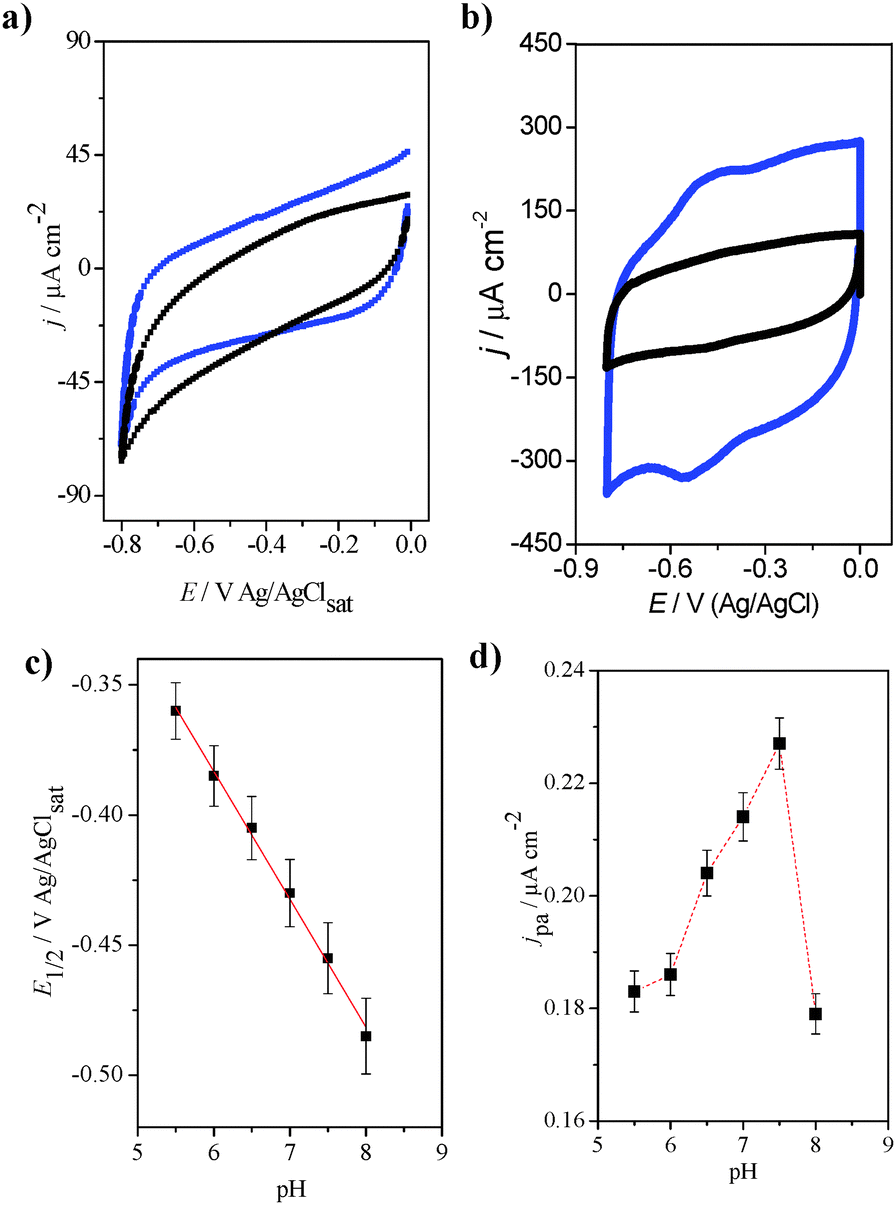
Before investigating the redox properties of the GOx immobilized on the fibers, the electrochemical behaviors of the carbon fibers before and after the formation of GO were evaluated. Fig. 5a shows cyclic voltammograms for both the FCF (black line) and the FCF-GO (blue line) in the potential region between 0.0 and −0.8 V vs. Ag/AgCl. Both the FCF and FCF-GO electrodes exhibit similar electrochemical behavior in sodium phosphate buffer solution at pH 7.0, where there are no Faradaic processes. Only a small increase in the capacitive currents for the FCF-GO electrode is observed. This increase in capacitive current can be attributed to an increase in roughness of the fiber's surface, due to the presence of GO, as seen in the FEG-SEM images (Fig. 2). After GOx immobilization on the FCF (or FCF-GOx) surface, two redox processes are observed, as seen in the voltammogram in Fig. 5b (black line). However, when GOx is immobilized on FCF-GO (FCF-GO-GOx), a similar redox process appears both sharper and shifted to a more negative potential (blue line, Fig. 5b). The formal potential (E°) for both the FCF-GOx and FCF-GO-GOx bioelectrodes can be calculated using eqn (1).| |  | (1) |
where Epa and Epc are the peak potentials for the anodic and cathodic processes, respectively.
 |
| | Fig. 5 Cyclic voltammograms of (a) FCF (black line) and FCF-GO (blue line). Scan rate: 30 mV s−1. (b) Cyclic voltammograms of FCF-GOx (black line) and FCF-GO-GOx (blue line). Scan rate: 100 mV s−1. Electrolyte support: sodium phosphate buffer, pH 7.0. (c) Plot of dependence of half-wave potential as a function of pH. (d) Plot of dependence of the current density of the oxidation peak as a function of pH. | |
Applying eqn (1) we obtained −0.43 V for the FCF-GOx electrode, and −0.55 V for the FCF-GO-GOx electrode. Both values are very close to the theoretical formal potential (E°′) of the FAD of GOx vs. Ag/AgCl at pH 7.0.37–39 The value of the potential separation between the anodic and cathodic peaks (ΔE) was 60 and 50 mV for FCF-GOx and FCF-GO-GOx, respectively. Values below 60 mV may indicate a reversible process and a fast charge exchange42 for the reduction/oxidation of the FAD/FADH2 cofactor, as described in eqn (2).
| | | FAD + 2e− + 2H+ ⇆ FADH2 | (2) |
Furthermore, the bioelectrodes are very stable; anodic and cathodic peak currents do not change over 20 consecutive voltammetric cycles (see Fig. S4 in ESI†). The pH dependence of the steady currents of the GOx oxidation/reduction was determined by monitoring experiments over the entire range of pH from 5.5 to 8.0. In all pH ranges, a reversible process was observed, with the same modulus values for the oxidation and reduction currents. The difference between the peak potentials corresponded to 0.0592/n, where n is the number of electrons involved in the semi-reaction. Thus, the average value obtained from the difference between the peak potentials was 0.023 ± 0.008, close to the theoretical reversible two-electron reaction (0.0295). The slope of the graph E1/2vs. pH (Fig. 5c) was −49 mV per pH, close to the theoretical value (−59 mV per pH) for reversible processes in the reaction of two protons with two electrons. From the graphs in Fig. 5d, it was concluded that the optimum pH for DET is between 7.0 and 7.5. At pH 5.5 and 6.0, the redox process appears subtle enough to offset less negative potentials (see Fig. S5 in ESI†). As the pH increases to 6.5, the process begins to appear more defined, although it is still shifted. For pH values of 7.0 and 7.5, the redox process is more clearly defined and the peak currents obtained are larger. At pH 8.0, the currents obtained are lower and the peak does not appear well-defined as compared to previous pH values. Thus, for the further experiments, the sodium phosphate electrolyte was maintained at pH 7.0.
DET temperature dependence
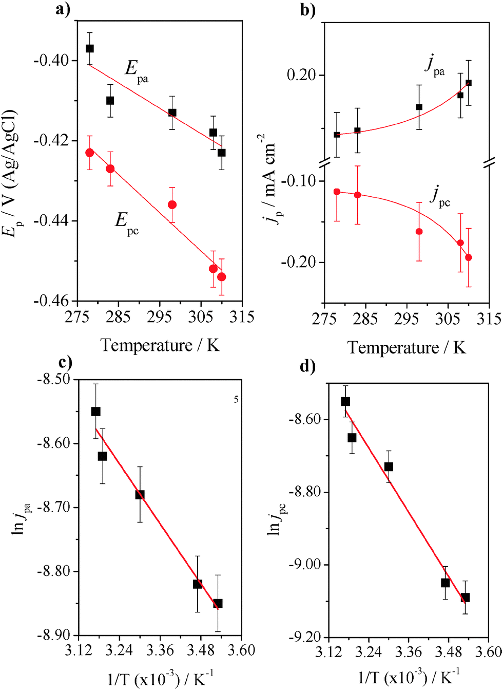
The temperature dependence of the electron transfer was investigated by varying the temperature of the electrolyte from 278 to 310 K (see Fig. S6 in ESI†). In this experiment, it is important to consider that the thermal denaturation of GOx causes dissociation of the flavin cofactor. The properties of the thermally denatured protein indicate that thermally denatured GOx adopts a compact structure, a form of molten globule-like apoenzyme.43 The FCF-GO-GOx electrode was used in the experiments and cyclic voltammograms were recorded at 50 mV s−1 at five temperatures (278, 283, 298, 308 and 310 K). There was no significant change in the voltammetric profile when the temperature was changed from 278 K to 283 K, though changes were more pronounced when the temperature was increased to higher values (298 K), with a smaller increase at 310 K. The increase in temperature promotes an increase in both anodic and cathodic peak currents with a shift of potentials to more negative values. Fig. 6a shows the decrease in Epa (black dots) and Epc (red dots) with increasing temperature and Fig. 6b shows the increase in current density peaks, jpa (black dots) and jpc (red dots), both in the temperature range described previously.
 |
| | Fig. 6 Plots of Ep (a) and jp (b) of FCF-GO-GOx as a function of the temperature (K). Scan rate: 50 mV s−1. Electrolyte: sodium phosphate buffer 7.02. Plots of ln![[thin space (1/6-em)]](https://www.rsc.org/images/entities/char_2009.gif) jpa (c) and lnjpc (d) of immobilized GOx as a function of the reciprocal of temperature for Ea calculation. The experiments were obtained in triplicate using three different electrodes, and the variability of the data was measured by considering the standard deviation and errors calculated from t-tests with 95% confidence interval. The means were plotted with error bars. jpa (c) and lnjpc (d) of immobilized GOx as a function of the reciprocal of temperature for Ea calculation. The experiments were obtained in triplicate using three different electrodes, and the variability of the data was measured by considering the standard deviation and errors calculated from t-tests with 95% confidence interval. The means were plotted with error bars. | |
The experiments were repeated three times using three different electrodes, and the variability of the data was measured by considering the standard deviation and errors calculated from t-tests with a 95% confidence interval. A straight line was observed (least-squares correlation coefficient = 0.967 for the oxidation process and 0.969 for the reduction process). The presence of two redox processes is clear, as demonstrated by EOx = −0.40V and ERed = −0.43V, as expected for DET of the FAD cofactor of the GOx enzyme.7,8 The activation energy for the GOx enzyme was calculated using the Lumry–Eyring model.44,45 Although the model assumes a transition state from a normal enzyme state to a denatured state, the temperature dependence of the electron transfer kinetics (k0) was investigated away from the denaturation temperature of GOx in order to obtain more accurate information about DET in the same temperature range.
The relationship between the rate constant (k0) and the electron transfer can be described by eqn (3).46
where
n is the number of transferred electrons,
F is the Faradaic constant,
A is the surface area of the working electrode, and [E] is the concentration of immobilized GOx in the equilibrium. In this case,
n,
F,
A, and [E] are constants since all experiments were obtained with the same working FCF-GO-GOx electrode. Thus,
imax is directly proportional to
k0, allowing
imax (and consequently the current density,
jmax) to be used in the Arrhenius plot. Some interesting studies have reported the relationship between
Ea, the transfer coefficient (
α), and the hidden heat of electrode process (
q).
25 For instance, we use the simplest concept of Arrhenius (
k0 =
A exp(−
Ea/
RT)), where
Ea is the activation energy,
A is the pre-exponential factor,
R is the molar gas constant (8.314 kJ mol
−1 K
−1),
T is the temperature in K, and
k0 is the heterogeneous charge transfer reaction
16–18 in order to estimate the energy of activation (
Ea) for GOx.
Fig. 6c and d show the plots of ln
jpa and ln
jpc, respectively,
vs. the reciprocal of temperature (1/
T). The apparent
Ea value was obtained as 280 kJ mol
−1 with an apparent transition temperature of 55.8 ± 1.2 °C (328.95 K).
47 The values of
Ea calculated from the linear range of ln
jmaxvs. 1/
T for anodic and cathodic peaks were 6.49 kJ mol
−1 and 12.26 kJ mol
−1, respectively.
The standard potential E0 is an important value as it is related to the standard free energy of the reaction ΔG0T,p and to the equilibrium constant K according to eqn (4):48
| | | −nFE0 = ΔG0T,p = −RT lnK | (4) |
We can therefore use the above relationship to calculate the standard free energy of the direct electron transfer of GOx. It is known that the number of electrons n in the redox process is two, F is the Faraday constant, and E0 is −0.55 V; ΔG0 for the DET of GOx is therefore −106.1 kJ mol−1. Table 2 shows the kinetic and thermodynamic parameters for the FCF-GO-GOx electrode configuration.
Table 2 Kinetic and thermodynamic parameters of FCF-GO-GOx
|
E
0
|
−0.550 V |
| ΔE |
0.023 ± 0.008 |
|
E
a
|
6.49 kJ mol−1 (oxidation process)
12.26 kJ mol−1 (reduction process)
|
| ΔG0 |
−106.1 kJ mol−1 |
Bioelectrocatalytic properties
To confirm that the process of enzymatic immobilization did not damage the catalytic performance of GOx toward the oxidation of glucose, biocatalytic tests were performed.
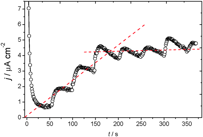
Fig. 7 shows a chronoamperometry experiment at −0.3 V of applied potential for 400 s. This potential was chosen because it is the value at which the current reaches a quasi-steady state for the oxidation of glucose. Accordingly, Fig. 7 shows the chronoamperometric response of FCF-GO-GOx in the presence of successive additions of glucose. Each addition corresponds to an addition of 100 mL of glucose at a concentration of 0.5 mol L−1. The time required to achieve the quasi-steady state current shortly after the addition is 6 seconds, indicating a rapid response.49–51 The increase in glucose concentration rapidly promotes oxidation in the chain, reaching saturation level at high concentrations, as expected by Michaelis–Menten behavior (see Fig. S7 in ESI†). Such behavior indicates that glucose is easily oxidized at low concentrations by the FCF-GO-GOx bioelectrode and implies that FAD is active within the protein structure of GOx.
 |
| | Fig. 7 Chronoamperometry of the FCF-GO-GOx bioelectrode in the presence of successive additions of glucose (total glucose concentration of 1 mmol L−1, 2 mmol L−1, 3 mmol L−1, 4 mmol L−1, 5 mmol L−1, 6 mmol L−1, and 7 mmol L−1, respectively) at −0.3 V of applied potential. | |
Using Marcus theory for DET
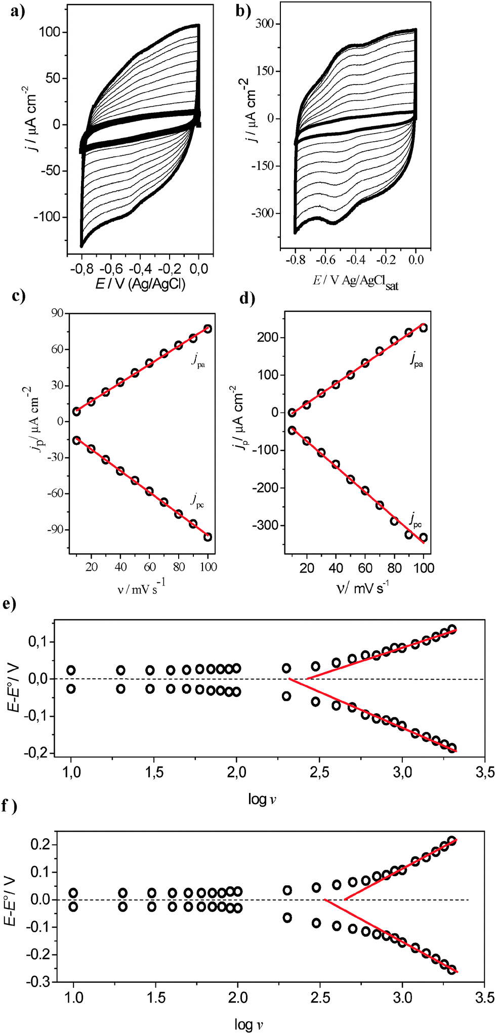
To investigate the direct electron transfer at the electrode/enzyme interface, several voltammetric cycles at different scan rates for both the FCF-GOx and FCF-GO-GOx systems were carried out, as shown in Fig. 8a and b. Increasing the scan rate promotes increased current densities of the anodic and cathodic peaks. Thus, upon constructing graphs of the current density dependence as a function of the scan rate (υ) two straight lines are obtained (Fig. 8c and d). This behavior indicates two phenomena: first, the electrochemical processes are governed by charge transfer at the GOx/FCF interface, and secondly, the enzyme is strongly adsorbed on the carbon electrode surface. The study of heterogeneous electron transfer rates for FCF-GOx and FCF-GO-GOx bioelectrodes was explored by varying the scan rate from 10 to 2000 mV s−1 (see Fig. S8a and b in ESI†). It is clearly observed that the FAD redox processes remain sharp up to 2000 mV s−1 for the FCF-GO-GOx bioelectrode. The linear relationship between the scan rate and the current density of the anodic and cathodic peaks also remains for both the bioelectrodes (see Fig. S8c and d in ESI†). In Fig. 8e and f, the plotted lines represent calculated rate constants for different models of electron-transfer (ET) kinetics. The dash-dot curves in Fig. 8e and f are the plots of the rate constants, as predicted by the Butler–Volmer (BV) formalism:25| | | kBVred = k0 exp(−αF(E − E0)/RT) | (5) |
| | | kBVoxi = k0 exp((1 − α)F(E − E0)/RT) | (6) |
where k0 is the rate constant at zero overpotential and α is the electron transfer coefficient, which represents the degree of symmetry between the reduction and oxidation rate constants (α = 1/2 for the symmetrical case). By using Laviron's method25 (which is based on the BV theory), α can be determined from the slope of the straight lines of anodic (ka) and cathodic (kc) peak potentials versus log(υ) (Fig. 8e and f) according to log(ka/kc) = log[α/(1 − α)] or also from logυa/υc = log[α/(1 − α)] and k0 can be calculated using eqn (7):| |  | (7) |
The α and k0 values were estimated at 0.56 and 9.08 s−1 for FCF-GOx and 0.57 and 15.04 s−1 for FCF-GO-GOx, respectively. Although the Butler–Volmer formalism is more empirical and more commonly used than the Marcus theory,16–18 in this model, the activation energies for both the cathodic and anodic rates are assumed to be a linear function of the overpotential and it is not considered as the influence of the reorganization energy. Consequently, the classical BV equation does not represent accurate rate constant values.
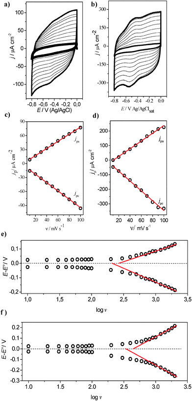 |
| | Fig. 8 Cyclic voltammograms of (a) FCF-GOx and (b) FCF-GO-GOx at different scan rates: 10, 20, 30, 40, 50, 60, 70, 80, 90 and 100 mV s−1. (c) and (d) the dependence of (jpa) and cathodic (jpc) peaks as a function of scan rate. Electrolyte support: sodium phosphate buffer, pH 7.0. Plots of variation of anodic and cathodic peak overpotential (E − E0) as a function of logυ for electrode configuration (e) FFC-GO-GOx and (f) FCF-GO-GOx. | |
The Marcus theory describes the homogeneous electron transfer between two chemical species as a function of the nuclear configuration of initial and final species16–18 using Gibbs energy diagrams.48 The nuclear configuration is represented by two identical parabolas, as shown in Fig. 9a.
 |
| | Fig. 9 (a) Marcus energy diagrams showing the initial (GOx-FADH2) and final states (GOx-FAD) of electron transfer (ET). Plot of the measured decay rate constants (squares) at 25 °C and calculated rate constants from eqn (8) with: λ = 0.2 eV (dots), λ = 0.38 eV (solid) and λ = 0.5 eV (dashed), and from eqn (5) and (6) (dash-dot) with k0 = 9.08 s−1, α = 0.56 for FCF-GOx and k0 = 15.04 s−1, α = 0.57 for (b) FCF-GOx and (c) FCF-GO-GOx. (d) Plot of the measured decay rate constants (square) at 25 °C from 25 eV to 0.2 eV. (e) Oxidative ET rate constant (kox) as a function of overpotential for FCF-GOx (k0 = 9.08 s−1, α = 0.56) and FCF-GO-GOx (k0 = 15.04 s−1, α = 0.57) according to Marcus theory of interfacial ET (eqn (8) with λ = 0.38 eV). | |
The initial state GOx-FADH2 (black dots) and final state GOx-FAD (red dots) are represented by two identical parabolas with the respective initial (G1) and final (G2) Gibbs energies. The intercept point between the two parabolas and the minimum energy state G1 is represented by Ea, with the difference between the two minimum energy states (G1 and G2) represented by ΔG0. In this manner, this study adopted the approach of Chidsey19 to calculate electrochemical rate constants as a function of potential. For electron transfer between an electrode and an adsorbed redox couple, Chidsey19 derived a relationship between ET rate constants (kred/oxi) and overpotential (E − E0) by integrating the Marcus equation (eqn (8)), which describes the ET rate using the Fermi–Dirac distribution, since electron transfer can occur to or from any Fermi level in the electrode:
| |  | (8) |
where
λ is the reorganization energy in eV (the energy required to reorient all atoms from the equilibrium state to the product state).
kmax is the maximum electron-transfer rate constant at high overpotential, and is given by
eqn (9):
| |  | (9) |
where
V0 represents the degree of electronic coupling,
r is the distance between the donor and the acceptor (in Å) and
β is the decay coefficient (in Å
−1). Rate constants can be numerically evaluated from
eqn (6) using the method described by Heering and co-workers.
52 This method was used to calculate the plots of
kred +
koxi against
E −
E0 in
Fig. 9b and c for different values of reorganization energy (lines). The curve with
λ = 0.38 eV was the best fit; this
λ value was used to generate the curves for FCF-GOx and FCF-GO-GOx plotted in
Fig. 9b and c. As predicted by the Marcus theory,
16–18 at a low driving force, the rate increases exponentially (
Fig. 9d) and then asymptotically approaches a maximum plateau value (
kmax) at a sufficiently large overpotential, from which the rate constants become independent of the driving force, passing through
kmax/2 when the overpotential equates
λ (
Fig. 9e).
53–55 The maximum rate constant achieved for FCF-GO-GOx was approximately twice that for FCF-GOx. Such an increase corresponds to the presence of graphene structures, which facilitate the charge exchange mechanism.
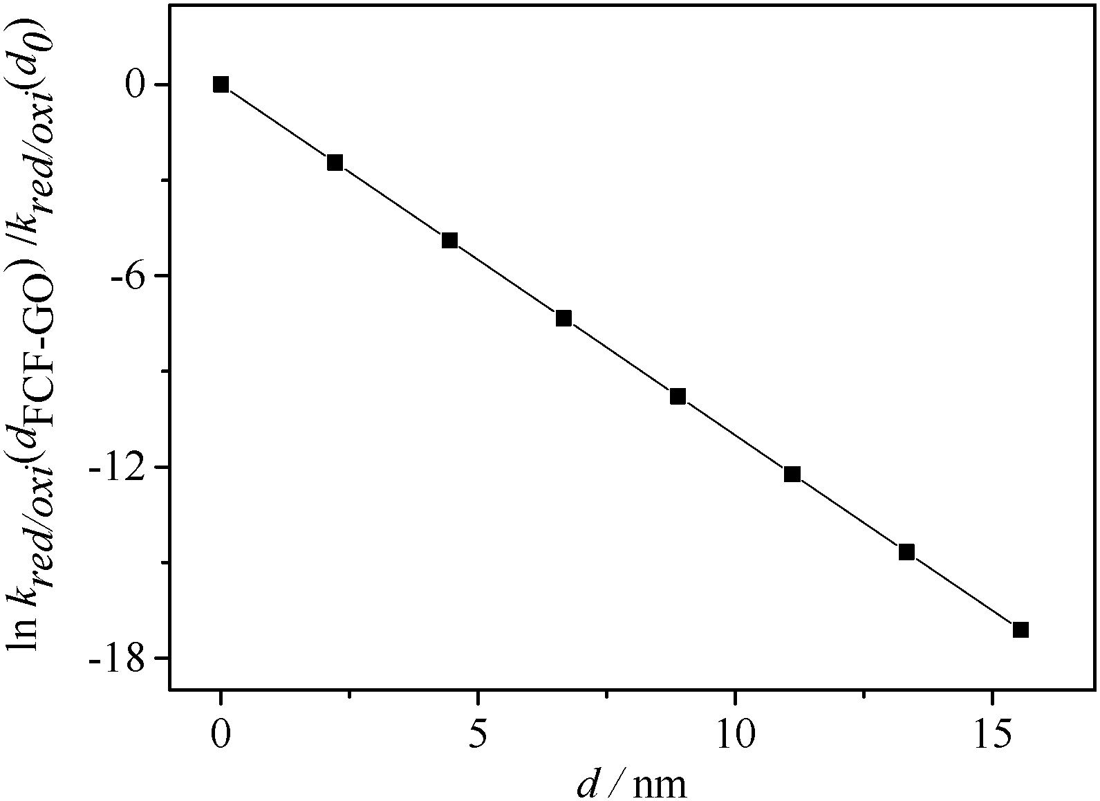
Short-range electron transfer on FCF-GO
Some studies1,7 have reported the dependence of the electron-transfer rate constant on the distance (d) between the redox center and the electrode surface. According to eqn (10), derived from the Marcus theory,16–18kred/ox decreases linearly with increasing distance (as shown in Fig. 10).
 |
| | Fig. 10 Dependence of lnkred/oxi(dFCF-GO)/kred/oxi(d0) as a function of distance (d). | |
Equation (8) can be rewritten for GOx modified by FCF-GO and FCF bioelectrodes according to eqn (11) and (12), respectively, where dFCF-GO and dFCF are the distances between the redox center and the FCF surfaces with and without graphene oxide. d0 is related to a redox center on the electrode surface (i.e., zero distance).
| | | kred/oxi(at d2) = kred/oxi(at d1)exp[−β(d2 − d1)] | (10) |
| | | kred/oxi(at dFCF-GO) = kred/oxi(at d0)exp[−β(dFCF-GO)] | (11) |
| | | kred/oxi(at dFCF) = kred/oxi(at d0)exp[−β(dFCF)] | (12) |
The electron tunneling constant (β) has been determined for a number of different redox-active self-assembled systems,56–58 and these measurements show that the tunneling constant is somewhat insensitive to the identity of a redox center for the group spacer. In this way, assuming the same β for both bioelectrodes, the ratio of dFCF-GO to dFCF is given by eqn (13):
| |  | (13) |
Substituting the electron transfer rate constants calculated from eqn (6) for FCF-GO-GOx and FCF-GOx in eqn (11), it is observed that the presence of graphene oxide decreases by half the distance between the GOx redox center and the FCF surface (dFCF-GO = 0.5 dFCF).
Thus, regarding the results yet to be obtained, further details should be considered. It is worth mentioning that in this study, the low redox current observed in voltammograms of GOx immobilized directly on FCF without treatment is attributed to the absence of GO. For redox enzymes and other biological molecules, the minimal distance between redox centers and the electrode can be expressed as the distance separating the electron donor and acceptor species. The consensus among previous reports is that in order to favor efficient electron tunneling, the distance between them should be 14 Å or less,1,7 the latter also including the photosynthetic center. In this way, the in situ-exfoliated GO decreases the distance between the FAD and the FCF, as represented in Fig. 11a. According to the JPD simulation, the FAD is not situated in the center of the enzyme. Generally (including this work) the adsorption method for enzyme immobilization does not guide the enzymes toward a specific orientation. Thus, the enzyme may adsorb randomly on the surface of the FCF. Consequently, the longest distances between the FAD and the periphery of the enzyme shell are 19.36, 19.55, and 26.38 Å. As the FEG-SEM images of the FCF without treatment showed a homogeneous morphology, one possible explanation for the low redox current of FCF-GOx bioelectrodes is the adsorption of the enzyme on the FCF through the position with minimum distance (e.g. 14.08 Å), as shown in Fig. 11b. Conversely, the presence of GO directly exfoliated from the surface of FCF facilitates the electron exchange when the enzyme is adsorbed via the positions with greater distances (e.g. 19.36, 19.55 and 26.38 Å), as can be seen simulated in Fig. 11c. The presence of GO allows the FAD exchanging electrons through positions of all simulated distances, increasing the redox current. The behavior of GO in promoting DET is well reported in the literature,60–63 as well as its special physical–chemical properties.64,65,66 In addition to these studies, which produce modified electrodes with graphene structures through two or more steps, as a result of this study we have produced a FCF electrode modified with GO to promote the DET of GOx in a single step.
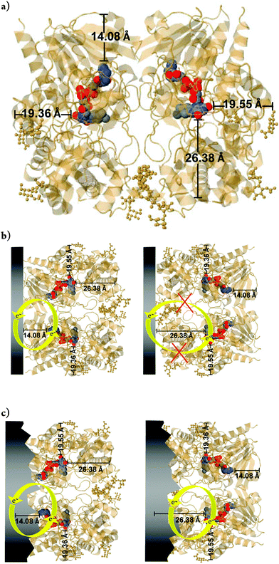 |
| | Fig. 11 (a) Position of the flavin adenine dinucleotide (FAD) within the GOx enzyme dimer. The positions were obtained from the JPD database (Jmol Version 12.2.15). The colored balls represent the FAD. (b) Example of two situations for adsorption on dimeric GOx. On the left, a dimeric-GOx molecule with SER-244 is close to the electrode surface (at the bottom). The minimum distance (d) between the flavin and the surface of the monomer is about 13 Å. On the top, glycosaminoglycan regions of dimeric-GOx are adsorbed on the electrode, with d > 13 Å. The two isoalloxazine moieties are separated by a large distance of about 40 Å. On the right, the same structure was simulated under the same conditions and directions in space, where the protein chain was omitted for better visualization of the FAD cofactor. Data simulation with point group: cyclic-C2; stoichiometry: Homo 2-mer-A2. Resolution structures can be found in ref. 59. | |
Conclusions
In this paper, we report the DET of GOx on reliably synthesized FCF electrodes modified with GO, where the khet between GO and electroactive GOx has been measured at a structurally well-defined interface. The curves obtained via the approach of Chidsey19 were used to calculate the electrochemical rate constants as a function of potential. Chidsey19 derived the relationship between ET rate constants and overpotential by integrating the Marcus equation, which describes the ET rate using the Fermi–Dirac distribution. The curve with λ = 0.38 eV was the experimentally determined value, which was used to generate the curves for FCF-GOx and FCF-GO-GOx plotted in Fig. 9. In agreement with experimental data, this model proved to be useful to systematically probe the dependence of electron transfer rates on the distance, in order to provide an empirical basis to understand the origin of interfacial DET between GO and GOx. The maximum rate constant achieved for FCF-GO-GOx was approximately twice that of FCF-GOx. Such an increase corresponds to the presence of GO structures, which facilitates the charge exchange mechanism. Substituting the electron transfer rate constants in eqn (11), it is observed that the presence of GO decreases the distance between the GOx redox center and the FCF surface by half (dFCF-GO = 0.5 dFCF). Thus, the model presented in Fig. 11 is plausible, where the presence of GO facilitates the electron exchange when the enzyme is adsorbed via the position with greater distances. We believe that the most important result in this study is the experimental and theoretical evidence that the presence of GO at the enzyme/electrode interface diminishes the activation energy by decreasing the distance between the electrode surface and the enzyme cofactor.
Acknowledgements
The authors gratefully acknowledge financial support from FAPESP (F.N. Crespilho, Project numbers: 2011/01541-0 and 2013/04663-4), CNPq (Project numbers: 304255/2010-6 and 478525/2013-3), INEO, and Rede NanoBioMed-Brasil (CAPES).
Notes and references
- Y. Degani and A. Heller, J. Am. Chem. Soc., 1988, 110, 2615–2620 CrossRef CAS.
- Y. Liu, M. Wang, F. Zhao, Z. Xu and S. Dong, Biosens. Bioelectron., 2005, 21, 984–988 CrossRef CAS PubMed.
- R. Wilson and A. P. F. Turner, Biosens. Bioelectron., 1992, 7, 165–185 CrossRef CAS.
- S. B. Bankar, M. V. Bule, R. S. Singhal and L. Ananthanarayan, Biotechnol. Adv., 2009, 27, 489–501 CrossRef CAS PubMed.
- B. A. Kuznetsov, N. M. Mestechkina and G. P. Shumakovich, Bioelectrochem. Bioenerg., 1977, 4, 1–17 CrossRef CAS.
- Y. Degani and A. Heller, J. Am. Chem. Soc., 1989, 111, 2357–2358 CrossRef CAS.
- Y. Degani and A. Heller, J. Phys. Chem., 1987, 91, 1285–1289 CrossRef CAS.
- W. Liang and Y. Zhuobin, Sensors, 2003, 3, 544–554 CrossRef.
- F. Davis and S. P. J. Higson, Biosens. Bioelectron., 2007, 22, 1224–1235 CrossRef CAS PubMed.
- J. Wang, Chem. Rev., 2008, 108, 814–825 CrossRef CAS PubMed.
- S. Zhao, K. Zhang, Y. Bai, W. Yang and C. Sun, Bioelectrochemistry, 2006, 69, 158–163 CrossRef CAS PubMed.
- A. Guiseppi-Elie, C. H. Lei and R. H. Baughman, Nanotechnology, 2002, 13, 559–564 CrossRef CAS.
- C. Shan, H. Yang, J. Song, D. Han, A. Ivaska and L. Niu, Anal. Chem., 2009, 81, 2378–2382 CrossRef CAS PubMed.
- Z. Luo, L. Yuwen, Y. Han, J. Tian, X. Zhu, L. Weng and L. Wang, Biosens. Bioelectron., 2012, 36, 179–185 CrossRef CAS PubMed.
- M. Pumera, Chem. Soc. Rev., 2010, 39, 4146–4157 RSC.
- R. A. Marcus, J. Chem. Phys., 1956, 24, 966–978 CrossRef CAS.
- R. A. Marcus, Annu. Rev. Phys. Chem., 1964, 15, 155–196 CrossRef CAS.
- R. A. Marcus and N. Sutin, Biochim. Biophys. Acta, 1985, 811, 265–322 CrossRef CAS.
- C. E. D. Chidsey, Science, 1991, 251, 919–922 CrossRef CAS PubMed.
- S. Stankovich, R. D. Piner, S. T. Nguyen and R. S. Ruoff, Carbon, 2006, 44, 3342–3347 CrossRef CAS.
- S. Stankovich, D. A. Dikin, R. D. Piner, K. A. Kohlhaas, A. Kleinhammes, Y. Jia, Y. Wu, S. T. Nguyen and R. S. Ruoff, Carbon, 2007, 45, 1558–1565 CrossRef CAS.
- N. I. Kovtyukhova, P. J. Ollivier, B. R. Martin, T. E. Mallouk, S. A. Chizhik, E. V. Buzaneva and A. D. Gorchinskiy, Chem. Mater., 1999, 11, 771–778 CrossRef CAS.
- A. Sassolas, L. J. Blum and B. D. Leca-Bouvier, Biotechnol. Adv., 2012, 30, 489–511 CrossRef CAS PubMed.
- R. M. Iost and F. N. Crespilho, Biosens. Bioelectron., 2012, 31, 1–10 CrossRef CAS PubMed.
- E. Laviron, J. Electroanal. Chem., 1979, 100, 263–270 CrossRef CAS.
- M. D. Stoller, S. Park, Y. Zhu, J. An and R. S. Ruoff, Nano Lett., 2008, 8, 3498–3502 CrossRef CAS PubMed.
- C. Fu, W. Yang, X. Chen and D. G. Evans, Electrochem. Commun., 2009, 11, 997–1000 CrossRef CAS.
- F. C. Tai, C. Wei, S. H. Chang and W. S. J. Chen, Raman Spectrosc., 2010, 41, 933–937 CrossRef CAS.
- Z. Ni, Y. Wang, T. Yu and Z. Shen, Nano Res., 2008, 1, 273–291 CrossRef CAS.
- A. C. Ferrari, Solid State Commun., 2007, 143, 47–57 CrossRef CAS.
- G. K. Ramesha and S. Sampath, J. Phys. Chem. C, 2009, 113, 7985–7989 CAS.
- W. Gao, L. B. Alemany, L. Ci and P. M. Ajayan, Nat. Chem., 2009, 1, 403–408 CrossRef CAS PubMed.
- C. C. Page, C. C. Moser, X. Chen and P. L. Dutton, Nature, 1999, 402, 47–52 CrossRef CAS PubMed.
- C. Hontorialucas, A. J. Lopezpeinado, J. D. D. Lopezgonzalez, M. L. Rojascervantes and R. M. Martinaranda, Carbon, 1995, 33, 1585–1592 CrossRef CAS.
- T. Szabo, O. Berkesi and I. Dekany, Carbon, 2005, 43, 3186–3189 CrossRef CAS.
- G. I. Titelman, V. Gelman, S. Bron, R. L. Khalfin, Y. Cohen and H. Bianco-Peled, Carbon, 2005, 43, 641–649 CrossRef CAS.
- A. Salimi, E. Sharifi, A. Noorbakhsh and S. Soltanian, Biosens. Bioelectron., 2007, 22, 3146–3153 CrossRef CAS PubMed.
- Y. Xiao, F. Patolsky, E. Katz, J. F. Hainfeld and I. Willner, Science, 2003, 299, 1877–1881 CrossRef CAS PubMed.
- Y. Zhang, Y. Shen, D. Han, Z. Wang, J. Song, F. Li and L. Niu, Biosens. Bioelectron., 2007, 23, 438–443 CrossRef PubMed.
- S. Yang, X. Feng, L. Wang, K. Tang, J. Maier and K. Müllen, Angew. Chem., Int. Ed., 2010, 49, 4795–4799 CrossRef CAS PubMed.
- D. R. Dreyer, S. Park, C. W. Bielawski and R. S. Ruoff, Chem. Soc. Rev., 2010, 39, 228–240 RSC.
-
A. J. Bard and L. R. Faulkner, Electrochemical Methods: Fundamentals and Applications, John Wiley & Sons, New York, 2nd edn, 2001 Search PubMed.
- B. E. P. Swoboda and V. Massey, J. Biol. Chem., 1965, 240, 2209–2215 CAS.
- R. Lumry and H. Eyring, J. Phys. Chem., 1954, 58, 110–120 CrossRef CAS.
- J. M. Sanchez-Ruiz, Biophys. J., 1954, 61, 921–935 CrossRef.
- W. J. Luo, C. F. Zhu, S. Su, D. Li, Y. He, Q. Huang and C. H. Fan, ACS Nano, 2010, 4, 7451–7458 CrossRef CAS PubMed.
- G. Zoldák, A. Zubrik, A. Musatov, M. Stupák and E. Sedlák, J. Biol. Chem., 2004, 279, 47601–47609 CrossRef PubMed.
-
F. Scholz, Electroanalytical Methods: Guide to Experiments and Applications, Springer, New York, 2nd edn, 2010 Search PubMed.
- J.-M. You and S. Jeon, Electroanalysis, 2011, 23, 2103–2108 CrossRef CAS.
- B. Q. Wang, B. Li, Q. Deng and S. Dong, J. Anal. Chem., 1998, 70, 3170–3174 CAS.
- W.-Z. Jia, K. Wang, Z.-J. Zhu, H.-T. Song and X.-H. Xia, Langmuir, 2007, 23, 11896–11900 CrossRef CAS PubMed.
- H. A. Heering, J. Hirst and F. A. Armstrong, J. Phys. Chem. B, 1998, 102, 6889–6902 CrossRef CAS.
- L. Tender, M. T. Carter and R. W. Murray, Anal. Chem., 1994, 66, 3173–3181 CrossRef CAS.
- A. L. Eckermann, D. J. Feld, J. A. Shaw and T. J. Meade, Coord. Chem. Rev., 2010, 254, 1769–1802 CrossRef CAS PubMed.
- K. Weber and S. E. Creager, Anal. Chem., 1994, 66, 3164–3172 CrossRef CAS.
- C. Miller, P. Cuendet and M. Gratzel, J. Phys. Chem., 1991, 95, 877–886 CrossRef CAS.
- O. H. Finklea and D. D Hanshew, J. Am. Chem. Soc., 1992, 114, 3173–3181 CrossRef.
- H.-G. Hong and W. Park, Langmuir, 2001, 17, 2485–2492 CrossRef CAS.
- G. S. Wohlfahrt, J. Witt, D. Hendle, H. Schomburg, M. Kalisz and H. Hecht, J. Acta Crystallogr., 1999, 55, 969–977 CAS.
- C. Shan, H. Yang, J. Song, D. Han, A. Ivaska and L. Niu, Anal. Chem., 2009, 81, 2378–2382 CrossRef CAS PubMed.
- X. Kang, J. Wang, H. Wu, I. A. Aksay, J. Liu and Y. Lin, Biosens. Bioelectron., 2009, 25, 901–905 CrossRef CAS PubMed.
- Y. Shao, J. Wang, H. Wu, J. Liu, I. A. Aksay and Y. Lin, Electroanalysis, 2010, 22, 1027–1036 CrossRef CAS.
- P. Wu, Q. Shao, Y. Hu, J. Jin, Y. Yin, H. Zhang and C. Cai, Electrochim. Acta, 2010, 55, 8606–8614 CrossRef CAS.
- X. Li, G. Zhang, X. Bai, X. Sun, X. Wang, E. Wang and H. Dai, Nat. Nanotechnol., 2008, 3, 538–542 CrossRef CAS PubMed.
- Y. B. Zhang, Y. W. Tan, H. L. Stormer and P. Kim, Nature, 2005, 438, 201–204 CrossRef CAS PubMed.
- D. Li, M. B. Mueller, S. Gilje, R. B. Kaner and G. G. Wallace, Nat. Nanotechnol., 2008, 3, 101–105 CrossRef CAS PubMed.
Footnote |
| † Electronic supplementary information (ESI) available: Details of the synthesis of GO, immobilization of GOx, XRD of FCF and FCF-GO and cyclic voltammetry. See DOI: 10.1039/c4cp00452c |
|
| This journal is © the Owner Societies 2014 |
Click here to see how this site uses Cookies. View our privacy policy here.