 Open Access Article
Creative Commons Attribution 3.0 Unported Licence
A promising Na3V2(PO4)3 cathode for use in the construction of high energy batteries
Weixin
Song
a,
Xiaobo
Ji
*a,
Yinpeng
Yao
a,
Hanjun
Zhu
a,
Qiyuan
Chen
a,
Qinqin
Sun
a and
Craig E.
Banks
*b
aKey Laboratory of Resources Chemistry of Nonferrous Metals, Ministry of Education, College of Chemistry and Chemical Engineering, Central South University, Changsha, 410083, China. E-mail: xji@csu.edu.cn; Fax: +86 731 88879616
bFaculty of Science and Engineering, School of Science and the Environment, Division of Chemistry and Environmental Science, Manchester Metropolitan University, Chester Street, Manchester M1 5GD, Lancs, UK. E-mail: c.banks@mmu.ac.uk; Fax: +44(0) 1612476831
First published on 7th January 2014
Abstract
High-energy batteries need significant cathodes which can simultaneously provide large specific capacities and high discharge plateaus. NASICON-structured Na3V2(PO4)3 (NVP) has been utilised as a promising cathode to meet this requirement and be used in the construction of high energy batteries. For a hybrid-ion battery by employing metallic lithium as an anode, NVP exhibits an initial specific capacity of 170 mA h g−1 in the voltage range of 1.6–4.8 V with a long discharge plateau around 3.7 V. Three Na(2) sites for NVP are found capable to be utilised through the application of a wide voltage window but only two of them are able to undergo ions exchange to produce a NaLi2V2(PO4)3 phase. However, a hybrid-ion migration mechanism is suggested to exist to describe the whole ion transport in which the effects of a Na-ion “barrier” results in a lowered ion diffusion rate and observed specific capacity.
1. Introduction
Lithium-ion battery (LIB) technology is critically needed for many applications in a plethora of industries and is an important energy-storage solution which can be potentially applied, for instance into electric vehicles (EVs).1,2 However, LIB has continued to be primarily relegated by the electronics market mainly due to its cost and material issues3 and the lack of high-performance cathode materials have become a technological bottleneck for the commercial development of advanced LIB.4 Particularly for the entrance of LIB into high energy fields, such as EVs and renewable energy storage in smart grids, the demand for high-capacity and voltage cathodes is starting to become a key focus of research.In the search for new positive-electrode materials for LIB, recent research has focused upon nano-structured lithium transitional-metal phosphates that exhibit desirable properties such as high energy storage capacities combined with electrochemical stability.5,6 Olivine LiFePO4,7 as one member of this class, has risen to prominence so far due to other characteristics involving low cost, low environmental impact and safety, which are critical for large-capacity systems to be implemented. Nonetheless, olivine also has some shortcomings including the one-dimensional lithium-ion transport and two-phase redox reaction that together limit the mobility of the phase boundary as well as the emerging safe hazard.6 Meanwhile, the availability of readily-accessible lithium is a key concern and as supplies reduce, costs will rise which will be passed on to the end consumers such that Li-ion batteries will become too costly.8
Recently, tremendous attention has been focused on sodium-ion batteries (SIB) with NASICON (a Na superior conductor)-structured compounds been brought to the forefront of scientific investigation. These NASICON-type compounds are lithium ion free, and as such overcome the inherent disadvantages as described above. The NASICON-type compounds based materials feature a highly covalent three-dimensional framework that generates large interstitial spaces through which sodium ions may diffuse,9,10 with compounds such as Na3M2(PO4)3 (M = Ti, Fe, V)3,11–13 and Na3V2(PO4)2F314,15 reported. In particular, Na3V2(PO4)3 (NVP) has been demonstrated recently as a prospective cathode material for use as sodium ion3,12,16 or hybrid-ion batteries (HIB),17 while the composition of phosphate-based Na-insertion hosts is advantageous due to the strong covalent (PO4)3− units that provide structural stability even at high charge states and address thermal safety concerns unlike commercial Li-insertion oxide hosts.13,18,19 Furthermore, its intrinsically well-defined NASICON channel structure facilitates excellent ionic conductivity1 and results in useful performances in terms of specific capacity, rate capability and cycle life. Furthermore, various analyses at different temperatures have shown that NVP holds good thermal stability, thus suggesting the safe nature of this material which is also critical for large-scale utility grid applications.20
NVP displays two potential plateaus at 3.4 V and 1.6 V vs. Na+/Na, related to the V3+/V4+ and V2+/V3+ redox couples, and these two reaction voltages correspond to a specific capacity of 117 and 50 mA h g−1 for the high and low voltage zones, respectively. Lim et al. has correlated these two plateaus with the energies calculated for different Na distributions in the phase, from which a two-phase reaction is expected to form two energetically favorable phases.20 There are two crystallographic sites to accommodate Na ions in NVP compound, of which the Na(1) site is proved to remain totally occupied with one Na ion while the Na(2) site is active when the sodium content changes from Na3V2(PO4)3 to NaV2(PO4)3 in a specialised voltage range. However, the extraction of all three Na ions with a theoretical capacity of 176 mA h g−1 is kinetically difficult due to the much lower electronic/ionic conductivity of the end-member of V2(PO4)3,17,21 therefore two-thirds of the ions are capable to be reversibly extracted/inserted and give rise to a theoretical capacity of 117 mA h g−1. For this NASICON structure, a Na4V2(PO4)3 phase could be formed if all three Na(2) sites are occupied by Na ions with a resulting theoretical capacity of 234 mA h g−1 provided four Na per formula could extracted.
To the best of our knowledge, only one paper has reported the highest value of 234 mA h g−1 utilizing NVP cathodes.13 Na3V2(PO4)3 can be considered as a promising cathode material exhibiting a high capacity and voltage range (3.7 V and 1.9 V vs. Li+/Li). Herein, a solution-based carbothermal reduction method (S-CTR) is adopted as an improved synthetic methodology compared with carbothermal reduction (CTR) approaches to fabricate NVP materials. Based on the configuration of a NVP/LiPF6/Li hybrid-ion battery, a high capacity of 170 mA h g−1 is produced with good C-rate and cycling performances.
2. Experimental
A developed CTR synthetic methodology, named S-CTR was employed for the preparation of the NVP which involves the following steps. 1.41 g Na2CO3, 2.5 g NH4H2PO4 and 1.32V2O5 were used in stoichiometric proportions to form a mixed solution by stirring in 50 mL distilled water. This mixture was then dried at 50 °C via forced-air drying with the obtained solid ground by adding 0.34 g of an acetylene black powder. All the reagents used were of the highest analytical purity available and were used without any further purification. The precursor was preheated at 350 °C in flow argon for 4 h, reground and re-fired at 650, 700 and 750 °C in argon atmosphere for 8 h, respectively. NVP was prepared by a CTR methodology as in accordance with the literature21 to provide a critical comparison.In order to obtain the crystal structure of the compound, X-ray powder diffraction (XRD) analyses were performed by using a Bruker D8 diffractometer with monochromatic Cu Kα radiation (λ = 1.5406 Å), and the diffraction data was recorded in the 2θ range of 10–60° with a scan rate of 8° per min. The infrared (IR) spectra was obtained using an FT-IR Spectrometer (Jasco, FT/IR-4100, Japan) under transmission mode based on the KBr pellet method in the range of 500–2000 cm−1. The particle morphology of the composite was investigated by a FEI Quanta 200 scanning electron microscopy (SEM). The thermogravimetric analysis (TG) of the samples was carried on a Diamond TG thermo-analyzer.
The cathode electrode was composed of active NVP material, acetylene black, and binder (Polyvinylidene Fluoride, PVDF) in a weight ratio of 8![[thin space (1/6-em)]](https://www.rsc.org/images/entities/char_2009.gif) :
:![[thin space (1/6-em)]](https://www.rsc.org/images/entities/char_2009.gif) 1
1![[thin space (1/6-em)]](https://www.rsc.org/images/entities/char_2009.gif) :
:![[thin space (1/6-em)]](https://www.rsc.org/images/entities/char_2009.gif) 1 by using NMP as solvent and an aluminum foil as current collector (∼4.5 mg cm−2), followed by drying in vacuum at 110 °C for 24 h. To evaluate the electrochemical properties, a R2016 coin cell was assembled in an argon-filled glove box using metallic lithium as anode, Celgard 2500 membrane as separator. The electrolyte was 1 M LiPF6 dissolved in a mixture of ethylene carbonate (EC), dimethyl carbonate (DMC), diethyl carbonate (DEC) (v/v/v, 1/1/1).
1 by using NMP as solvent and an aluminum foil as current collector (∼4.5 mg cm−2), followed by drying in vacuum at 110 °C for 24 h. To evaluate the electrochemical properties, a R2016 coin cell was assembled in an argon-filled glove box using metallic lithium as anode, Celgard 2500 membrane as separator. The electrolyte was 1 M LiPF6 dissolved in a mixture of ethylene carbonate (EC), dimethyl carbonate (DMC), diethyl carbonate (DEC) (v/v/v, 1/1/1).
Cyclic voltammetry (CV) and galvanostatic charge–discharge cycling tests were carried out in a setting voltage range by using an electrochemical workstation (CHI660C) and CT2001A LAND battery tester, respectively. Electrochemical impedance spectroscopy (EIS) was studied using a Modulab (Solartron Analytical) with the amplitude of 5 mV in the frequency range from 1 MHz to 10 mHz. All electrochemical tests were carried out at room temperature.
3. Results and discussion
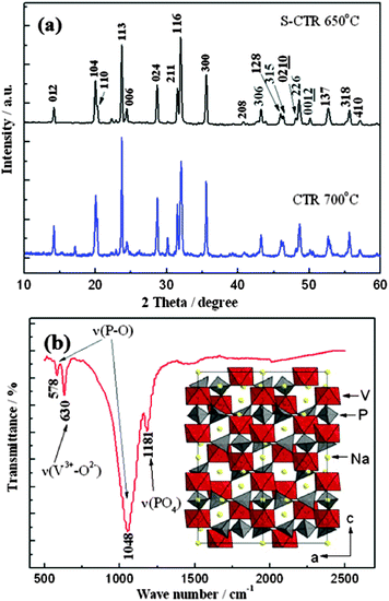
The power XRD patterns of NVP prepared by S-CTR and CTR at 650 and 700 °C are shown in Fig. 1a, respectively. For comparison, all of the diffraction peaks are indexed to the R![[3 with combining macron]](https://www.rsc.org/images/entities/char_0033_0304.gif) c space group (Rhombohedral unit with 2 Na in 18e position and 1 Na in 6b position) and are in good agreement with the results of the NASICON framework.3,9,12 Clearly, no redundant peaks at 17 and 30.2° have appeared for the sample prepared by S-CTR when compared with the XRD patterns from CTR sample. This could indicate the formation of a pure NVP mainly on account of the solution-based admixture by improving particle contact when stirred, as undertaken as part of the synthetic methodology (see Experimental). Fig. 1b shows the FT-IR analysis of S-CTR NVP which is in good agreement with Jang's work,20 from which the bands indicate good crystallization due to the observation of peaks present; the bands at 578 and 1048 cm−1 suggest the presence of P–O bonds of PO4 tetrahedra and the vibration from V3+–O2− bonds in isolated VO6 octahedra are evident at 630 cm−1. Moreover, the infrared bands in the range of 1150–1250 cm−1 can be attributed to the stretching vibration of terminal PO4 units,22 while the bands at 760 and 950 cm−1 which are characteristic of the occurrence of V5+ in VO6 octahedra were not observed indicating that the V5+ in V2O5 have been reduced to V3+ in NVP. Thus, the combined results of XRD and FT-IR demonstrate the rhombohedral NASICON characteristic of S-CTR NVP. The corresponding crystal structure was simulated and presented in the inset of Fig. 1b. The structural image shows that the octahedral VO6 interlinks via corners with tetrahedral PO4 to establish the polyanion [V2(PO4)3] units in the c-axis direction which were interconnected through PO4 to the same neighboring units, and each primitive cell of NVP contains six formula units built up from [V2(PO4)3] framework anion and two different oxygen environment sodium atoms, of which the first one is six fold coordination [Na(1)] and the other is eight fold coordination [Na(2)].
c space group (Rhombohedral unit with 2 Na in 18e position and 1 Na in 6b position) and are in good agreement with the results of the NASICON framework.3,9,12 Clearly, no redundant peaks at 17 and 30.2° have appeared for the sample prepared by S-CTR when compared with the XRD patterns from CTR sample. This could indicate the formation of a pure NVP mainly on account of the solution-based admixture by improving particle contact when stirred, as undertaken as part of the synthetic methodology (see Experimental). Fig. 1b shows the FT-IR analysis of S-CTR NVP which is in good agreement with Jang's work,20 from which the bands indicate good crystallization due to the observation of peaks present; the bands at 578 and 1048 cm−1 suggest the presence of P–O bonds of PO4 tetrahedra and the vibration from V3+–O2− bonds in isolated VO6 octahedra are evident at 630 cm−1. Moreover, the infrared bands in the range of 1150–1250 cm−1 can be attributed to the stretching vibration of terminal PO4 units,22 while the bands at 760 and 950 cm−1 which are characteristic of the occurrence of V5+ in VO6 octahedra were not observed indicating that the V5+ in V2O5 have been reduced to V3+ in NVP. Thus, the combined results of XRD and FT-IR demonstrate the rhombohedral NASICON characteristic of S-CTR NVP. The corresponding crystal structure was simulated and presented in the inset of Fig. 1b. The structural image shows that the octahedral VO6 interlinks via corners with tetrahedral PO4 to establish the polyanion [V2(PO4)3] units in the c-axis direction which were interconnected through PO4 to the same neighboring units, and each primitive cell of NVP contains six formula units built up from [V2(PO4)3] framework anion and two different oxygen environment sodium atoms, of which the first one is six fold coordination [Na(1)] and the other is eight fold coordination [Na(2)].
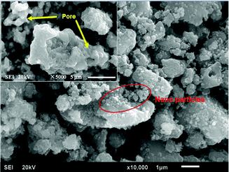
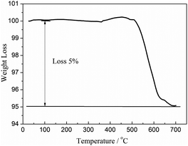
The morphology and surface structure of the S-CTR NVP was characterized by SEM with the images depicted in Fig. 2. It is clearly that nano-particles are adhered to the surface of the bulk material where the irregularly shaped particles are distributed over the size range of 1–5 μm, likely as a result from the molecular mixing and mechanically chemical activation processes applied before sintering. Additionally, the malformed surface structures, as shown in the inset of Fig. 2, along with the secondary particles formed by particle agglomeration have resulted in NVP exhibiting many pores which can be useful for the facilitation of electrolyte ions transport.15 Furthermore, the growth of NVP particles is considered to be hindered by the amount of available source of carbon from CTR methodology as evidence by measuring the residual carbon with a content of 5% in the NVP–C composite calculated to be ∼5% from TG curves as shown in Fig. 3 and will contribute to improve the electron transport between particles, which further enhance the power density. Graphene has been used as conducting support for olivine-based LiFePO4 batteries with negligible fading even after several hundreds of cycles,23 and would also be appropriate for use in NVP battery due to its favorably structural impacts on electrochemical performances.24 Additionally graphene-based nanomaterials for energy storage have been reviewed25 displaying the progresses of battery properties by utilizing graphene.
Hybrid-ion batteries have been described by Barker et al.26 who investigated the mixed Na/Li insertion/extraction mechanism, and an analogical work based on the NVP/Li hybrid-ion battery has been explored recently.21Fig. 4 shows the anterior eight CV cycles at a scan rate of 0.5 mV s−1 in a voltage range from 2 to 4.8 V vs. Li+/Li. The anodic reaction could be attributed to Na extraction in the first cycle with an anodic peak present while the sequential cathodic processes with only one voltammetric peak indicates a Na/Li hybrid-ion insertion as a result of the irreversibility of Na ion and the vast excess of Li in this hybrid-ion system. One couple of redox peaks would be presented provided that the inserted ions are all Na as depicted in a sodium-ion battery.27 As described previously,17,21 the redox couple in this voltage range is assigned to the V3+/V4+ reaction which is accompanied by migration of two mixed alkali ions. Interestingly, the voltammetric cycles have presented only one redox couple indicating that mixed ion behavior has become predominantly Li-ion transport in the cycling, with the exhibited excellent symmetry of the 4th and 8th CV curves also demonstrating good reversibility of the material.17 Combined with our previous analysis, the utilized NVP electrode could produce an easy and adequate ion-exchange with Li-based electrolytes undergoing potential cycling or standing process for the formation of Li2NaV2(PO4)321 while the exchanged Na ion prefers to be at Na(2) sites.10
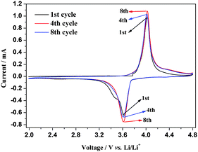 | ||
| Fig. 4 Anterior eight CV cycles of S-CTR NVP at 0.5 mV s−1 in a voltage range of 2–4.8 V vs. Li+/Li. | ||
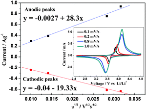
The hybrid-ion battery after proceeding 10 CV cycles at 0.5 mV s−1 in a voltage range of 2.5–4.8 V vs. Li+/Li, continued to be tested at 0.1, 0.2, 0.8 and 1 mV s−1, respectively, and the results are displayed in the inset of Fig. 5. The phase of Li2NaV2(PO4)3 could be responsible for the only one obvious redox couple during CV tests without any visible effects from the insertion/desertion behaviors of Na+ ions. The good linear relationships between the square root of the scan rate v1/2 and peak current ip depicted in Fig. 5 illustrates a diffusion-controlled process for the electrochemical reaction and a typical equilibrium behavior of an intercalated type electrode. Thus, it is worthwhile to explore the chemical diffusion coefficient for further understanding of NVP electrode. Randles–Sevcik equation (eqn (1)) could be employed to determine the diffusion constant D which describes the relationship between the peak current ip and the square root of the scan rate v1/2:
| ip/m = 0.4463(F3/RT)1/2n3/2AD1/2Cv1/2 | (1) |
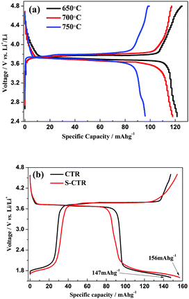
As shown in Fig. 6a the hybrid-ion batteries using S-CTR NVP prepared at 650, 700 and 750 °C display an initial discharge capacity of 122, 117 and 96 mA h g−1, respectively, at 0.1 C (Note that 0.1 C refers to two Na extraction from the NVP per formula unit in 10 h) in a voltage range of 2.5–4.8 V vs. Li/Li+, demonstrating a better performance of NVP prepared at optimized 650 °C. Under the same hybrid-ion system, NVP prepared by S-CTR at 650 °C could exhibit a higher initial discharge capacity of 156 mA h g−1 than that prepared by CTR at 700 °C with a capacity of 147 mA h g−1 at 0.1 C between 1.6 and 4.6 V vs. Li/Li+ as shown in Fig. 6b, mainly resulting from the improved synthesized method for NVP. Additionally in order to obtain a large specific capacity of NVP in a hybrid-ion battery, various voltage windows, which could decide the inserted/extracted ion number for NVP, were applied to explore the exhibited electrochemical performances as shown in Fig. 7 and Fig. 8. The hybrid-ion batteries using S-CTR NVP cathodes displayed the initial discharge capacities of 158, 157, 96 mA h g−1 from 1.5, 1.6, 2.3 to 4.6 V vs. Li/Li+ (Fig. 7a), and 170, 170, 110 mA h g−1 from 1.5, 1.6, 2.3 to 4.8 V vs. Li/Li+ (Fig. 7b), respectively. The cycling performances at various C-rates of NVP in a voltage range of 1.6–4.6 V vs. Li/Li+ for S-CTR NVP could be thought to be satisfying compared with those for CTR NVP. The average discharge capacities are 156, 138, 116, 95 and 80 mA h g−1 for S-CTR NVP and 126, 110, 75, 64 and 56 mA h g−1 for CTR NVP at 0.1, 0.2, 0.5, 1 and 2 C, respectively, as shown in Fig. 8a. Meanwhile, a discharge capacity of 124 mA h g−1 for the 140th galvanostatic cycles was also displayed. Interestingly, Fig. 8b has depicted acceptable cycling performances for this hybrid-ion battery with a discharge capacity of 140 mA h g−1 after 50 cycles at 0.1 C when the utilized voltage rises to 4.8 V vs. Li/Li+.
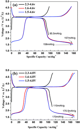 | ||
| Fig. 7 Initial charge–discharge profiles of S-CTR NVP prepared at 650 °C at 0.1 C within a voltage range of (a) 1.5, 1.6, 2.3–4.6 V vs. Li/Li+, (b) 1.5, 1.6, 2.3–4.8 V vs. Li/Li+. | ||
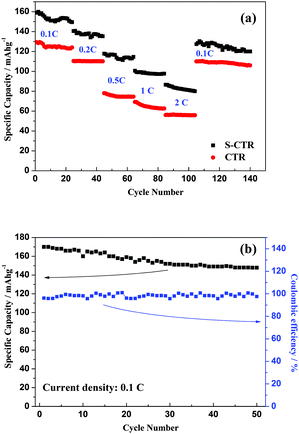 | ||
| Fig. 8 (a) Cycling performances at various C-rates for S-CTR and CTR NVP in a voltage range of 1.6–4.6 V vs. Li/Li+, and (b) at 0.1 C for S-CTR NVP between 1.6 and 4.8 V vs. Li/Li+. | ||
As far as we know, there are still few reports corresponding to the electrochemical data toward to NVP, and these compared values reported in related literatures have been listed in Table 1.
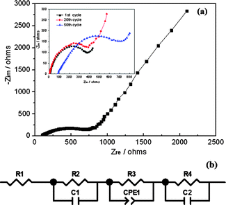
Next, EIS was further used to investigate the electrochemical kinetics of NVP electrode when it is cycled after 1, 20 and 50 cycles and charged to a same voltage of 3.7 V. The Nyquist plots and corresponding fitted equivalent circuit model are presented in Fig. 9(a and b). All the impedance parameters with relative errors estimate (%) of the fitting equivalent circuit are listed in Table 2 by using ZSimWin software with each chi-squared function (χ2) less than 10−4, by which the value of chi-squared function between 10−5 and 10−4 could provide a reasonably good indication of the quality of the fit.28R1 represents the internal resistance involving the resistance of the electrolyte and electrode which is denoted as the small intercept at the Zre axis. R2 corresponds to the resistance of SEI film as depicted in the high frequency region of the semi-circle, while C1 signifies the resultant capacitance from SEI film. R3 is the charge transfer resistance in the intermediate-frequency region and CPE1 is related to the surface property of the electrode. R4 denotes the Warburg resistance originated from the diffusion of Na+ ions in the electrode bulk as depicted in the low frequency region of the sloping line. C2 demonstrate the double layer capacitance caused by ion transfer in the electrode material. As can be observed from inspection of Fig. 9a, the internal resistance and charge transfer resistance of the 50th cycle are obviously increasing compared with that of the 1st and 20th cycle, which could be attributed to the cycling influence. In addition, the nearly 45° sloping line of Nyquist plots at low frequency corresponding to the solid-state diffusion of ions in the active materials, further confirmed the electrochemistry process of NVP as a diffusion-controlled rather than surface-controlled reaction.
| R 1 (Ω cm−2) | R 2 (Ω cm−2) | C 1 (F cm−2) | R 3 (Ω cm−2) | CPE1 (Ss1/2 cm−2) | R 4 (Ω cm−2) | C 2 (F cm−2) | |
|---|---|---|---|---|---|---|---|
| Results | 85.34 | 367.6 | 7.6 × 10⁻⁴ | 826.7 | 3.86 × 10⁻⁵ | 93.1 | 6.3 × 10⁻⁴ |
| Error (%) | 1.534 | 7.291 | 6.068 | 1.17 | 4.548 | 5.78 | 1.769 |
As shown in Scheme 1, two kinds of crystalline Na sites namely Na(1) and Na(2) sites are displayed, of which one Na(1) site retains to be occupied by Na ion while two Na(2) sites are occupied by Li ions resulting from the ion-exchange occurring in cycling or standing exchange. This description could be thought appropriately due to the ion-transport mechanism suggested by Goodenough et al.10 and our previous works.21 According to this conclusion, NaLi2V2(PO4)3 could be reasonably formed from NVP by ion exchange with Li ions, while the left Na ion could be considered stationary at Na(1) site. The exchanged Li ions are able to occupy the two Na(2) sites which held Na ions before, or re-exchange only between these two sites. The ion-exchange mechanism for NaLi2V2(PO4)3 is firstly demonstrated in eqn (2) and (3), where the number in parentheses denotes the alkali ions in Na(1) or Na(2) sites, the value in the bottom right corner signifies series number of the ions and γ represents a vacancy in Na(2) sites.
| Na1+(2) + Na2+(2) + γ(2) + Na+(1) + 2Li+ → Na+(1) + γ(2) + Li1+(2) + Li2+(2) + 2Na+ | (2) |
| Li1+(2) + Li2+(2) + γ(2) + Na+(1) + Li+ → Na+(1) + γ(2) + Li1+(2) + Li2+(2) + Li+ | (3) |
| Li1+(2) + Li2+(2) + Li3+(2) + Na+(1) + Li+ → Na+(1) + Li1+(2) + Li2+(2) + Li3+(2) + Li+ | (4) |
However, the vacancy at Na(2) site has been thought capable to be shoehorned with one alkali ion by electrochemical means, such as an enlarged voltage window.21Fig. 10 exhibits the electrochemical voltage-composition curves of the first galvanostatic cycle at a current rate of 0.1 C for NVP hybrid-ion battery in a voltage range of 1.6–4.8 V vs. Li/Li+, of which the inserted alkali ions are presumably as Li ions. The different number of ions (Δx) in charge (1.7) and discharge (1.4) around the plateau of near 3.7 V demonstrates a hybrid-ion extraction/insertion behavior composed by un-ion-exchanged Na+ ions and ion-exchanged Li+ ions, because the irreversibility mainly from SEI resistance for Na+ ions would cost larger energy (charging capacity) to make ion migrate, but smaller and lighter Li+ ions have substituted Na+ ions to insert into the NASICON structure which only need less energy (discharging capacity). Up until the discharging voltage of 1.6 V, the number of lithium ions (x) in NaLixV2(PO4)3 is about 2.9 and two-phase transitions assigned to V3+/V4+ and V2+/V3+ redox reactions should be responsible for this result. The first transition is divided into two ion-insertion steps corresponding two discharge plateaus, of which the insertion of two ions is completed until 1.9 V vs. Li/Li+ and the second transition realizing a mixed V(II/III) would rationally be ascribed to the inserted 0.9 ion until the cut-off voltage of 1.6 V vs. Li/Li+. By employing Faraday's Law (C = 26.8n/M A h g−1, where C is the theoretical capacity of the active material, n is the number of electrons in reaction and M is the relative molecular mass) to calculate the discharge capacity when 2.9 Li ions are transported, a theoretical value of 181 mA h g−1 could be obtained which is larger than the experimental figures. One reason, which has been pointed out is that the back ions are mixed with less heavier Na+ ions while here, the impeding influences from Na ions towards Li ions “barrier” in a synchronous insertion which could be indicated specifically to indicate the lower D as analyzed above. Another probable factor might be the restraint of Na ions to lower the inserted number of Li ions attributed to the barrier between them. Actually, the discharge capacity of 170 mA h g−1 corresponds to an insertion with only 2.7 Li ions, where this overcoming towards to the produced barrier should contribute to the redundant inserted 0.2 ions. It is known that in order to overcome this, significant energy is required which could be attributed to the effects of the insertion of 0.2 ions according to Faraday's Law. Moreover, the inserted ions (excess two) should take up three Na(2) sites while the vacancy seems prior to be occupied with Li ion due to the smaller and lighter characters to produce Li3+(2). The ion of Li3+(2) is suggested to be difficult to exchange with other ions because this behavior would require significant energy as described by eqn (4), otherwise the vacancy would be occupied with lithium ions to present unstable NaLi3V2(PO4)3 which is not consistent with ICP results.17,21 However, this vacancy has been utilized by ion insertion and a promising cathode material is realized exhibiting 170 mA h g−1 at a discharge voltage plateau around 3.7 V; as such this material would be suitable for the construction of a high-energy battery.
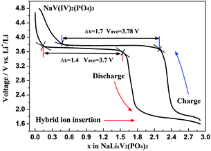 | ||
| Fig. 10 Electrochemical voltage-composition curves of the first galvanostatic cycle at a current rate of 0.1 C for NVP hybrid-ion battery. | ||
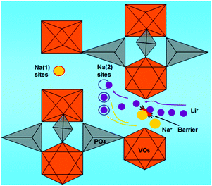 | ||
| Scheme 1 Representation of NASICON-structure NVP exhibiting the ion-exchange for Na with Li ions and the Li-insertion process. | ||
4. Conclusion
A NVP cathode was synthesized with an improved CTR method and used in a hybrid-ion battery to explore its electrochemical properties. The satisfying performances of 170 mA h g−1 with a discharge voltage plateau around 3.7 V were presented as a result of the predominantly Li ion transport in cycling. Reasonably, a NaLi2V2(PO4)3 phase should be responsible for this properties while the utilization of the three Na(2) sites for NVP could be associated with the applied voltage windows. Based on the ion-transport mechanism as suggested, two Na(2) sites can allow the ions to exchange while the last one site with vacancy before could be used to accommodate alkali ions. Meanwhile, a hybrid-ion migration is supported to exist in the whole ion transport, and the adverse effects from Na ion on the ion diffusion rate and the specific capacity of the hybrid-ion system have been investigated.Notes and references
- M. Armand and J. M. Tarascon, Nature, 2008, 451, 652–657 CrossRef CAS PubMed.
- B. Dunn, H. Kamath and J.-M. Tarascon, Science, 2011, 334, 928–935 CrossRef CAS PubMed.
- K. Saravanan, C. W. Mason, A. Rudola, K. H. Wong and P. Balaya, Adv. Energy Mater., 2013, 3, 444–450 CrossRef CAS.
- N.-S. Choi, Z. Chen, S. A. Freunberger, X. Ji, Y.-K. Sun, K. Amine, G. Yushin, L. F. Nazar, J. Cho and P. G. Bruce, Angew. Chem., Int. Ed., 2012, 51, 9994–10024 CrossRef CAS PubMed.
- A. S. Arico, P. Bruce, B. Scrosati, J.-M. Tarascon and W. van Schalkwijk, Nat. Mater., 2005, 4, 366–377 CrossRef CAS PubMed.
- B. L. Ellis, W. R. M. Makahnouk, Y. Makimura, K. Toghill and L. F. Nazar, Nat. Mater., 2007, 6, 749–753 CrossRef CAS PubMed.
- A. K. Padhi, K. S. Nanjundaswamy and J. B. Goodenough, J. Electrochem. Soc., 1997, 144, 1188–1194 CrossRef CAS PubMed.
- S.-W. Kim, D.-H. Seo, X. Ma, G. Ceder and K. Kang, Adv. Energy Mater., 2012, 2, 710–721 CrossRef CAS.
- J. Gopalakrishnan and K. K. Rangan, Chem. Mater., 1992, 4, 745–747 CrossRef CAS.
- B. L. Cushing and J. B. Goodenough, J. Solid State Chem., 2001, 162, 176–181 CrossRef CAS.
- H. Kabbour, D. Coillot, M. Colmont, C. Masquelier and O. Mentre, J. Am. Chem. Soc., 2011, 133, 11900–11903 CrossRef CAS PubMed.
- Z. Jian, W. Han, X. Lu, H. Yang, Y.-S. Hu, J. Zhou, Z. Zhou, J. Li, W. Chen, D. Chen and L. Chen, Adv. Energy Mater., 2013, 3, 156–160 CrossRef CAS.
- J. Kang, S. Baek, V. Mathew, J. Gim, J. Song, H. Park, E. Chae, A. K. Rai and J. Kim, J. Mater. Chem., 2012, 22, 20857–20860 RSC.
- R. A. Shakoor, D.-H. Seo, H. Kim, Y.-U. Park, J. Kim, S.-W. Kim, H. Gwon, S. Lee and K. Kang, J. Mater. Chem., 2012, 22, 20535–20541 RSC.
- W. Song and S. Liu, Solid State Sci., 2013, 15, 1–6 CrossRef CAS PubMed.
- M. D. Slater, D. Kim, E. Lee and C. S. Johnson, Adv. Funct. Mater., 2013, 23, 947–985 CrossRef CAS.
- K. Du, H. Guo, G. Hu, Z. Peng and Y. Cao, J. Power Sources, 2013, 223, 284–288 CrossRef CAS PubMed.
- F. Cheng, J. Liang, Z. Tao and J. Chen, Adv. Mater., 2011, 23, 1695–1715 CrossRef CAS PubMed.
- H.-K. Song, K. T. Lee, M. G. Kim, L. F. Nazar and J. Cho, Adv. Funct. Mater., 2010, 20, 3818–3834 CrossRef CAS.
- S. Y. Lim, H. Kim, R. A. Shakoor, Y. Jung and J. W. Choi, J. Electrochem. Soc., 2012, 159, A1393–A1397 CrossRef CAS PubMed.
- W. Song, X. Ji, C. Pan, Y. Zhu, Q. Chen and C. E. Banks, Phys. Chem. Chem. Phys., 2013, 15, 14357–14363 RSC.
- Z. Chen, C. Dai, G. Wu, M. Nelson, X. Hu, R. Zhang, J. Liu and J. Xia, Electrochim. Acta, 2010, 55, 8595–8599 CrossRef CAS PubMed.
- D. Choi, D. Wang, V. V. Viswanathan, I.-T. Bae, W. Wang, Z. Nie, J.-G. Zhang, G. L. Graff, J. Liu, Z. Yang and T. Duong, Electrochem. Commun., 2010, 12, 378–381 CrossRef CAS PubMed.
- W. Song, X. Ji, W. Deng, Q. Chen, C. Shen and C. E. Banks, Phys. Chem. Chem. Phys., 2013, 15, 4799–4803 RSC.
- M. Pumera, Energy Environ. Sci., 2011, 4, 668–674 CAS.
- J. Barker, R. K. B. Gover, P. Burns and A. J. Bryan, J. Electrochem. Soc., 2007, 154, A882–A887 CrossRef CAS PubMed.
- Z. Jian, L. Zhao, H. Pan, Y.-S. Hu, H. Li, W. Chen and L. Chen, Electrochem. Commun., 2012, 14, 86–89 CrossRef CAS PubMed.
- M. Umeda, K. Dokko, Y. Fujita, M. Mohamedi, I. Uchida and J. R. Selman, Electrochim. Acta, 2001, 47, 885–890 CrossRef CAS.
| This journal is © the Owner Societies 2014 |

