 Open Access Article
 This Open Access Article is licensed under a
 Creative Commons Attribution 3.0 Unported Licence
Oriented crystal growth on organic monolayers
J. H.
Harding
*a,
C. L.
Freeman
a and
D. M.
Duffy
b
aDepartment of Materials Science and Engineering, University of Sheffield, Sheffield, UK. E-mail: j.harding@sheffield.ac.uk; Fax: +44 114 25943; Tel: +44 114 25957
bDepartment of Physics and Astronomy, University College London, London, UK. E-mail: d.duffy@ucl.ac.uk; Tel: +44 2076 793032
First published on 15th October 2013
Abstract
Ordered organic substrates influence the crystallisation of minerals and different crystal morphologies and polymorphs can be stabilised by varying the properties of the substrates. The mechanisms behind this crystallisation control are not always apparent; however in recent years results from molecular modelling studies have led to an increased level of understanding. We present a review of the experimental evidence for crystallisation control by organic self-assembled monolayers and discuss the modelling methods that have been used to study these effects. We give an overview of the contribution modelling has made to the field of mineral crystallisation on organic substrates. The focus is on calcium carbonate because of its importance as a biomineral and, consequently, the large number of experimental and modelling studies that have been performed for this mineral.
1 Introduction
One of the remarkable features of biomineralisation is the ability of the organic vesicle within which the mineral grows to control the orientation of the growing crystal. Natural systems are highly complex; hence there has been a search for model systems that can reproduce this orientation control but are easier to perform controlled simulations and experiments on, and hence to understand. In their review, Song and Cölfen1 identified a number of systems that can control mineral orientation including Langmuir and self-assembled monolayers, latexes, colloidal crystals and insoluble scaffolds such as sea-urchin spine replicas or viruses. The review of Fricke and Volmer2 gives an extended discussion of experimental work on growth of calcium carbonate below insoluble monolayers (whether of surfactants or macrocyclic amphiphiles) and the insight this can give to the biomineralisation process. A number of parameters that could control the chosen orientation of the growing crystal have been investigated: epitaxial mismatch, charge density of the monolayer, tilt angle of the chains, nature of the substrate and the effects of the solution. We shall begin this review with a brief discussion of nucleation theories as background and then consider the experimental work that has been done in the area before turning to the use of simulations to understand how organised organic substrates control crystal growth.2 Mechanisms for nucleation and growth on substrates
Theories and models of crystal nucleation and growth on substrates face similar challenges to those of homogeneous nucleation and growth. There are numerous possible mechanisms and pathways involved in going from isolated ions in supersaturated solution to a solid crystal and the dominating pathway depends on many factors.The most popular and successful model of crystallisation from supersaturated solution is classical nucleation theory (CNT), which is based on the idea that crystal nuclei form from fluctuations of ion concentrations in the solute, but these nuclei are unstable below a critical size. Adding an ion to a nucleus or cluster costs energy, due to the increased interfacial area, but this is offset by the energy gain from increasing the volume of the crystal. The critical nucleus size is reached when increasing the cluster size results in a net energy gain. The size of the critical nucleus, and hence the free energy barrier to nucleation, depends on the interfacial energy and the chemical potential difference of the crystallising species between the solid and the solvent. Nucleation on a substrate is favoured when the interfacial energy is reduced by the crystal-substrate interaction as this lowers the size of the critical nucleus and, hence, the nucleation barrier. As the nucleation rate depends exponentially on the free energy barrier, a small reduction in the interfacial energy, due to favourable crystal substrate interactions, results in a significant enhancement of nucleation on the substrate compared to bulk solution. There are numerous approximations involved in classical nucleation theory, for example the calculation of the surface and bulk energies may not give the values appropriate for small clusters, therefore numerical calculations of nucleation rates are often out by many orders of magnitude. Nevertheless the concepts remain valid, particularly if it is recognised that the chemical potential is not necessarily a monotonic function of the cluster size,4 and that several intermediate steps may be involved (Fig. 1).
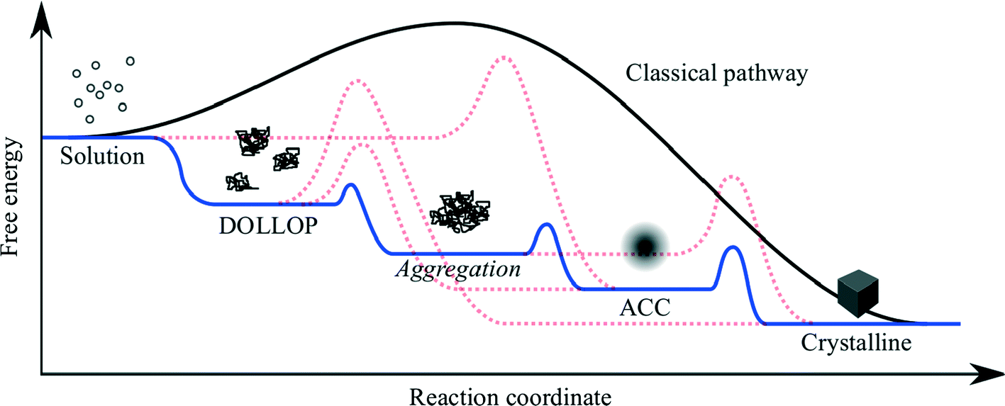 | ||
| Fig. 1 Schematic showing the free energy variation for a variety of possible pathways for crystallisation from ions in solution. DOLLOP (Dynamically Ordered Liquid-Like Oxyanion Polymer) refers to the prenucleation clusters identified in ref. 3, (image courtesy of R. Darkins). | ||
Recently there has been much discussion about non-classical nucleation,5 which is generally taken to mean that nucleation occurs via the aggregation of small clusters, rather than by the addition of single ions or formula units to a sub-critical cluster. The aggregating clusters may be amorphous (ACC in the figure) or crystalline. In the former case the amorphous clusters may undergo an amorphous to crystalline transition when the cluster reaches a critical size. The latter process is referred to as oriented attachment and this can result in the formation of mesocrystals,6 which are single crystals that retain some internal structure related to the subunits from which the macroscopic crystal is formed.
The possible mechanisms and pathways for crystallisation on substrates are more numerous and complex than those available to homogeneous nucleation (Fig. 2). Analogous to classical nucleation in a homogeneous solution, a critical cluster may form on the substrate and grow by ion addition.7 Amorphous clusters may form in solution and undergo an amorphous to crystalline transition after coming into contact with the substrate. The amorphous clusters may aggregate on the substrate, or form a continuous amorphous film, and then transform to a single crystal or polycrystalline film.8 In a process analogous to oriented attachment in bulk solution, small crystalline clusters may nucleate on the substrate and then aggregate all over the substrate through a diffusion mechanism.
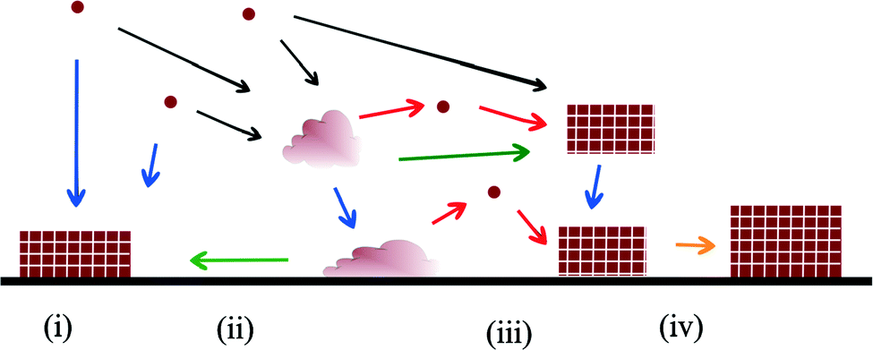 | ||
| Fig. 2 Schematic showing various crystallisation mechanisms on surfaces. Circles represent ions, rectangles represent crystals and irregular shapes represent an amorphous phase. (i) shows crystal nucleation on the substrate followed by ion-by-ion addition. (ii) shows an amorphous cluster forming in solution followed by deposition on the substrate and an amorphous to crystalline transition (green arrows). In (iii) the amorphous cluster on the substrate crystallises via dissolution and re-precipitation. (iv) represents crystal growth via oriented attachment (yellow arrow). | ||
In the next section we will review the experimental data in support of all the various mechanisms for crystallisation on organic substrates and the influence that substrates have on crystal polymorph and orientation. We will then review the theory and modelling techniques that have been used to study crystallisation on ordered organic substrates and the contribution these methods are making to the understanding of the influence of organic substrates on crystallisation processes.
3 The experimental position
There have been several major reviews on the experimental work on the use of monolayers to control crystal growth. Fricke and Volmer2 have discussed the work on calcium carbonate in detail. Song and Cölfen1 consider a number of systems in the context of additive control of crystal growth. We therefore shall summarise only the major points here. Most work has considered that the ability of organic monolayers to control crystal growth should be explained as some kind of templating effect. Early work9 used Langmuir monolayers as the templating agent for crystallisation. Since it was initially assumed that epitaxial matching was an essential part of the templating mechanism, the great flexibility of these layers to change their lattice parameters (provided this did not require great compression) was a perceived advantage. The degree of orientational control, however, is fairly low. Stripe et al.10 have used mixed monolayers to suggest that it is the average templating lattice that matters, not a detailed stereochemical fit. They find no effect of molecular tilt angle. Work from Volkmer and co-workers on Langmuir monolayers2,11 emphasized the importance of the charge density at the monolayer surface rather than epitaxial matching in controlling which phase of calcium carbonate is formed. The role of pre-nucleation clusters has been emphasized, with cryo-TEM suggesting that the initial stages of formation of CaCO3 on monolayers12 involves such species. Aggregation of prenucleation clusters has also been observed in the crystallization of calcium phosphate.13A detailed review of the preparation and use of self assembled monolayers (SAMs) is given in ref. 14. Most of the SAMs used in mineral  crystallisation are deposited on gold or silver substrates, most commonly on the Au (111) surface, using thiolates. For a high-coverage thiol array, the bonding habit is usually where the sulphur atoms are in the hollows of the gold lattice. The perfect surface unit cell of the alkane chains then has the symmetry c(4 × 2). The alkane chains are nearly all in the trans configuration and the chain is tilted, typically at a canting angle (α) of 30° and rotation angle (β) of 50° (see Fig. 3 for definitions). In practice, SAMs contain defects. These can be caused by metal defects in the substrate, grain boundaries or steps. Complex phase changes are possible with the introduction of gauche conformers into the system. Also, particularly for short chain lengths, the SAM can be disordered. In the simulations that we shall discuss, these complications are ignored since they usually occur on larger length-scales than those attainable by atomistic simulation. Their presence, however, should be considered when comparing with experiment.
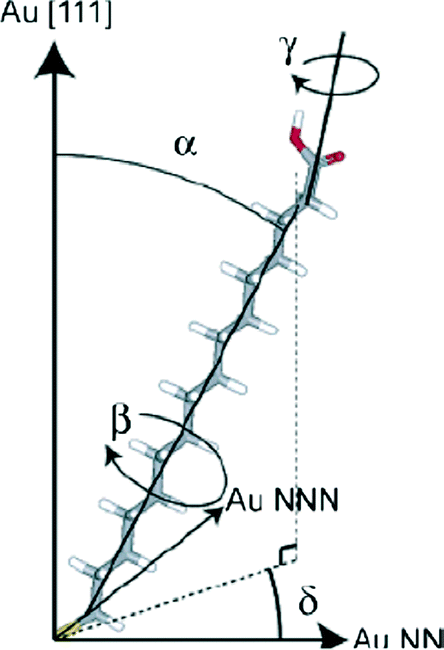 | ||
| Fig. 3 16-Mercaptohexadecanoic acid (MHA) and its degrees of freedom. The carboxylic acid endgroup is free to rotate about γ. Reprinted with permission from A. M. Travaille, L. Kaptijn, P. Verwer, B. Hulsken, J. A. A. W. Elemans, R. J. M. Nolte and H. van Kempen, J. Amer. Chem. Soc., 2003, 125, 11571.43©2003 American Chemical Society. | ||
Studies of crystallisation of calcium carbonate on SAMs15 demonstrated that epitaxial matching was not necessary for orientational control. Aizenberg et al.15 also demonstrated that some functional groups (OH, COO− and SO32−) give strong orientational control whereas others (PO32−) do not. Methyl termination, indeed, inhibits crystallisation. When solutions are replaced by an agarose gel16 the SAM still controls the orientation, but the aspect ratio (ratio of length to width) is reduced – probably a consequence of the incorporation of agarose fibres into the crystal. The use of monocrystalline mica substrates can increase the orienting effect of SAMs by suppressing the microdomain structure of the gold films evaporated onto them, producing a SAM that is ordered over long distances.17 Moreover, the observed control is different from that seen for Langmuir monolayers. In that case orientation in the (100) and (001) directions was observed.18 These authors ascribed these effects to the symmetry of the functional head-group.
Most of the studies on crystallisation (like those cited above) have used calcium carbonate. However, a number of other minerals have been considered including strontium carbonate,19 zinc oxide,20 barium sulphate,21 calcium phosphate,22 hydroxyapatite23 and hydrated iron oxides (lepidocrocite24 and goethite25). For a discussion of the use of SAMs to control the crystallisation of organic molecules, see the review of Singh et al.26
The length of the alkane chain can affect many properties of SAMs. Of particular importance are the so-called “odd–even” effects – the observation that SAMs with carbon chains having an odd number of carbon atoms (–S–C2n+1COO−) have different structures or properties to those with chains having an even number of carbon atoms (–S–C2nCOO−). A full review of the extensive literature can be found in.27 Our particular concern is how the alternation between odd and even SAMs can affect the ability of a SAM to control the crystallisation profoundly. Aizenberg and coworkers28 have observed that SAMs with an odd number of carbons in the chains (hereafter denoted odd SAMs) have a strong orientating effect, producing crystallisation in the (012) nucleating plane. On the other hand, even SAMs have a much weaker orienting effect and, if nucleation is observed, it tends to be in the (11m) plane where m is about three. OH functional groups can stabilise the amorphous phase.29 In the presence of free water, this transforms to calcite through a dissolution–reprecipitation mechanism. A more controllable transformation can be achieved using a SAM with carboxylate functional groups. Foreign molecules and ions can be introduced into the amorphous calcium carbonate (ACC) and some become incorporated into the crystalline calcite. It has been suggested that this can be used to make nanostructures using complex patterned quasi-2D systems.30
Direct effect of the solution can also affect the crystallisation. Aizenberg and co-workers31 point out that the order in which the calcium and carbonate containing solutions are added determines the efficacy of the monolayer – adding the calcium solution first greatly strengthens the orientating effect. Different concentrations of calcium ion affect the size, shape and orientation of calcite crystals on carboxylate monolayers.32 On alcohol terminated monolayers, low concentrations of calcium give vaterite, whereas high concentrations give calcite rhombs in the standard (104) nucleating plane.
A considerable body of work has emphasised the importance of monolayer flexibility for both Langmuir monolayers and SAMs. Popescu et al.33 have prepared a set of Langmuir monolayers where they have systematically changed the density of the surfactant monolayers. Although all the monolayers can nucleate calcite, only those that are flexible enough to allow the rearrangement of the molecules can affect the morphology. Lee et al.34 have prepared SAMs of varying flexibility by using mercaptodecyl benzoic acids with different placing of the functional carboxylate group on the aryl ring with respect to the alkyl chain. Only the para case produces oriented growth. This is the configuration that shows by far the greatest flexibility due to the reduced hydrogen bonding of this isomer.35 The crystal and monolayer (in effect) template one another to find the most stable interfacial structure; this is so-called cooperative crystallisation.
4 Modelling studies
The gulf between the timescales that can be modelled by atomistic simulations (nanoseconds) and the timescales required for nucleation (minutes to hours) generally inhibits the direct simulation of nucleation events. Understanding can, however, be greatly enhanced by employing simulation methods to calculate relevant interfacial and surface energies. Accelerated modelling methods, such as metadynamics for exploring nucleation pathways36 and Kinetic Monte Carlo methods for modelling growth,37 have also contributed much to the understanding of the fundamental mechanisms. Here we present the modified CNT for heterogeneous nucleation to highlight the relevant interfacial energies that can be calculated using atomistic simulations. We then present a review of the high temperature molecular dynamics and metadynamics simulations that have been used to model crystallisation of amorphous calcium carbonate on self-assembled monolayers.4.1 Classical theory of heterogeneous nucleation
The effect of a substrate on the nucleation of a solid from a fluid can be understood in terms of CNT (see, for example, Liu et al.7). The free energy change (ΔG) due to the formation of a nucleus of volume Vs in a bulk fluid is: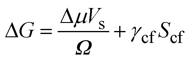 | (1) |
Here Δμ is the chemical potential, Ω is the atomic volume, γcf is the crystal/fluid interfacial free energy and Scf is the surface area of the crystal nucleus. For nucleation on a substrate we need to adjust the interfacial energy term to take account of the part of the crystal that is in contact with the substrate:
 | (2) |
Here γsc is the substrate/crystal interfacial free energy, γsf is the substrate/fluid interfacial free energy and Ssc is the area of the crystal in contact with the substrate. When the nucleus is a spherical cap, the position of intersection of the sphere with the surface (the cosine of the contact angle, m) is related to the ratio of the difference between the surface/crystal and surface/fluid interfacial free energies to the crystal/fluid interfacial free energy.
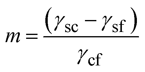 | (3) |
m is close to +1 for crystals that bind strongly to the substrate, in which case the cluster will be thin with a low contact angle. For weak crystal/surface interactions, m is close to −1 and the spherical cluster just touches the surface, resulting in a heterogeneous nucleation rate close to the homogeneous nucleation rate. The ratio of the heterogeneous to homogenous nucleation barriers, and thus the nucleation rate, increases with increasing m. The case of facetted clusters is more complex as the crystal/fluid area is a function, not only of the height of the nucleus above the surface, but also of the orientation of the crystal facet in contact with the substrate. Travaille et al.38 have calculated the contact area for different ranges of the interfacial energies for the particular case of calcite with a {012} surface in contact with the substrate and low energy {104} surfaces in contact with the fluid. They demonstrated that the spherical cap approximation was reasonable, at least for this particular case.
Under certain conditions the enthalpic components of the interfacial free energies in eqn (2) and (3) (γcf, γsc, γsf) can be calculated from atomistic simulations. This is straight forward when the substrate is the surface of a 3-dimensional material as the interfacial free energy (γsc) is defined uniquely as:
| γsc = γc + γs + βsc | (4) |
Here γc and γs are the surface free energies of the crystal and substrate respectively and βsc is the interfacial binding free energy, which is the free energy (per unit area) gained by joining the crystal and the substrate. βsc is, generally, negative and large negative values are representative of strong interactions between the crystal and the substrate. In the case where the substrate is a monolayer this definition is invalid as we cannot define the surface energy of the monolayer – the monolayer is already a surface. However if we consider only the difference between the interfacial free energies γsc − γsf the problematic monolayer surface energy cancels. We can, therefore, express m in terms of well-defined parameters.
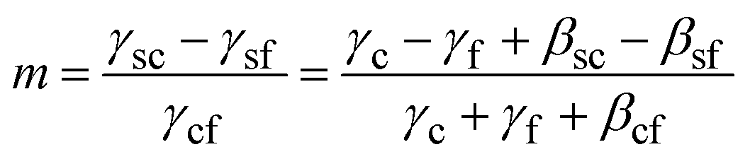 | (5) |
The enthalpic component of the surface and interfacial binding free energies can be calculated using molecular dynamics,39 at least when the surfaces are charge neutral and there is good epitaxial match between the substrate and the crystal. Complications arise when we consider polar crystal surfaces nucleating on ionised substrates. In the absence of reconstruction or neutralising species, the separated crystal and substrate have infinite energy so the challenge is then to obtain a meaningful definition of the interfacial energy that corresponds to the parameter that is relevant to the nucleation event. If we assume that the reference state (before the formation of the nucleus) is the Ca2+ and CO32− ions in solution with sufficient Ca2+ ions adsorbed on the substrate to neutralise the charge, we can determine the interfacial energy by calculating the surface energy of the polar surface by reducing the charge density of the outer layer of the slabs by half,40 thereby quenching the dipole.41
From a modelling perspective, the computational surface unit cell of the substrate and the crystal must be identical, therefore any lattice mismatch must be accommodated by adjusting the surface lattice parameters of the crystal, the substrate, or both. The induced strain energy can be cancelled by calculating the bulk reference energies using the same computational cells. For large lattice mismatch the misfit can be accommodated by line defects or misfit dislocations and, again, overall charge neutrality must be maintained. In the case of calcium carbonate it is possible that bicarbonate ions may play a role in charge neutralisation.42
In general, the symmetry of the crystal surface will not be the same as the substrate, therefore the epitaxial match will be better in some directions than others. Experimentally, this anisotropic epitaxial mismatch results in the growth of elongated crystals (Fig. 4).43 Indeed more mature crystals grow off the substrate such that the area in contact with the substrate remains constant as the crystal grows. This suggests that at some point during the growth, the unfavourable epitaxial strain energy dominates the favourable substrate/crystal energy. Pokroy and Aizenberg44 modelled this effect by extending the Hartman–Perdok growth model45 with an additional strain energy term to take account of misfit strain. As the misfit strain is, in general, anisotropic; the growth rates in different directions will be different, resulting in elongated crystals. Pokroy et al. calculated the differential growth rate by considering the strain to be accommodated by elastic deformation of the crystal and substrate. Large mismatch or large interfacial area would, however, induce excessive strains therefore one might expect the misfit to be accommodated by defects such as misfit dislocations. These dislocations would also cost energy and result in the same anisotropic growth as that predicted by the elastic strain model and, indeed, result in a reduced footprint on the substrate.46 Modelling the interface with the growing crystal raises further questions as the state of the system before crystallisation is generally unknown – i.e. are intermediates present at the interface? Simulations have attempted to calculate the interfacial energy with different disordered calcium carbonate structures47 showing a potential preference for particular SAM structures.
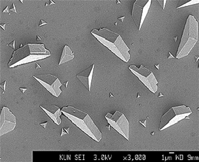 | ||
| Fig. 4 Calcite crystals grown on a SAM of MHA. Note the elongation of the more mature crystals. Reprinted with permission from A. M. Travaille, L. Kaptijn, P. Verwer, B. Hulsken, J. A. A. W. Elemans, R. J. M. Nolte and H. van Kempen, J. Amer. Chem. Soc. 2003, 125, 11571.43©2003 American Chemical Society. | ||
In summary, atomistic modelling can contribute to the understanding of nucleation and growth on substrates through the calculation of the various interfacial energies associated with the free energy barrier and critical nucleus. These do not provide absolute nucleation rates but they can be used to predict which crystal faces will be favoured on particular substrates.
4.2 High temperature molecular dynamics
Modelling the interfacial interactions and energies is one method available to computer simulation. More recently, to understand the morphology control of organic substrates better, modellers have turned to direct simulation of the crystallisation process. By its very nature, crystallisation will require the system to traverse a significant energy barrier, large enough to make it a rare event. These rare event processes are not seen in standard molecular dynamics where the timescale of the simulation (100 ns or less) does not generate a true time average of the system and allow for the necessary exploration of an entire energy surface. Therefore it is essential for modellers to devise methods to accelerate the exploration of the energy surface. A range of methods exist48 – mostly these involve some form of path sampling where the simulation is forced to remain close to a particular route by an energy biasing. This process can be very effective but only when that pathway is already reasonably well characterised. Unfortunately the actual atomic process of crystallisation is poorly understood and this type of path sampling could potentially dramatically alter the actual process that we wish to sample. Therefore methods that require less specific biasing of the simulation are needed.The most obvious mechanism to push a simulation over an energy barrier associated with crystallisation is to increase the temperature and hence the energy in the system. Duffy and Harding demonstrated this approach for CaCO3 on the SAM system.49 Although this approach works in many inorganic systems, increasing the temperature has the drawback that the monolayer molecules must be frozen as their structure will not survive the high temperatures. The simulations used a melted CaCO3 cluster on charged odd and even monolayers. The cations and anions could clearly be seen ordering into layers of alternating charge. Within these layers some further ordering could be observed particularly on the even monolayer with the radial distribution function suggesting a calcite-like structure being formed and with a (001) surface. Further analysis of this temperature-based crystallisation50 confirmed the (001) surface. Artificial rearrangement of the head-groups was performed and it was found that the only way to induce a surface other than the (001) surface was to completely alter the organisation of the head-groups to match the (012) calcite surface (Fig. 5). These temperature-based simulations with frozen monolayers suggested that the predicted experimental structure of the monolayer that matches the (001) calcite surface so well was only able to induce the (001) calcite surface in disagreement with experimental results.
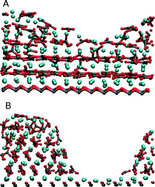 | ||
| Fig. 5 Shows the formation of the (A) (001) calcite and (B) (012) calcite surfaces depending on the selected frozen structure of the SAM. Figure reproduced with permission from C. L. Freeman, J. H. Harding and D. M. Duffy, Langmuir, 2008, 24, 9607.50©American Chemical Society. | ||
High temperature simulations have also been used to explore calcite crystallisation on calcite substrates and have suggested that the growth rates of calcite surfaces do not follow a simple pattern based on their surface energies.47,51 These results suggest that the growing crystal may have preferred orientations that will be sought out while in contact with the substrate.
4.3 Accelerated simulation methods
The two studies discussed in the previous section clearly highlighted that a frozen monolayer approach is not able to represent the crystallisation of calcite on the SAMs correctly. It could be expected that in many cases the flexibility and mobility of the organic substrate may play a crucial role in the crystallisation process. Therefore further methods that can include this have been explored.One methodology employed by Kawska et al.52 was to use a Monte Carlo type approach within a docking protocol. Ions are systematically added to a cluster and with each addition a range of potential sites is explored to identify the lowest energy addition. This whole system is then minimised before proceeding to the next addition. They utilised this methodology to explore calcium phosphate addition to an analogue of a collagen molecule.53 Exploring how this molecule influences the growth of calcium phosphate has obvious implications for bone development. This method does not actually encourage crystallisation and during the simulations only a small degree of order was observed to occur within the cluster formed. Without any actual direct encouragement of crystallisation the method remains largely restricted to analysing aggregation. This obviously may be a crucial step on the pathway to the final crystal.
Metadynamics54 is another methodology to tackle the issue of crystallisation. At its core, metadynamics defines a system by a series of order parameters, which for the case of crystallisation will be the spacing and orientation of the ions (i.e. structure factors). As the simulation runs, a record is kept of the order parameters for each configuration sampled and then a bias is applied to the system to encourage it not to return to these specific order parameter values. Via this approach the system is forced to explore more and more rare events, eventually leading to a crystallisation process. The clear advantage of this method is that it does not fundamentally force the system to follow a particular pathway nor does it alter the ensemble conditions (i.e. temperature). The simulation, is however, massively controlled by the choice of order parameter and the rate of biasing which must be carefully selected.
For organic substrate control this method was first used by Quigley et al.55 to model the crystallisation of calcite on SAMs. They considered a large matrix of different configurations varying the length of the monolayer chains, their ionisation and the presence of water molecules. Their simulations observed the formation of the (012) calcite surface on the even SAMs as experimentally reported which suggested in agreement with the earlier high temperature studies that the flexibility of the substrate was a crucial factor. Fig. 6 shows the results of metadynamics simulations of the crystallisation of ACC on an MHA SAM. When the substrate is frozen the crystal grows in the (001) orientation (Fig. 6a) whereas on the flexible substrate the (012) orientation is formed (Fig. 6b). In the (012) orientated structure, distortion of the SAM ensures localized areas of good match interspersed with areas of poor substrate/crystal epitaxy. We have recently shown that the (001) oriented structure has lower energy than the (012) structure, which indicates that kinetic factors dominate the orientation selection. Although metadynamics allows us to explore the system with a limited amount of biasing it still imposes important restrictions on our study. The bias within the simulation is applied to all the atoms of interest so all the Ca2+ and CO32− ions are being encouraged to order across the whole disordered cluster. Obviously crystallisation is generally a local event and not a global one but we are applying a global biasing. In addition, metadynamics is limited by its order parameters and therefore we must be able to design parameters that will sample what we need, which can be challenging.
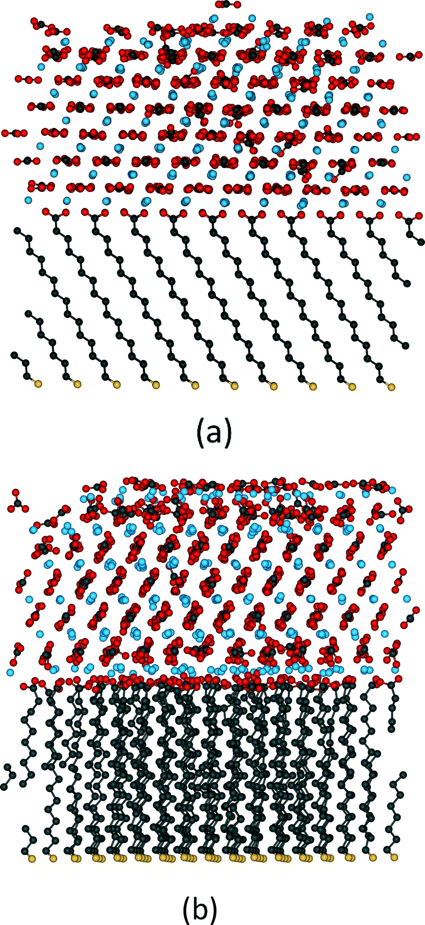 | ||
| Fig. 6 Structures formed by the crystallisation of ACC on MHA SAMs using metadynamics. In (a) the SAM is frozen and the crystal forms in the (001) orientation, whereas in (b) the substrate molecules are free to move and the crystal forms in an (012) orientation (image courtesy of A. S. Côté and A. Travis). | ||
5 Summary and conclusions
Much effort (both theoretical and experimental) has been put into understanding how self-assembled monolayers can control crystallisation. This is both because these systems have been considered as model systems for biomineralisation and in their own right as nanostructures and the foundation of nanostructures. The ability to make SAMs that contain patterns of different head-groups suggests that it is possible to grow complex structures and composites by careful design of the substrate – ensuring that different regions of the substrate promote the growth of different orientations or polymorphs of a given material or even different materials. A limitation on the structures produced has been the imperfections found in the monolayer, whether produced by defects in the underlying metal substrate or disorder in the monolayer itself. Although most work has been done on calcium carbonate, it is clear that the process is applicable to a wide range of minerals and also to organic molecules. This is also known in biological systems, in particular the formation of nacre.Ideas concerning the mechanism have changed considerably with contributions from both simulation and experiment. The original suggestion that control was due to epitaxial matching proved to be far too simple, neglecting the fact that an interface involving a flexible substrate allows many possibilities of evading the requirements of strict geometrical epitaxy. Moreover, the best epitaxial match need not be the interface that is the most stable. This is shown by the rarity of formation of the (001) orientation – which has an excellent epitaxial match – compared to the (012) orientation where the epitaxial matching is much poorer. Considerations of electrostatics are, however, important as Volkmer and coworkers2,11 have argued from the experimental data on the systems they have studied and as simulations have born out.
Much work remains to be done on the mechanism of formation. It is clear that an amorphous phase is part of the process of formation. However whether the crystalline phase is obtained by direct transformation or by a dissolution–reprecipitation mechanism depends on circumstances. If direct transformation occurs, there is the further question of how and when the water is removed from the amorphous phase (which is always hydrated, at least initially) to produce the anhydrous vaterite, aragonite or calcite phases. Also, where direct transformation occurs, if the cation or anion is highly asymmetric (as is the case for calcium carbonate), the initial distribution of the orientation of the asymmetric ion can play an important part in determining the final morphology of the growing crystal.
Since so much of the experimental work has been done on the calcium carbonate system, an important question is how specific the conclusions are to that material. As noted above, studies have been performed on other systems but to nothing like the same extent as for calcium carbonate. Also, calcium carbonate remains the only system where extensive simulations have been performed. In this system, close collaboration between experimentalists and simulators has enabled a detailed picture to be developed of the role of SAMs in controlling crystal orientation. However, if SAMs are to fulfil their potential for applications, there needs to be more work to see whether the lessons learned from this (comparatively) well-understood system are applicable more generally.
Acknowledgements
This work was supported by the UK Engineering and Physical Sciences Research Council [grant number EP/I001514/1]. This Programme Grant funds the Materials Interface with Biology (MIB) consortium. Via our membership of the UK's HPC Materials Chemistry Consortium, which is funded by EPSRC (EP/F067496), this work made use of the facilities of HECToR, the UK's national high-performance computing service, which is provided by UoE HPCx Ltd at the University of Edinburgh, Cray Inc and NAG Ltd, and funded by the Office of Science and Technology through EPSRC's High End Computing Programme.References
- R.-Q. Song and H. Cölfen, CrystEngComm, 2011, 13, 1249 RSC.
- M. Fricke and D. Volmer, Top. Curr. Chem., 2007, 270, 1 CrossRef CAS.
- R. Demichelis, P. Raiteri, J. D. Gale, D. Quigley and D. Gebauer, Nat. Commun., 2011, 2, 590 CrossRef PubMed.
- W. J. E. M. Habraken, J. Tao, L. J. Brylka, H. Friedrich, L. Bertinetti, A. S. Schenk, A. Verch, V. Dmitrovic, P. H. H. Bomans, P. M. Frederik, J. Laven, P. van der Schoot, B. Aichmayer, G. de With, J. J. DeYoreo and N. A. J. M. Sommerdijk, Nature Comm., 2013, 4, 1507 CrossRef PubMed.
- D. Erdemir, A. Y. Lee and A. S. Myerson, Acc. Chem. Res., 2009, 42, 621 CrossRef CAS PubMed; D. Gebauer, A. Volkel and H. Cölfen, Science, 2008, 322, 1819 CrossRef PubMed; J. J. de Yoreo, Nat. Mater., 2013, 12, 284 CrossRef PubMed; D. Kashchiev, P. G. Vekilov and A. B. Kolomeisky, J. Chem. Phys., 2005, 122, 244706 CrossRef PubMed; B Mutaftschiev, The atomistic nature of crystal growth, Springer-Verlag, 2001 CrossRef PubMed; S. Whitlam, J. Chem. Phys., 2010, 132, 94901 CrossRef PubMed; D. Gebauer and H. Cölfen, Nano Today, 2011, 6, 564 CrossRef PubMed.
- H. Cölfen and M. Antonietti, Angew. Chem., Int. Ed., 2005, 44, 5576 CrossRef CAS PubMed; J. Fang, B. Ding and H. Cölfen, Chem. Soc. Rev., 2011, 40, 5347 RSC; R.-Q. Song and H. Cölfen, Adv. Mater., 2012, 22, 1301 CrossRef PubMed.
- X. Y. Liu and S. W. Lim, J. Am. Chem. Soc., 2003, 125, 888 CrossRef CAS PubMed; J. J. De Yoreo and P. Vekilov, Principles of crystal nucleation and growth, in Biomineralization., ed. P. M. Dove, J. J. de Yoreo and S. Weiner, Mineral Soc Am, Washington, DC, 2003, pp. 57–93 Search PubMed.
- A. Dey, G. de With and N. A. J. M. Sommerdijk, Chem. Soc. Rev., 2010, 39, 381 RSC.
- B. R. Heywood and S. Mann, Chem. Mater., 1994, 6, 311 CrossRef CAS.
- B. Stripe, S. Uysal, B. Lin, M. Meron and P. Duttaz, Langmuir, 2012, 28, 572 CrossRef CAS PubMed.
- F. F. Amos, D. M. Sharbaugh, D. R. Talham, L. B. Gower, M. Fricke and D. Volkmer, Langmuir, 2007, 23, 1998 CrossRef CAS PubMed ; M. Fricke, D. Volkmer, C. E. Krill III, M. Kellermann and A. Hirsch, Cryst. Growth Des., 2006, 6, 1120 Search PubMed.
- E. M. Pouget, P. H. H. Bomans, J. A. C. M. Goos, P. M. Frederik, G. de With and N. A. J. M. Sommerdijk, Science, 2009, 323, 1455 CrossRef CAS PubMed.
- A. Dey, P. H. H. Bomans, F. A. Müller, J. Will, P. M. Frederik, G. de With and N. A. J. M. Sommerdijk, Nat. Mater., 2010, 9, 1010 CrossRef CAS PubMed.
- J. C. Love, L. A. Estroff, J. K. Kriebel, R. G. Nuzzo and G. M. Whitesides, Chem. Rev., 2005, 105, 1103 CrossRef CAS PubMed.
- J. Aizenberg, A. J. Black and G. M. Whitesides, J. Am. Chem. Soc., 1999, 121, 4500 CrossRef CAS.
- H. Li and L. A. Estroff, J. Am. Chem. Soc., 2001, 129, 5460 Search PubMed.
- A. M. Travaille, J. J. J. M. Donners, J. W. Gerritsen, N. A. J. M. Sommerdijk, R. J. M. Nolte and H. van Kempen, Adv. Mater., 2002, 14, 492 CrossRef CAS.
- S. Mann, B. R. Heywood, S. Rajam and J. B. A. Walker, J. Phys. D: Appl. Phys., 1991, 242, 154 CrossRef CAS ; B. R. Heywood and S. Mann, Chem. Mater., 1994, 6, 311 CrossRef.
- J. Kuther, G. Nelles, R. Seshadri, M. Schaub, H. J. Butt and W. Tremel, Chem.–Eur. J., 1998, 4, 1521 CrossRef.
- J. W. P. Hsu, M. W. Clift and L. N. Brewers, Langmuir, 2008, 24, 5375 CrossRef CAS PubMed.
- H. Eun and Y. Amasuma, Anal. Chim. Acta, 1998, 375, 155 CrossRef CAS.
- Q. Liu, J. Ding, F. K. Mante, S. L. Wunder and G. R. Baran, Biomaterials, 2002, 23, 3103 CrossRef CAS.
- D. P. Liu, P. Majewski, B. K. O'Neill, Y. Ngothai and C. B. Colby, J. Biomed. Mater. Res., Part A, 2006, 77, 763 CrossRef CAS PubMed.
- M. Nagtegaal, P. Stroeve and W. Tremel, Thin Solid Films, 1998, 327, 571 CrossRef.
- B. J. Tarasevich, P. C. Rieke and J. Liu, Chem. Mater., 1996, 8, 292 CrossRef CAS.
- A. Singh, I. S. Lee, K. Kim and A. S. Myerson, CrystEngComm, 2011, 13, 24 RSC.
- F. Tao and S. L. Bernasek, Chem. Rev., 2007, 107, 1408 CrossRef CAS PubMed.
- Y. J. Han and J. Aizenberg, Angew. Chem., Int. Ed., 2003, 42, 3668 CrossRef CAS PubMed.
- T. Y.-J. Han and J. Aizenberg, Chem. Mater., 2008, 20, 1064 CrossRef CAS.
- J. Aizenberg, D. A. Muller, J. L. Grazul and D. R. Hamann, Science, 2003, 299, 1205 CrossRef CAS PubMed.
- J. Aizenberg, A. J. Black and G. M. Whitesides, J. Am. Chem. Soc., 1999, 121, 4500 CrossRef CAS.
- H. Deng, X.-M. Wang, C. Du, X.-C. Shen and F.-Z. Cui, CrystEngComm, 2012, 14, 6647 RSC.
- D. Popescu, M. M. J. Smulders, B. P. Pichon, N. Chebotareva, S.-Y. Kwak, O. L. J. van Asselen, R. P. Sijbesma, E. DiMasi and N. A. J. M. Sommerdijk, J. Am. Chem. Soc., 2007, 129, 4058 CrossRef PubMed.
- J. R. I. Lee, T. Y.-J. Han, T. M. Willey, D. Wang, R. W. Meulenberg, J. Nilsson, P. M. Dove, L. J. Terminello, T. van Buuren and J. J. De Yoreo, J. Am. Chem. Soc., 2007, 129, 10370 CrossRef CAS PubMed.
- A. S. Côté, C. L. Freeman, R. Darkins and D. M. Duffy, J. Phys. Chem. C, 2013, 117, 7148 Search PubMed.
- D. Quigley, C. L. Freeman, J. H. Harding and P. M. Rodger, J. Chem. Phys., 2011, 134, 044703 CrossRef CAS PubMed.
- J. M. McCoy and J. P. LaFemina, Surf. Sci., 1997, 373, 2889 CrossRef CAS ; R. E. Williford, D. R. Baer, J. E. Amonette and A. S. Lea, J. Cryst. Growth, 2004, 262, 503 CrossRef PubMed.
- A. M. Travaille, E. G. A. Steijven, H. Meekes and H. van Kempen, J. Phys. Chem. B, 2005, 109, 5618 CrossRef CAS PubMed.
- D. M. Duffy and J. H. Harding, Langmuir, 2004, 20, 7630 CrossRef CAS PubMed.
- D. M. Duffy and J. H. Harding, Langmuir, 2004, 20, 7637 CrossRef CAS PubMed.
- P. W. Tasker, J. Phys. C: Solid State Phys., 1979, 12, 4977 CrossRef CAS.
- D. M. Duffy, A. M. Travaille, H. van Kempen and J. H. Harding, J. Phys. Chem. B, 2005, 109, 5713 CrossRef CAS PubMed.
- A. M. Travaille, L. Kaptijn, P. Verwer, B. Hulsken, J. A. A. W. Elemans, R. J. M. Nolte and H. van Kempen, J. Am. Chem. Soc., 2003, 125, 11571 CrossRef CAS PubMed.
- B. Pokroy and J. Aizenberg, CrystEngComm, 2007, 9, 1219 RSC.
- P. Hartman and W. G. Perdok, Acta Crystallogr., 1955, 8, 49 CrossRef.
- C. R. Henry, Prog. Surf. Sci., 2005, 80, 92 CrossRef CAS PubMed.
- C. L. Freeman, Q. Hu, M. H. Nielsen, J. Tao, J. J. De Yoreo and J. H. Harding, J. Phys. Chem., 2013, 117, 5154 CAS.
- Examples include: Umbrella sampling, G. M. Torrie and J. P. Valleau, J. Comput. Phys., 1977, 23, 187 CrossRef , Temperature accelerated dynamics: A. R. Sorensen and A. F. Voter, J. Chem. Phys., 2000, 112, 9599 CrossRef , Parallel Tempering: R. H. Swendsen and J. S. Wang, Phys. Rev. Lett., 1986, 198657, 2607 CrossRef.
- D. M. Duffy and J. H. Harding, Surf. Sci., 2005, 595, 151 CrossRef CAS PubMed.
- C. L. Freeman, J. H. Harding and D. M. Duffy, Langmuir, 2008, 24, 9607 CrossRef CAS PubMed.
- R. Darkins, A. S. Cote, C. L. Freeman and D. M. Duffy, J. Cryst. Growth, 2013, 367, 110 CrossRef CAS PubMed.
- A. Kawska, J. Brickmann, R. Kniep, O. Hochrein and D. Zahn, J. Chem. Phys., 2006, 124, 024513 CrossRef PubMed.
- A. Kawska, O. Hochrein, J. Brickmann, R. Kniep and D. Zahn, Angew. Chem., Int. Ed., 2008, 47, 4982 CrossRef CAS PubMed.
- A. Laio and M. Parrinello, Proc. Natl. Acad. Sci. U. S. A., 2002, 99, 12562 CrossRef CAS PubMed.
- D. Quigley, P. M. Rodger, C. L. Freeman, J. H. Harding and D. M. Duffy, J. Chem. Phys., 2009, 131, 094703 CrossRef CAS PubMed.
| This journal is © The Royal Society of Chemistry 2014 |