Enzymatic filter for improved separation of output signals in enzyme logic systems towards ‘sense and treat’ medicine†
Shay
Mailloux
a,
Oleksandr
Zavalov
a,
Nataliia
Guz
a,
Evgeny
Katz
a and
Vera
Bocharova
*b
aDepartment of Chemistry and Biomolecular Science, Clarkson University, Potsdam, NY 13699-5810, USA
bChemical Sciences Division, Oak Ridge National Laboratory, Oak Ridge, Tennessee 37830-6197, USA. E-mail: bocharovav@ornl.gov; Fax: +1-(865)5744961; Tel: +1-(865)576-6490
First published on 17th October 2013
Abstract
The major challenge for the application of autonomous medical sensing systems is the noise produced by non-zero physiological concentrations of the sensed target. If the level of noise is high, then a real signal indicating abnormal changes in the physiological levels of the analytes might be hindered. Inevitably, this could lead to wrong diagnostics and treatment, and would have a negative impact on human health. Here, we report the realization of a filter system implemented to improve both the fidelity of sensing and the accuracy of consequent drug release. A new filtering method was tested in the sensing system for the diagnosis of liver injury. This sensing system used the enzymes alanine transaminase (ALT) and aspartate transaminase (AST) as the inputs. Furthermore, the output of the sensing system was designed to trigger drug release, and therefore, the role of the filter in drug release was also investigated. The drug release system consists of beads with an iron-cross-linked alginate core coated with different numbers of layers of poly-L-lysine. Dissolution of the beads by the output signals of the sensing system in the presence and absence of the filter was monitored by the release of rhodamine-6G dye encapsulated in the beads, mimicking the release of a real drug. The obtained results offer a new view of the problem of noise reduction for systems intended to be part of sense and treat medical devices.
Introduction
Recently, chemical1–6 and biochemical7–12 systems, utilizing built-in binary logic capable of processing chemical,3 biochemical13 or physical14 signals, have received strong interest. They offer unique features such as broad tuning capability and a variety of designs, making them suitable for many practical applications. The ability of such systems to be tuned by changing the concentrations of different elements allows processing of the data in the form of different logic gates1,2 such as AND, OR, etc. In biomedical applications, digitalization of biochemical signals for systems based on enzymes,15,16 DNA,17,18 RNA,19 and whole cells20–23 has already been achieved. For example, it was shown that the signals from enzymatic cascades processed by various logic gates24 can be interpreted as logic-1 and logic-0 (‘yes’ and ‘no’) outputs.25,26 Since certain enzymes are biomarkers characteristic of various injuries and diseases, digitalization of the biochemical signal facilitates the realization of the concept of ‘smart’ biosensors capable of detecting a single disease27 and of differentiating the simultaneous presence of multiple diseases.28 Additionally, it has been demonstrated that a signal from an enzyme29,30 or an enzymatic cascade31 can be coupled via stimuli-responsive materials acting as drug release systems, thus promoting the application of biochemical systems for the fabrication of medical devices capable of autonomous sense and treat actions.In general, the major challenge for the practical application of medical sensing systems based on enzymes is the accumulation of the noise15 produced by non-zero physiological concentrations of sensing analytes. Distinguishing between a true biochemical signal corresponding to injury or disease and a high level of noise generated in the system is a complicated task. In the sensing stage, poor separation between logic-0 and logic-1 can perhaps be partially solved by establishing a threshold for noise electronically. The situation is different for systems where the output signal is directly coupled with the drug release systems. In such a case electronic adjustment of the signal will not eliminate its physical presence. In these specific systems, prolonged accumulation of the logic-0 output could lead to release of the drug even under healthy conditions.32,33 Solving the problem of built-up noise in these systems is crucial to avoid false diagnostics and unneeded medical treatment that may have lasting adverse effects on the individual's health.
Recently, the concept of biochemical34 and chemical35 filters has been employed to reduce the noise levels in biomedical analytical systems utilizing binary logic. A special feature of this approach has been that the integration of the filtering step with a digital gate process significantly improves the signal-to-noise ratio, transforming the convex shape of response for enzymatic cascade into a sigmoidal response.34–38 This behavior is particularly desired when using binary values 0 and 1 as an output response, corresponding to the normal physiological and pathophysiological concentration of biomarkers.36
In the present paper, for the first time, the concept of filter systems is implemented to improve not only the sensing capability of an enzymatic cascade but also to better control the release of a drug. In an attempt to sufficiently suppress the interfering logic-0 outputs from the enzymatic cascade, an enzymatic filter was incorporated into the biocatalytic cascade. The effect of the enzymatic filter on the fidelity of the signals processed in the biocatalytic cascade was evaluated for the sensing of liver injury. Effectiveness of the filter was tested on the drug release systems composed of an iron-cross-linked alginate core coated with different numbers of poly-L-lysine layers. Comparison between release mechanisms from the drug release system in the presence and absence of the filter is discussed.
Experimental methods
Chemicals and reagents
Alanine transaminase from porcine heart (ALT, E.C. 2.6.1.2), aspartate transaminase, type 1 (AST, E.C. 2.6.1.1), citrate synthase from porcine heart (CS, E.C. 2.3.3.1), malic dehydrogenase from porcine heart (MDH, E.C. 1.1.1.37), glutamic acid, pyruvic acid, aspartate sodium salt, acetyl coenzyme A sodium salt (acetyl CoA), β-nicotinamide adenine dinucleotide (reduced dipotassium salt) (NADH), 5,5′-dithiobis(2-nitrobenzoic acid) (DTNB), alginic acid sodium salt from brown algae (medium viscosity, ≥2000 cP), poly-L-lysine hydrobromide (mol. wt. 30![[thin space (1/6-em)]](https://www.rsc.org/images/entities/char_2009.gif) 000–70000), rhodamine-6G, and 3-(N-morpholino)propanesulfonic acid (MOPS buffer) were purchased from Sigma-Aldrich, J. T. Baker and Fisher Scientific and used as supplied without any pretreatment or further purification. Ultrapure water (18.2 MΩ cm) from a NANOpure Diamond (Barnstead) source was used in all of the experiments. The experiments were performed at ambient temperature, 25 °C ± 2 °C.
000–70000), rhodamine-6G, and 3-(N-morpholino)propanesulfonic acid (MOPS buffer) were purchased from Sigma-Aldrich, J. T. Baker and Fisher Scientific and used as supplied without any pretreatment or further purification. Ultrapure water (18.2 MΩ cm) from a NANOpure Diamond (Barnstead) source was used in all of the experiments. The experiments were performed at ambient temperature, 25 °C ± 2 °C.
Composition of the liver injury biocatalytic cascade
Glutamic acid (10 mM), pyruvic acid (5 mM), aspartate sodium salt (50 mM), acetyl CoA (5 mM), and citrate synthase (1 U mL−1) were dissolved in MOPS (20 mM), pH = 7.4, to form the “machinery” of the system. Logic-0 and 1 levels of ALT (0.02 and 2 U mL−1) and AST (0.02 and 2 U mL−1) which correspond to the normal and pathophysiological biomarker concentrations,39 respectively, were used as inputs, activating the cascade. The system acts as an AND gate, signaling liver injury when both inputs are at their logic-1 concentration. Either or both of the inputs at their logic-0 concentrations will produce a negative response. The production of citrate was measured using the 1:1 stoichiometry of the reaction of DTNB40,41 with a thiol group on the CoASH. In order to monitor the citric acid production kinetically, a reaction mix was monitored over a two hour time period with 10 μL aliquots removed periodically and combined with 10 μL of DTNB (0.1 mM) in a total volume of 1 mL diluted with buffer. The absorbance at 412 nm was used to calculate40,41 the concentration of CoASH produced, and so, indirectly, the citric acid produced in the system.
Composition of the liver injury biocatalytic cascade with applied enzymatic filter
The composition of the system was the same as the above section with MDH (1 U mL−1) and NADH (2 mM) dissolved in MOPS (20 mM), pH = 7.4, added to the machinery. Citric acid was monitored using the same method as above.Fabrication of rhodamine-6G – loaded alginate hydrogel microspheres
Sodium alginate was dissolved in water at 37 °C overnight to give a 1% (w/v) solution. 1.0 mL of alginate solution was then mixed with 198 μL (0.9 mg mL−1) of rhodamine-6G solution made in 20 mM MOPS buffer, pH 7.4. Rhodamine-6G was introduced to mimic the release of a drug molecule. The alginate–rhodamine solution was then sprayed through a 31-gauge needle forming droplets and pushed off the tip using compressed air. Airflow was adjusted to control the size of the droplet pushed off the needle. Upon contact with 1% (w/v) FeCl3 solution in deionized water the droplets formed alginate hydrogel spheres which were incubated in the cross-linking solution for 15 minutes. The spheres were then filtered out of the FeCl3 solution using gravity filtration and moved to a Petri dish where they were washed in water. The average size of the particles was 1 mm.LbL assembly of the alginate beads using poly-L-lysine and alginate
0.05% (w/v) of poly-L-lysine (PLL) was prepared in 20 mM MOPS buffer, pH 7.4 and alginate (0.5% w/v) was dissolved in deionized water. The Fe3+-alginate hydrogel beads were then immersed in each of these solutions. For one layer and multi-layer beads, PLL was deposited followed by a second layer of alginate, forming a PLL and alginate bi-layer (PLA). Spheres without PLL have only an alginate core. Each layering step proceeded for 5 minutes and the beads were washed with water in between depositions. The resulting beads were alginate hydrogels with Fe3+-cross-linked rhodamine-6G loaded core with coatings of electrostatically bound layers of PLA. In our experiments, beads with one, two and three layers of PLA were utilized. Beads with different PLA layers were visualized using a fluorescent confocal microscope. They were prepared using the method described above except that the PLL used in layering was FITC-labeled to give fluorescence at 525 nm. Additionally, because rhodamine-6G gives fluorescence at the same wavelength as FITC, the beads for confocal microscope were prepared without rhodamine-6G.Release of model drug from alginate beads and from multi-layer alginate beads
In order to measure release of the model drug from the beads, citric acid produced in the biocatalytic cascade was applied. Rhodamine-6G release was monitored by fluorescent spectroscopy at 550 nm. Background interferences were removed based on baseline obtained from dissolution of the beads without rhodamine-6G for each time-interval.Instrumentation and measurements
Fluorescent measurements were performed using a fluorescent spectrophotometer (Varian, Cary Eclipse). A Shimadzu UV-2450 UV-vis spectrophotometer, with a TCC-240A temperature controlled holder and 1 mL poly(methyl methacrylate) (PMMA) cuvettes, was used for all absorbance optical measurements. Confocal micrographs were taken using a Scanning Laser Confocal Fluorescence Microscope, Nikon Eclipse C1 (488 nm argon-ion laser was used) with 10x-CFI objective. Images from the confocal microscope were handled using EZ-C1 Software Version 3.10 (Nikon Corporation).Results and discussion
An iron-cross-linked alginate-based system suitable for triggered drug release was reported elsewhere.31 The system was shown to release a model drug in response to a specific chemical, citric acid. This chemical was generated in a biocatalytic cascade associated with liver injury. Depending on the input combinations the output signal of the system was processed as logic-0 (‘no’) or logic-1 (‘yes’) indicating the absence or presence of liver injury, respectively. In this system, separation of logic-1 and logic-0 outputs was achieved by tuning the concentrations of the components in the system. Although the biocatalytic cascade can separate the logic-0 and logic-1 outputs reasonably well within a short time range, long term monitoring without further modification is problematic. Furthermore, connecting the biocatalytic cascade with the drug release system for long term monitoring also becomes challenging mainly because of the accumulation of logic-0 signals over time due to the non-zero concentrations of input biomarkers corresponding to healthy conditions. Realization of this scenario will initiate drug release, giving false indications of the presence of the injury. This leads to the necessity of further optimization of the biocatalytic cascade to achieve suppression of logic-0 signals.The present study is focused on the improvement of the reliability of the output signals after introduction of the enzymatic filter into the biocatalytic cascade.
Scheme 1 shows the general composition and operation of the biocatalytic cascade that can either be used to sense the presence of liver injury if the TNB (2-nitro-5-thiobenzoic acid; product of enzymatic conversion of DTNB; see Scheme 1) output is analyzed or to initiate release of a drug from alginate beads with citric acid as the output. The purple square in Scheme 1 outlines the presence of the filter. For a detailed description of the system refer to ref. 31 and the Experimental section of the present paper. Briefly, two enzymes, alanine transaminase (ALT) and aspartate transaminase (AST), were selected as biomarkers signaling liver injury. Their simultaneous presence at elevated concentrations (combination 1,1) produced a logic-1 output related to the sensing of liver injury, where all other combinations were processed as logic-0 refuting the presence of this injury. Citric acid produced in the biocataytic cascade was used as a chemical signal to dissolve iron-cross-linked alginate beads. In the present study, malate dehydrogenase (MDH) was introduced into the system as a filter to regulate the production of citric acid. Particularly, this enzyme regulates the production of citric acid by partially removing oxaloacetate (Oxa) produced by AST in the biocatalytic cascade. The rate of conversion of oxaloacetate to malate (Mal) can be controlled by the concentrations of the enzyme and NADH. It is noteworthy, for the future utilization of this type of system for medical sensing and/or drug release, that the following parameters should be taken into account while tuning the biocatalytic cascade: maximal suppression of all logic-0 outputs and minimal changes in the logic-1 output. Concentrations of 1 U ml−1 of the filtering enzyme and 2 mM NADH were found satisfactory in achieving these conditions.
 | ||
| Scheme 1 The biocatalytic cascade mimicking the AND logic gate activated by two input signals, ALT and AST, which are biomarkers of liver injury. The production of citrate is indirectly analyzed by measuring the CoASH by-product using the DTNB-assay for thiol groups at 412 nm. The filtering effect in the system is introduced by the enzyme MDH. | ||
Fig. 1 depicts a bar diagram representing the production of citric acid in the biocatalytic cascade for the four input combinations with and without the filter at cut-off times of 40 and 120 min. The kinetics of the production of citric acid from the biocatalytic cascade for all input combinations in the presence (Fig. S1†) and absence (Fig. S2†) of the filter can be found in ESI.† For convenience, the performance of the filter was evaluated for two specific cases; however, the overall trend remains the same for any selected time pairs.
 | ||
| Fig. 1 Bar diagram represent the production of citric acid by the biocatalytic cascade with (red, green) and without (black, magenta) a filter for 40 min (black, red) and 120 min (magenta, green) after application of 4 different input combinations. | ||
The role of the filter is the initiation of the suppression of the production of citric acid for logic-0 and logic-1 outputs (Fig. 1). Interestingly, the degree of suppression increases as a function of time within the same output. For example, the production of citric acid by the 1,0 combination is suppressed almost 2 times for 40 min and 3.7 times for 120 min. This behavior can be explained by the nature of the filter itself. The rate of conversion in any enzymatic reaction depends on the concentrations of the substrates, typically increasing for a while before reaching a constant rate of conversion and, eventually, saturation. Thus, better suppression for a longer reaction time (where there is more substrate for the enzymatic filter) is expected for an enzyme-based filter. Notably, a rate of 3.7 is the maximal magnitude of suppression of the signal achieved within the present biocatalytic cascade. Unexpectedly, the production of citric acid for logic-1 was not significantly affected by the filter. This signal is approximately 1.2 times higher in the absence of the filter for both 40 and 120 min. The system itself has a very complex structure, with many dynamically changing variables affecting the production of citric acid. One of the possible explanations is that citrate synthase is inhibited by the high concentration of citrate42 produced by the 1,1 input combination. Citrate synthase can then be ‘reactivated’ in the presence of the filter, resulting in an increase in citric acid production. On the other hand, the working filter itself serves as a compensatory force, decreasing the production of citric acid, and thus the final concentration of citrate produced by the 1,1 combination remains unchanged. However, there are also other components in the system, such as NADH and NAD+, which might affect the activity of citrate synthase.43 Seemingly, the final concentration of citrate is a product of the interplay between the activation and inhibition of citrate synthase induced by different components of the system. The influence of each of these separate components requires further investigation.
To evaluate the diagnostic potential of the biocatalytic cascade with and without the addition of the filter a receiver operating characteristic analysis (ROC) was used.44–46 We have used this method previously to evaluate the diagnostic features of other biocatalytic systems.47 Typically, an ROC curve is created by analyzing the rate of true positives to positives and false positives to negatives at different threshold settings. In our case, the signals produced by physiological and pathophysiological levels of biomarkers for liver injury diagnosis in the human body39 were chosen as thresholds.
We collected two sets of data for the four logic combinations representing logic-0 and logic-1 values, limiting our selection from 60 to 120 min where “filtering” clearly separates the 0 and 1 outcomes. We did our analysis in terms of the logically scaled variables to minimize the time-dependent drift in the values by dividing the data by the average level of logic-1 fitted as a time-dependent curve to the output in logic-1. Note that the distribution of the output signals for use in real medical applications will be changed. Testing our system in all time points, we obtained two ROC curves (Fig. 2), which are drawn as plots of test sensitivity (the y coordinate) versus specificity or false positive rate (the x coordinate). The area under the ROC curve (AUC) is a common characteristic of the test, a measure of its accuracy, and a sign that it is highly probable that a randomly chosen diagnostic test will give us the correct answer.48 It allows the user to properly diagnose the condition relative to the normal or pathophysiological concentrations.44
 | ||
| Fig. 2 Receiver operating characteristic (ROC) curves for the enzymatic cascade with (red) and without (blue) the filter. Random choice is denoted by the green diagonal line. The sensitivity and specificity of the systems were calculated as an area under ROC curves (AUC). | ||
The AUC of the ROC curve for the system without the filter produces reliable results in 88% of cases (Fig. 2). On the other hand, tests carried out for the system with the inclusion of the filter allows a proper diagnostic result in 100% of cases. The ROC curve has an AUC of about 1.00 and, as a result, corresponds to 100% sensitivity and 100% specificity. Thus, the integration of the filter into the enzymatic cascade sufficiently increases the potential for this system to work as a diagnostic tool.
In addition to evaluating the enzymatic system in the presence of the filter as a standalone biomedical analytical tool for the detection of liver injury, we have also reviewed the possibility of utilizing filtered outputs of the system for triggering the dissolution of beads containing a model drug, specifically a rhodamine-6G dye. In this case, maximal concentrations of citric acid produced by 1,1 and 1,0 input combinations for the system with and without a filter were applied to dissolve uncoated and coated iron-cross-linked alginate beads containing the ‘drug’ within their cores. The 1,0 combination was selected because citric acid production is at its maximal point among all logic-0 values at this combination and is consistent with our previous results.31Fig. 3 shows the kinetics of the fluorescence increase at 550 nm from rhodamine-6G released from a single bead with no (A), one (B), two (C) and three (D) layers of PLA dissolved by citric acid produced by 1,0 and 1,1 input combinations in the biocatalytic cascade with and without the enzymatic filter.
 | ||
| Fig. 3 Kinetics of the release of rhodamine-6G from microbeads triggered by 1,0 and 1,1 input combinations in the presence (blue and magenta lines) and absence (black and red) of the filter for alginate (A), and alginate coated with one (B) layer, two (C) and three (D) layers of PLA. ΔAn-corresponds to normalized intensity. The release was measured at 550 nm by detecting the fluorescence intensity of rhodamine-6G over 2 hours. | ||
The shapes of the release curves are different for coated beads compared to beads without PLA layers. Major portions of the observation periods of release for a bead without PLA layers follow zero order kinetics with different rates of release for logic-0 and logic-1 outputs (Fig. 3A), and beads with PLA layers demonstrate both a sigmoidal pattern of release with a characteristic delay time and zero-order kinetics (Fig. 3B–D). It has to be pointed out that due to uncontrolled leaching of the dye from the beads during the layering process, slightly different absolute amounts of dye were encapsulated in the beads, and so, to compare the kinetics of release normalized values (An) of intensity were plotted on Fig. 3. These values are used for analyses within sets of the same type of beads. The comparison between beads of different design is based on qualitative evaluation and on the comparison between the relative values.
Fig. 3A demonstrates the release of the dye from an uncoated bead (alginate core only). For this system, release starts immediately for all input combinations, which is consistent with our previous results.31 Additionally, this system demonstrates poor separation between the release initiated by 1,1 and 1,0 combinations without a filter, thus challenging its practical application. An uncoated bead is a good model in analyzing the effect of purely the filter on the dissolution of the alginate core. In the presence of the filter, the release generated by the 1,0 input is suppressed 1.57 times on the scale of 120 min, where the filter only negligibly suppresses the 1,1 combination for the same period of time. Importantly, the degree of suppression of drug release is not equal to the degree of suppression of citric acid by the enzymatic cascade in the presence of the filter. The amount of drug encapsulated in the alginate beads is higher than the amount of cross-linker and, assuming that one molecule of citric acid binds one ion of iron, the amount of suppression of drug release is lower (1.57) than the amount of suppression of citric acid production (3.7) from the cascade for the same amount of time. When the enzymatic filter is applied, release for the 1,0 input from the beads is slowed down, but not completely suppressed. Manipulation of the enzymatic cascade is limited in that we must maintain a proper release signal for the 1,1 combination of inputs. To tackle this problem, we decided to manipulate, instead, the beads themselves, and test our cascade on beads with improved mechanical properties with the hope of controlling their dissolution more precisely.
It is known that the introduction of a protective layer can increase the stability of alginate gel to withstand dissolution.49,50 Additionally, based on the results of our previous research where a significant improvement in release for a bead coated with 1 layer of PLA was demonstrated, we decided to introduce different numbers of PLA layers. The influence of the filter was evaluated on beads with one, two, and three layers. Multiple layers were achieved by layer-by-layer coating of PLL and alginate (PLA layer) over the alginate core. Confocal microscope images of beads with different thicknesses of PLA layers are presented in Fig. 4, where micrograph A represents a bead with one PLA layer equal to 0.018 mm, B represents two PLA layers with a thickness of 0.026 mm, and the thickness of 0.046 mm corresponds to the bead in C with three PLA layers.
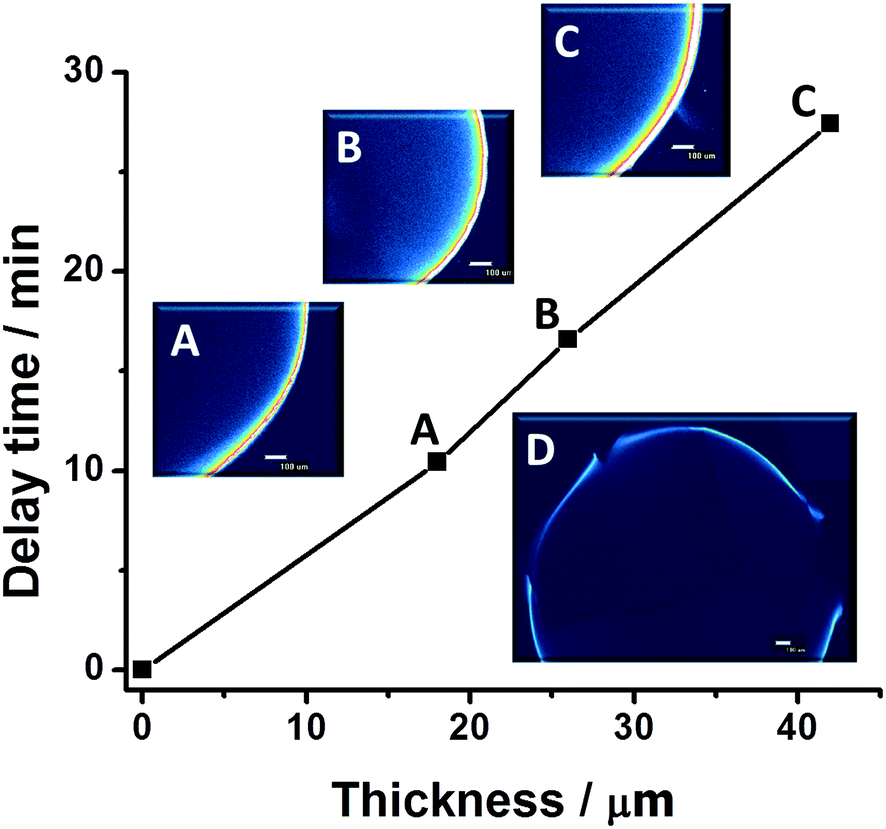 | ||
| Fig. 4 Dependence of delay time of release from the alginate core on the thickness of one (A), two (B) and three (C) layer (s) shell for 1,1 input combination with corresponding micrographs of the shell. The unlabeled point on the graph corresponds to the delay time for release from an uncoated alginate core. Inset D depicts the formation of the cracks corresponding to the beginning of release. The scale bar corresponds to 100 μm. | ||
Fig. 3 presents the kinetics of release from the bead with one PLA layer (B), two (C) and three (D) PLA layers initiated by 1,1 and 1,0 input combinations in the presence and absence of the filter.
The curves representing the release initiated by the 1,0 combination in the absence of the filter are poorly separated from the curves produced by the 1,1 combination, especially for longer periods of time (values of intensity generated by different input combinations are the same for beads with one and two layers of PLA after 120 min of monitoring). This situation is critical in the drug release system. In the case of a bead with three layers of PLA, the 1,0 and 1,1 signals are well separated even in the absence of the filter (Fig. 3D). Because this effect is not observed in the case of the uncoated beads but is enhanced with increasing the number of coating layers we believe that the coating, which impedes diffusion of citric acid inside the bead and thus slows down the release, might be a cause of it.
The presence of the filter leads to significant suppression of the output from the 1,0 combination for all layers. To determine the maximal degree of suppression, the ratio between corresponding filtered and non-filtered signals for coated beads was calculated. We found that suppression of the 1,0 signal increases with increasing numbers of layers. For one layer, after 120 min, this ratio is 1.67, for two layers it is 1.70, and is 1.93 for three layers. It is worth mentioning that the degree of suppression for coated beads is higher than that for uncoated beads (1.57). Perhaps this effect also refers to the presence of the coating, suppressing diffusion of the citric acid. In contrast, release initiated by the 1,1 signal from beads with different layers is not affected by the presence of the filter (ratio is 0.96).
Based on our previous results and the results of the current experiments the drug release mechanism can be hypothesized. Citric acid penetrates through the shell at high concentrations and binds Fe3+, thus dissolving the core. The alginate takes up a significant amount of water, resulting in strong osmotic pressure inside the core. Consequently, a considerable hydrostatic pressure is exerted onto the polymeric coating. If the latter is weakened, cracks are formed and the drug is released from these cracks. Visualization of cracks formed in a coated bead was done using a fluorescent microscope and demonstrated in Fig. 4D. This type of drug release dominates for coated beads from 1,1 and 1,0 signals and also for the 1,1 signal in the presence of the filter. Formation of cracks for these systems was observed after some delay in time. The delay in dissolution, in our case, proportionally increased with an increase in the thickness of the polymer coating. Fig. 4 illustrates the delay of release as a function of the thickness of the polymer coating for the 1,0 input combination in the absence of the filter. This mechanism of release correlates well with our previous report, where a similar pattern of release was obtained and an increase in bead diameter during dissolution of the bead coated with one layer of PLA was recorded using a fluorescent microscope.31
Importantly, the pattern of release for coated beads initiated by the 1,0 input combination in the presence of the filter is different from the other input combinations. This is probably related to the very low concentration of citric acid being produced in the filter. In this bead, pressure within the core is much lower, and so, the polymer coating can withstand the pressure, and crack formation is suppressed. In this case, drug release is primarily controlled by diffusion through an intact film coating. Indeed, for these beads, there were no cracks observed. Additionally, our results indirectly confirmed that polymer coatings play an important role in the suppression of the diffusion of citric acid inside the beads, thus suppressing drug release.
The combination of the enzymatic filter and LBL polymer coating resulted in better separation between logic-0 and logic-1 output signals, which is important for practical applications. In our case, the best performance, in terms of maximal suppression, is achieved for beads coated with three layers of PLA. It is difficult to achieve the complete suppression of release from the logic-0 signal if concentrations of the input signals are not actually zero. However, we believe that simultaneous application of the filter and polymer coating has the potential to complete this task. While the filter suppresses the logic-0 signal, the shell withstands induced pressure inside the bead, thus preventing the bead from undergoing burst release. However, for each drug separately the type of polymer, molecular weight, specific charge and porosity should be optimized to prevent the drug from leaching through the shell.
Conclusions
Through the introduction of an enzymatic filter in the enzymatic cascade, we have achieved the suppression of the 1,0 signal in the presence of the filter while maintaining the intensity of the 1,1 signal nearly unchanged. The achieved separation between logic-0 and logic-1 outputs increases the potential for this system to work as a diagnostic tool itself, which was tested and verified using ROC. Implementation of the filter for drug release has also demonstrated potential. Particularly, suppression of release from logic-0 combinations was observed for all types of beads. Furthermore, suppression of logic-0 release can be further enhanced by introducing a coating.Acknowledgements
This research was supported by the National Science Foundation award # CBET-1066397.The research was sponsored by the Laboratory Directed Research and Development Program of Oak Ridge National Laboratory, and managed by UT-Battelle, LLC, for the U. S. Department of Energy.
We would like to thank Prof. Alexei P. Sokolov (ORNL, University of Tennessee) and Prof. Vladimir Privman (Clarkson University) for fruitful discussions. Additionally, we would like to acknowledge Dr Maryna Ornatska (Elementis Specialties Inc.) for her valuable input in the preparation of the manuscript.
References
- A. Credi, Angew. Chem., Int. Ed., 2007, 46, 5472–5475 CrossRef CAS PubMed.
- A. P. De Silva, S. Uchiyama, T. P. Vance and B. Wannalerse, Coord. Chem. Rev., 2007, 251, 1623–1632 CrossRef.
- U. Pischel, Angew. Chem., Int. Ed., 2007, 46, 4026–4040 CrossRef CAS PubMed.
- K. Szacilowski, Chem. Rev., 2008, 108, 3481–3548 CrossRef CAS PubMed.
- J. Andreasson and U. Pischel, Chem. Soc. Rev., 2010, 39, 174–188 RSC.
- U. Pischel, Aust. J. Chem., 2010, 63, 148–164 CrossRef CAS.
- G. Ashkenasy and M. R. Ghadiri, J. Am. Chem. Soc., 2004, 126, 11140–11141 CrossRef CAS PubMed.
- Y. Benenson, B. Gil, U. Ben-Dor, R. Adar and E. Shapiro, Nature, 2004, 429, 423–429 CrossRef CAS PubMed.
- M. N. Stojanovic, D. Stefanovic, T. LaBean and H. Yan, Computing with nucleic acids, in Bioelectronics: From Theory to Applications, ed. I. Willner and E. Katz, 2005, pp. 427–455 Search PubMed.
- E. Shapiro and B. Gil, Nat. Nanotechnol., 2007, 2, 84–85 CrossRef CAS PubMed.
- M. N. Win and C. D. Smolke, Science, 2008, 322, 456–460 CrossRef CAS PubMed.
- Y. Benenson, Mol. Biosyst., 2009, 5, 675–685 RSC.
- J. Wang and E. Katz, Anal. Bioanal. Chem., 2010, 398, 1591–1603 CrossRef CAS PubMed.
- S. Uchiyama, N. Kawai, A. P. De Silva and K. Iwai, J. Am. Chem. Soc., 2004, 126, 3032–3033 CrossRef CAS PubMed.
- Biomolecular Computing – From Logic Systems to Smart Sensors and Actuators, ed. E. Katz, Willey-VCH, Weinheim, 2012 Search PubMed.
- R. Unger and J. Moult, Proteins, 2006, 63, 53–64 CrossRef CAS PubMed.
- Z. Ezziane, Nanotechnology, 2006, 17, R27–R39 CrossRef CAS.
- D. Margulies and A. D. Hamilton, J. Am. Chem. Soc., 2009, 131, 9142–9143 CrossRef CAS PubMed.
- K. Rinaudo, L. Bleris, R. Maddamsetti, S. Subramanian, R. Weiss and Y. Benenson, Nat. Biotechnol., 2007, 25, 795–801 CrossRef CAS PubMed.
- A. Tamsir, J. J. Tabor and C. A. Voigt, Nature, 2011, 469, 212–215 CrossRef CAS PubMed.
- Z. Li, M. A. Rosenbaum, A. Venkataraman, T. K. Tam, E. Katz and L. T. Angenent, Chem. Commun., 2011, 47, 3060–3062 RSC.
- Y. Benenson, Nat. Rev. Genet., 2012, 13, 455–468 CrossRef CAS PubMed.
- M. A. TerAvest, Z. Li and L. T. Angenent, Energy Environ. Sci., 2011, 4, 4907–4916 Search PubMed.
- Molecular and Supramolecular Information Processing – From Molecular Switches to Unconventional Computing, ed. E. Katz, Willey-VCH, Weinheim, 2012 Search PubMed.
- G. Strack, M. Pita, M. Ornatska and E. Katz, ChemBioChem, 2008, 9, 1260–1266 CrossRef CAS PubMed.
- R. Baron, O. Lioubashevski, E. Katz, T. Niazov and I. Willner, J. Phys. Chem. A, 2006, 110, 8548–8553 CrossRef CAS PubMed.
- L. Halámková, S. Mailloux, J. Halámek, A. J. L. Cooper and E. Katz, Talanta, 2012, 100, 7–11 CrossRef PubMed.
- J. Halámek, J. R. Windmiller, J. Zhou, M.-C. Chuang, P. Santhosh, G. Strack, M. A. Arugula, S. Chinnapareddy, V. Bocharova, J. Wang and E. Katz, Analyst, 2010, 135, 2249–2259 RSC.
- R. Srivastava, R. D. Jayant and M. J. McShane, J. Diabetes Sci. Technol., 2011, 5, 76–85 CrossRef PubMed.
- R. Chandrawati, P. D. Odermatt, S.-F. Chong, A. D. Price, B. Städler and F. Caruso, Nano Lett., 2011, 11, 4958–4963 CrossRef CAS PubMed.
- V. Bocharova, O. Zavalov, K. MacVittie, M. A. Arugula, N. V. Guz, M. E. Dokukin, J. Halámek, I. Sokolov, V. Privman and E. Katz, J. Mater. Chem., 2012, 22, 19709–19717 RSC.
- D. Melnikov, G. Strack, J. Zhou, J. R. Windmiller, J. Halámek, V. Bocharova, M.-C. Chuang, P. Santhosh, V. Privman, J. Wang and E. Katz, J. Phys. Chem. B, 2010, 114, 12166–12174 CrossRef CAS PubMed.
- J. Zhou, J. Halámek, V. Bocharova, J. Wang and E. Katz, Talanta, 2011, 83, 955–959 CrossRef CAS PubMed.
- S. P. Rafael, A. Vallee-Bélisle, E. Fabregas, K. Plaxco, G. Palleschi and F. Ricci, Anal. Chem., 2012, 84, 1076–1082 CrossRef CAS PubMed.
- V. Privman, J. Halámek, M. A. Arugula, D. Melnikov, V. Bocharova and E. Katz, J. Phys. Chem. B, 2010, 114, 14103–14109 CrossRef CAS PubMed.
- J. Halámek, J. Zhou, L. Halámková, V. Bocharova, V. Privman, J. Wang and E. Katz, Anal. Chem., 2011, 83, 8383–8386 CrossRef PubMed.
- J. Halámek, O. Zavalov, L. Halámková, S. Korkmaz, V. Privman and E. Katz, J. Phys. Chem. B, 2012, 116, 4457–4464 CrossRef PubMed.
- M. Pita, V. Privman, M. A. Arugula, D. Melnikov, V. Bocharova and E. Katz, Phys. Chem. Chem. Phys., 2011, 13, 4507–4513 RSC.
- K.-K. Tan, S.-L. Bang, A. Vijayan and M.-T. Chiu, Injury, 2009, 40, 978–983 CrossRef PubMed.
- G. L. Ellman, Arch. Biochem. Biophys., 1959, 82, 70–77 CrossRef CAS PubMed.
- G. Bulaj, T. Kortemme and D. P. Goldenberg, Biochemistry, 1998, 37, 8965–8972 CrossRef CAS PubMed.
- C.-J. Johansson and G. Pettersson, Eur. J. Biochem., 1974, 42, 383–388 CrossRef CAS.
- S. Harford and P. D. J. Weitzman, Biochem. J., 1975, 151, 455–458 CrossRef CAS PubMed.
- M. H. Zweig and G. Campbell, Clin. Chem., 1993, 39, 561–577 CAS.
- D. J. Hand and R. J. Till, Machine Learning, 2001, 45, 171–186 CrossRef.
- J. Fogarty, R. S. Baker and S. E. Hudson, ACM International Conference Proceeding Series, Proceedings of Graphics Interface, Waterloo, ON, 2005, pp. 129–136 Search PubMed.
- L. Halámkova, J. Halámek, V. Bocharova, S. Wolf, K. E. Mulier, G. Beilman, J. Wang and E. Katz, Analyst, 2012, 137, 1768–1770 RSC.
- D. Faraggi and B. Raiser, Stat. Med., 2002, 21, 3093–3106 CrossRef PubMed.
- P. V. Van Oostveldt, J. Demeester and J.-P. Remon, Biotechnol. Bioeng., 1993, 42, 381–386 CrossRef PubMed.
- B. Thu, P. Bruheim, T. Espevik, O. Smidsrød, P. Soon-Shiong and G. Skjåk-Bræk, Biomaterials, 1996, 17, 1031–1040 CrossRef CAS PubMed.
Footnote |
| † Electronic supplementary information (ESI) available: Experimental details on the kinetics of the enzymatic reactions are available. See DOI: 10.1039/c3bm60197h |
| This journal is © The Royal Society of Chemistry 2014 |