 Open Access Article
Creative Commons Attribution 3.0 Unported Licence
Characterization of micro- and nanocapsules for self-healing anti-corrosion coatings by high-resolution SEM with coupled transmission mode and EDX
V.-D.
Hodoroaba
*a,
D.
Akcakayiran
b,
D. O.
Grigoriev
b and
D. G.
Shchukin
c
aBAM Federal Institute for Materials Research and Testing, Division 6.8 Surface Analysis and Interfacial Chemistry, Berlin, Germany. E-mail: Dan.Hodoroaba@bam.de; Fax: +49 30 8104 1827; Tel: +49 30 8104 3144
bMax-Planck Institute of Colloids and Interfaces, Department Interfaces, 14424 Potsdam, Germany
cStephenson Institute for Renewable Energy, University of Liverpool, L69 7ZD Liverpool, UK
First published on 24th January 2014
Abstract
The observation of morphological details down to the nanometer range of the outer surface of micro-, submicro- and nanoparticles in a high-resolution scanning electron microscope (SEM) was extended with in-depth observation by enabling the transmission mode in the SEM, i.e. TSEM. The micro- and nanocapsules characterized in this study were fabricated as depots for protective agents to be embedded in innovative self-healing coatings. By combining the two imaging modes (upper and in-depth observation) complementing each other a better characterisation by a more comprehensive interpretation of the “consistency” of the challenging specimens, e.g. including details “hidden” beyond the surface or the real specimen shape at all, has been attained. Furthermore, the preparation of the quasi electron transparent samples onto thin supporting foils enables also elemental imaging by energy dispersive X-ray spectroscopy (EDX) with high spatial resolution. Valuable information on the elemental distribution in individual micro-, submicro- and even nanocapsules completes the “3D” high resolution morphological characterization at the same multimodal SEM/TSEM/EDX system.
Introduction
More and more submicro- and nanomaterials have to be “quickly”, but accurately characterized with respect to their surface morphology, shape, size and size distribution, and chemical composition as well. A field emission scanning electron microscope (FE-SEM) attached to an energy dispersive X-ray spectrometer (EDS) constitutes one established methodical approach which may be taken into consideration for such characterization.1 While a modern high-resolution SEM enables qualitative and quantitative (lateral) dimensional evaluation of specimen surface morphology at a scale down to the nanometer range, the high-resolution elemental analysis by X-ray spectroscopy is hindered by the large X-ray generation volumes in the specimen typically in the micrometer range.In many cases the inner “consistency” of particles with complex structure shall be complementary investigated, so that in-depth information by microscopy/imaging and spectroscopy/chemistry can be provided. One relevant example of specimens with such challenging analytical requirements is innovative micro- and nanocapsules filled with protective agents and incorporated in novel anti-corrosion coatings.2–4
Preparation of the electron transparent submicro- and nanocapsules on thin supporting foils as typically observed for the transmission electron microscope (TEM), i.e. on TEM grids, as well the “activation” of the transmission mode optionally available at a modern SEM, i.e. transmission in SEM (TSEM), make possible a multi-modal analytical approach consisting of high-resolution characterization of the surface morphology, in-depth inspection of the “inner” volume of the particles and elemental imaging of the thin specimens by X-ray spectroscopy with high spatial resolution. Especially for particles of sizes and complex morphology and structures as those in this study the combination of the methods above in only one instrument enables a thorough and relatively quick “3D” characterization of morphology, structure and elemental chemistry of individual particles.
Experimental and materials
Micro- and nanocapsules of various sizes, structures and chemistry have been fabricated by various approaches as part of extensive projects for development of “smart” depots for healing agents to be embedded in self-healing anti-corrosion coatings.2–4 The “smart” behaviour of the capsules containing the active substance (e.g. corrosion inhibitors and biocides) consists of the ability to regulate their permeability in response to the corrosion trigger. In practice, in the case when the new generation anti-corrosion coating is mechanically or chemically damaged, the nearby capsules are activated and release their load into the damaged area, so that the corrosion attack is terminated at an early stage, quickly and locally. In consequence, the durability of the innovative coatings is significantly prolonged, the environmental sustainability is improved, and the overall performance of the protective coating is also enhanced.2–4A large variety of capsules with sizes ranging from several tens of μm down to below 100 nm have been fabricated and systematically investigated in the present study. Representative examples were selected and are described in the Results section. In this study we present two types of capsules: polymer based polyepoxide (PE) capsules and SiO2 based inorganic capsules filled with a corrosion inhibitor. These core/shell particles were synthesized from oil in water emulsions as products of polymerisation (PE) or polycondensation (SiO2) reactions wherein the corrosion inhibitor is the oil phase. The PE capsules having 2-methylbenzothiazole as an inhibitor in their core were synthesized as described in ref. 5. The SiO2 based capsules having an organic inhibitor in their core part are synthesized according to the method proposed in ref. 6.
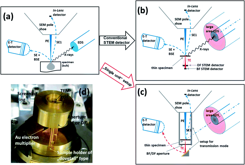
As far as the methods are concerned, as already pointed out in the Introduction, the conventional high resolution SEM has been employed mainly for resolving morphological details on the top surface of the micro- and nanocapsules. An FE-SEM of type Supra 40 from Zeiss (Oberkochen, Germany) equipped with an In-Lens detector was used, see Fig. 1a. This type of electron detector is indispensable for high-resolution imaging of the top surface of a specimen in an SEM, due to its ability to collect selectively only the high-resolution, so-called SE1 electrons emitted locally, only at the point of impact of the primary electron beam onto the specimen surface. Further instrumental details can be found in ref. 7–9.
In order to gain also valuable in-depth information on the specimen structure beyond the specimen surface, and complementing hence the surface sensitive In-Lens imaging mode, the transmission mode in SEM must be enabled. In spite of the fact that this special operation mode has demonstrated its proof-of-principle in the seventies,10 relevant applications have been reported just recently.1,11–15 In particular, the capability of metrological TSEM measurements of lateral dimensions in the nanometer range, e.g. for purposes of accurate determination of nanoparticles' size and size distribution, has been already successfully exploited. Basically, the so-called STEM detector to be placed immediately under the thin specimen can be used for acquiring images in transmission mode in a SEM, see Fig. 1b.16 In the present study a rather seldom, but commercially available transmission setup has been used, see Fig. 1c and d.17,18 This single-unit transmission setup acts as a specimen holder that enables to guide the transmitted electrons onto an electron multiplier (gold plate) and further to the conventional Everhart–Thornley detector. Further details on the operation and results of this type of producing transmission images at a SEM and comparison to the STEM detector are described elsewhere.13–15 Briefly summarizing, the quality of the images obtained by the two modes is practically equally good. It should be also noted that even if working with high-end, high-resolution SEMs in the transmission mode, the spatial resolution which is typical for TEMs cannot be practically attained. The much higher accelerating voltages as well as the aberration correctors available in a TEM make the spatial resolution attainable in a TEM significantly superior to that of any T-SEM system.
Furthermore, by preparing the quasi electron transparent specimens onto thin TEM supporting foils the excitation volume responsible for the generation of X-rays is significantly reduced, so that the acquired EDX spectra with a conventional EDX detector at a SEM operating in the transmission mode address a high spatial resolution. Of course, especially for nanoobjects, the EDX signals will be very weak. However, the employment of the newly developed large-area SDD (silicon drift detector) EDS can improve significantly the signal-to-noise ratio and ensures valuable elemental information over the X-ray spectra also for nanoobjects. In this study two EDX spectrometers were employed, an SDD one of type XFlash® 5010 from Bruker (Berlin, Germany) and a Si(Li) one from Thermo Fisher Scientific (Waltham, MA, USA) both with a detector active area of 10 mm2.7–9,19
The micro- and nanocapsules have been prepared from the suspension or powder form after corresponding dilution (in distilled water or in isopropanol) with, in some cases, 2 min treatment in an ultrasonic bath, pipetting 1 μl onto various TEM grids (the lacey carbon films giving the best results) and finally drying. To what extent the specific sample preparation procedure affects the morphology and structure of the specimens investigated could not be established in the present study and remains a challenging task for further investigation. Changes at least in the silica particle size during the analysis in the electron microscope (under electron bombardment and vacuum) cannot be excluded.20
The remarkable powerful analytical characterization of the challenging specimens of complex morphology and structure chosen in this study can be demonstrated in a convincing way by employing the multi-method approach conceived above, namely the high-resolution imaging of the top surface morphology combined with in-depth transmission imaging and X-ray imaging for elemental distribution with high spatial resolution – all in one instrument. To our knowledge there are no other reports published until now about exploiting such a methodical approach. Furthermore, due to the on-going significant increase of instrumental performance of SEM/EDX systems, such as imaging resolution of SEMs or EDS detectors with a very large collecting solid angle, the authors expect a broad application of high-resolution SEM/TSEM/EDX especially for quick (in comparison to TEM) and accurate characterization of submicro- and nanoparticles.
Results and interpretation
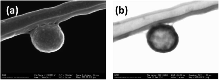
Having described above the materials to be characterized as well as the methods and the instrumentation to be applied, representative examples of characterizing analysis were selected and are discussed in the following.Fig. 2 shows in “double pack” the two complementary imaging modes, upper observation with the In-Lens detector and the corresponding TSEM image of the same lateral scanned outer size. The particle is stuck to a string of the lacey carbon supporting foil onto the TEM grid and has practically no substrate beyond it, i.e. offering hence excellent analysis conditions due to the absence of mostly disturbing interactions with the substrate. While the In-Lens imaging mode supplies the expected high-resolution morphology of the outer surface of the particle, the transmission imaging mode reveals the shell-like structure of the capsule. Neither a conventional SEM alone nor a TEM alone is able to characterize both the nanomorphology of the outer specimen surface and the inner structure of the submicrometer particle. However, a clear statement on the composition of the capsule, whether the core is filled by the inhibitor (as expected by manufacturer) or the capsule is empty, cannot be given. Due to the closeness of the particle to the carbon support strand at which the particle sticks at, an EDX analysis cannot identify reliably the possible presence of carbon in the core of the particle.
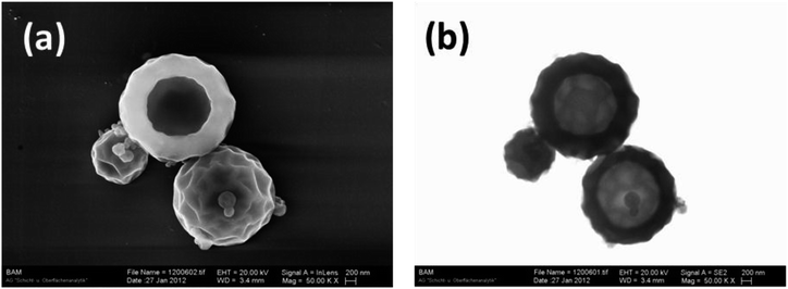
A somewhat similar tricky arrangement of several submicroparticles sizing from the micrometer down to the nanometer range is shown – again in a double pack as upper and in-depth observations – in Fig. 3. The imaging mode with the In-Lens is able to detect sensitively morphological details on the surface of the bigger particles and also detect small nanoparticles adhered onto the surface of the bigger particles. In turn, the TSEM image reveals such in-depth complementary information that demonstrates the same calotte shape of the two big particles in Fig. 3 spatially oriented in opposite directions. If in the TSEM mode the two particles look very similar, in the In-Lens surface sensitive mode one can observe the inner surface of one particle as well as the outer surface of the other (big) particle. Here again the use of either only a SEM or only TEM could have led to the misinterpretation of the real particle shape.
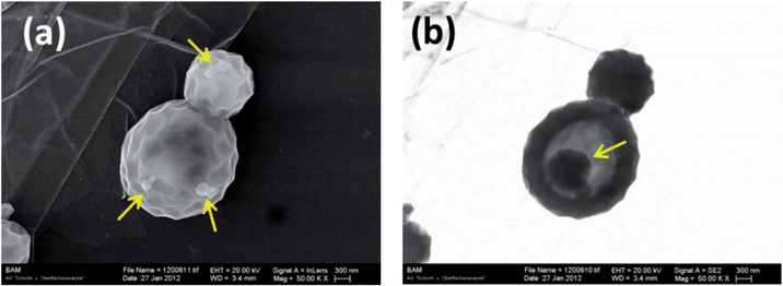
The example in Fig. 4 reveals the real shape of another particle package if both imaging modes are taken into account. Only the conventional SEM imaging (Fig. 4a) suggests massive, nearly spherical particles with fine details on their surface. However, the real shape of the particles becomes evident when the complementary image in transmission mode is evaluated: the bottom particle is not massive, but rather shell-like, i.e. half-capsules – as reported also elsewhere21 and “hides” also another particle beyond its surface.
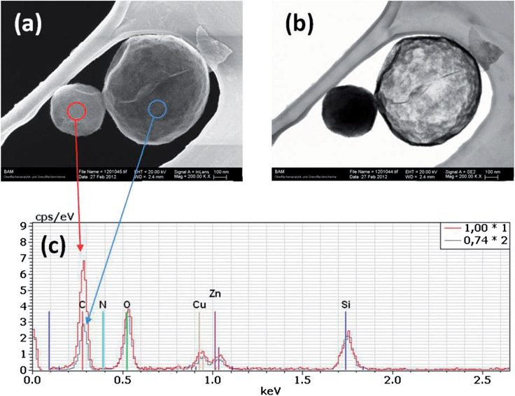
The result of imaging two neighbour silica particles of completely different structures (consistency) using the dual mode In-Lens/TSEM is presented in Fig. 5a and b, respectively. If the two particles look quite similar in the “upper” (In-Lens) observation mode (Fig. 5a), the difference between them becomes evident in the transmission imaging mode (Fig. 5b). The TSEM image suggests that the smaller particle is either constituted by a material heavier than the big particle or a thick (electron non-transparent) shell or filled with a substance – opposite to the big particle which seems to be “empty”, constituted only by a thin shell. Activating EDX onto the defined areas equally large on the two particles, it is quickly confirmed that the smaller particle is filled with a carbon rich substance and the big particle is mainly constituted by a SiO2 thin shell.
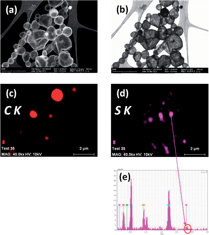
A last example continuing the characterisation treatment applied to the same type of particle as those illustrated in Fig. 5 but at smaller magnifications, and thus considering a large number of particles, is shown in Fig. 6. Similar features can be recognized in Fig. 6a and b. EDX qualitative elemental maps of selected elements of interest are shown in Fig. 6c (carbon) and 6d (sulphur). If the distribution of carbon is quite clear and can be explained by the presence of carbon in smaller particles as evidence for the successful filling of the capsules with the corrosion inhibitor, the presence of sulphur was not expected as no sulphur contained components were used in the manufacturing process. Therefore, an EDX spectrum has been extracted from a sulphur-“rich” area marked in Fig. 6d. The EDX spectrum shows a weak signal of the S K line, which is, however, at the limit of detection, so that the presence of sulphur cannot be undoubtedly confirmed. This example was specially selected with the purpose to show deliberately also the limits of the methodical approach applied in the present study. Due to the very small amount of substance excited by the electrons which in turn produce X-ray spectra of poor signal-to-noise ratios, the limits of detection of the EDX are rather poor. Nevertheless, the value of the elemental (distribution) information in such small particles is impressive. There is only reason to come towards the very recent markedly technological developments in the field of large area SDD EDS detectors. Especially the significantly larger collection solid angle as well as the quick processing electronics result in considerably higher signal-to-noise ratios in the EDX X-ray spectra, so that the high spatial resolution EDX can excellently complete the high-resolution SEM imaging both laterally and in transmission mode in a single instrument as a very powerful analytical tool for quick and accurate characterization of smaller and smaller particles.
One basic question that could not be fully answered in the present study is to what extent the morphology, shape, structure and chemical composition of the investigated capsules are influenced by the sample preparation, high-vacuum or the electron bombardment. The fact that the most larger capsules in Fig. 6 are both somewhat squashed and missing the expected oil filling can be attributed to a faulty synthesis, but one of the artefacts above cannot be excluded. To our knowledge the literature helping one to elucidate this challenging issue is rather scarce.20,22
Conclusions
A multimodal methodical approach has been successfully applied for the advanced characterization of micro-, submicro- and nanocapsules filled with protective agents and incorporated them into new self-healing coatings. It is demonstrated by examples on how the complexity of both the morphology and composition of the challenging specimens emphasizes the analytical strengths of each particular method. By a combination of them, a thorough characterizing picture by means of only one measurement system finally results: high-resolution SEM imaging of the top surface of the specimens, in-depth observation of individual particles by the transmission mode in SEM (TSEM), and elemental imaging by EDX with high spatial resolution. The prerequisite for this detailed characterization is the preparation of the quasi electron transparent particles on thin foils as typically observed for TEM and the possibility to take images in transmission mode with a special transmission setup. Hence, the real shape of the capsules could be interpreted better and hidden details beyond the outer surface of the specimens could be visualised. Nevertheless, care must be taken with respect to possible influences of the sample preparation, vacuum and electron bombardment on the real shape, structure and even chemical composition of the particles under investigation relative to their state immediately after the particle synthesis.Acknowledgements
The authors would like to thank Mrs Sigrid Benemann (BAM-6.8) for taking careful measurements. D. Grigoriev and D. Akcakayiran acknowledge financial support from the European G8 project “Multiscale smart coatings with sustained anticorrosive action – smart coat”.Notes and references
- V.-D. Hodoroaba, S. Rades, N. Kishore, G. Orts-Gil and W. E. S. Unger, Imaging & Microscopy, 2013, 15, 54 Search PubMed.
- D. G. Shchukin, D. O. Grigoriev and H. Möhwald, Soft Matter, 2010, 6, 720 RSC.
- A. Latnikova, D. O. Grigoriev, H. Möhwald and D. G. Shchukin, J. Phys. Chem. C, 2012, 116, 8181 CAS.
- D. G. Shchukin and H. Möhwald, Small, 2007, 3, 926 CrossRef CAS PubMed.
- D. O. Grigoriev, M. F. Haase, N. Fandrich, A. Latnikova and D. G. Shchukin, Bioinspired, Biomimetic Nanobiomater., 2012, 1, 101 CrossRef CAS.
- N. Lapidot, O. Gans, F. Biagini, L. Sosonkin and C. Rottman, J. Sol-Gel Sci. Technol., 2003, 26, 67 CrossRef CAS.
- M. Procop and V.-D. Hodoroaba, Microchim. Acta, 2008, 161, 413 CrossRef CAS.
- V.-D. Hodoroaba, M. Radtke, L. Vincze, V. Rackwitz and D. Reuter, Nucl. Instrum. Methods Phys. Res., Sect. B, 2010, 268, 3568 CrossRef CAS PubMed.
- V.-D. Hodoroaba and M. Procop, X-Ray Spectrom., 2009, 38, 216 CrossRef CAS.
- L. Reimer, B. Volbert and P. Bracker, Scanning, 1979, 2, 96 CrossRef CAS.
- E. Buhr, N. Senftleben, T. Klein, D. Bergmann, D. Gnieser, C. G. Frase and H. Bosse, Meas. Sci. Technol., 2009, 20, 084025 CrossRef.
- T. Klein, E. Buhr, K.-P. Johnsen and C. G. Frase, Meas. Sci. Technol., 2011, 22, 094002 CrossRef.
- V.-D. Hodoroaba, S. Benemann, C. Motzkus, T. Macé, P. Palmas and S. Vaslin-Reimann, Microsc. Microanal., 2012, 18(2), 1750 CrossRef.
- V.-D. Hodoroaba, C. Motzkus, T. Macé and S. Vaslin-Reimann, Microsc. Microanal., 2014 DOI:10.1017/S1431927614000014.
- C. Motzkus, T. Macé, F. Gaie-Levrel, S. Ducourtieux, A. Delvallee, K. Dirscherl, V.-D. Hodoroaba, I. Popov, O. Popov, I. Kuselman, K. Takahat, K. Ehara, P. Ausset, M. Maillé, N. Michielsen, S. Bondiguel, F. Gensdarmes, L. Morawska, G. Johnson, E. M. Faghihi, C. S. Kim, Y. H. Kim, M. C. Chu, J. A. Guardado, A. Salas, G. Capannelli, C. Costa, T. Bostrom, Å. K. Jämting, M. A. Lawn, L. Adlem and S. Vaslin-Reimann, J. Nano Res., 2013, 15, 1919, DOI:10.1007/s11051-013-1919-4.
- J. P. Vermeulen and H. Jaksch, Imaging & Microscopy, 2005, 1, 22 Search PubMed.
- U. Golla, B. Schindler and L. Reimer, J. Microsc., 1994, 173, 219 CrossRef CAS.
- U. Golla-Schindler and B. Schindler, US Pat. 6,815,678 B2, 2004.
- V.-D. Hodoroaba, K. J. Kim and W. E. S. Unger, Surf. Interface Anal., 2012, 44, 1459 CrossRef CAS.
- K. Y. Jung, B. C. Park, W. Y. Song, B.-H. O and T. B. Eom, Powder Technol., 2002, 126, 255 CrossRef CAS.
- V.-D. Hodoroaba, S. Rades and W. E. S. Unger, Surf. Interface Anal., 2014, 46 DOI:10.1002/sia.5426.
- F. Tiarks, K. Landfester and M. Antonietti, Langmuir, 2001, 17, 908 CrossRef CAS.
| This journal is © The Royal Society of Chemistry 2014 |

