Microfluidic serial dilution ladder†
Siavash
Ahrar
,
Michelle
Hwang
,
Philip N.
Duncan
and
Elliot E.
Hui
*
Department of Biomedical Engineering, University of California, Irvine, 3120 Natural Sciences II, Irvine, CA 92697-2715, USA. E-mail: eehui@uci.edu; Tel: +1 (949) 824-8723
First published on 6th November 2013
Abstract
Serial dilution is a fundamental procedure that is common to a large number of laboratory protocols. Automation of serial dilution is thus a valuable component for lab-on-a-chip systems. While a handful of different microfluidic strategies for serial dilution have been reported, approaches based on continuous flow mixing inherently consume larger amounts of sample volume and chip real estate. We employ valve-driven circulatory mixing to address these issues and also introduce a novel device structure to store each stage of the dilution process. The dilution strategy is based on sequentially mixing the rungs of a ladder structure. We demonstrate a 7-stage series of 1![[thin space (1/6-em)]](https://www.rsc.org/images/entities/char_2009.gif) :1 dilutions with R2 equal to 0.995 in an active device area of 1 cm2.
:1 dilutions with R2 equal to 0.995 in an active device area of 1 cm2.
1. Introduction
Serial dilution is a fundamental laboratory procedure for creating a logarithmic range of solute concentrations and is commonly used to create calibration standards, a range of test solutions, or highly diluted samples. The procedure involves a series of pipetting operations that must be performed with good accuracy. While this is straightforward for an experienced technician, it is beyond the capability of untrained users and thus automated serial dilution may be useful in point-of-care settings.A number of microfluidic devices for serial dilution have been previously reported. Continuous flow approaches utilize a tiered network of resistors to mix two fluids at ratios specified by the circuit design.1,2 These devices output an entire dilution series in parallel and are composed of simple channel networks with no moving parts. However, the need to sustain continuous flow requires a relatively large initial sample volume (5–100 μL),1 and long channel lengths are required to enable good mixing, resulting in fairly large devices (∼12 cm2).1 Additionally, the total fluidic resistance of this approach increases nonlinearly as the number of dilution steps increases, hence the scaling potential is unclear.
A second approach utilizes integrated valves to meter and mix defined volumes of sample and buffer. Paegel and colleagues implemented such an approach based on peristaltic pumping around a single ring mixer.3 A small sample (400 nL) was diluted by a fixed ratio during each dilution step, in which a volume of buffer was metered into the ring and circulated until fully mixed with the sample. The recirculating design eliminated the need for banks of long mixing channels, thus resulting in a compact device (∼1 cm2). Additionally, the possible number of sequential dilution steps was essentially unlimited. However, only the final dilution was stored, and the intermediate steps in the dilution series were discarded.
Here, we present an evolution of the Paegel dilution ring that is capable of storing every stage of dilution. As illustrated in Fig. 1, a series of chambers are arranged like rungs on a ladder and primed with a buffer solution. A small sample volume of 240 nL is loaded into the top rung. To begin the dilution process, the top two rungs are connected to form a loop, and the liquid contents are mixed by peristaltic pumping to perform a 1:1 dilution. The second and third rungs are then connected and mixed to perform a subsequent dilution, and the process is repeated all the way down the ladder. When completed, the full dilution series is stored on the rungs of the ladder. The design is readily scalable, as dilution stages can be added with additional rungs. We demonstrate a 7-stage dilution in an active device area of only 1 cm2.
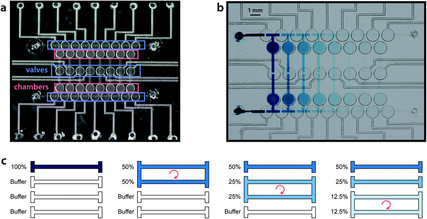 | ||
| Fig. 1 Microfluidic serial dilution ladder. (a) Fabricated device structure. Pneumatic valves control the connections between each rung of the ladder as well as peristaltic pumping. Passive membrane deflection within the liquid chambers allows for changes in liquid volume to be accommodated as the valves open and close. (b) Serial dilution is visualized with the use of a color dye. (c) Serial dilution strategy. The ladder is primed with buffer, and the sample is loaded into the first rung. Pairs of rungs are mixed sequentially to generate a 1:1 dilution series. | ||
2. Methods
Microdevice manufacture
The dilution ladder device utilized a normally closed elastomeric membrane valve technology as previously reported.4 Briefly, valve chambers and channels were patterned in a glass wafer (Telic Co., Valencia, CA, USA) by photolithography and HF wet etching. The wafer was diced and ports for fluid and pneumatic access were drilled through the glass with diamond-tipped grinding bits (McMaster-Carr). Two patterned glass layers were then sandwiched around a 250 μm thick silicone membrane (HT-6240, Rogers Corp.) and held together reversibly by adhesion. Via ports in the membrane were formed with a biopsy punch prior to assembly. Valve actuation was accomplished by deflecting this layer pneumatically. For handling reagents that are not compatible with silicone, Teflon5 or polyurethane6 membranes may be used instead.Pneumatic control
Valves from the dilution ladder were individually addressed with a vacuum-driven solenoid valve array (http://www.stanford.edu/group/foundry) under the control of LabView software (National Instruments). Circulating flow in each loop was driven by peristaltic pumping via four pneumatic valves, as illustrated in Fig. 2.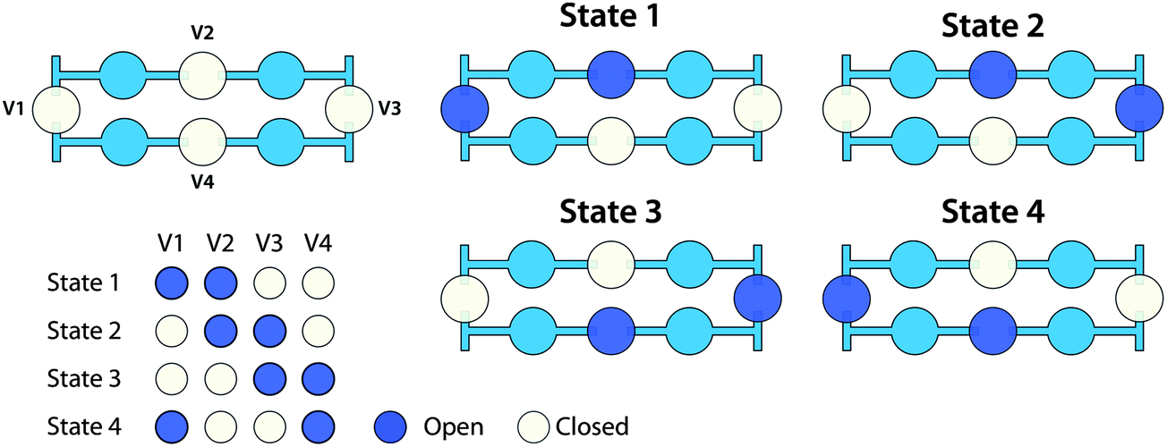 | ||
| Fig. 2 Peristaltic pumping is used to circulate liquid around two rungs of the dilution ladder for mixing. The four pneumatic valves are actuated at a rate of 3 Hz: the valves cycle sequentially through the four states three times every second. | ||
Fluid-expansion chambers
As the rungs of the dilution ladder switch between the resting and pumping states, liquid volume is not conserved. At rest, all four valves in a loop are closed, but during pumping, two valves are open at all times (Fig. 2). In order to accommodate this change in volume, two chambers were added to each rung (Fig. 1a). Each chamber is similar in structure to a valve, but has no pneumatic connection. In each chamber, a flexible silicone membrane separates a volume of liquid and a volume of air. As the liquid volume increases or decreases, the membrane can deflect to accommodate the change.Fluorescence quantification
400 μM fluorescein sodium salt (Sigma Aldrich) was diluted into TE buffer with 0.2% Triton-X at pH 8.3. Fluorescein concentrations were visualized with a 4× objective on a Nikon Eclipse TE200 microscope with a QIClick CCD camera (QImaging). Image quantification was performed with ImageJ software (NIH). For each rung of the dilution ladder, the average and standard deviation of fluorescence intensity were calculated from measurements of six regions distributed across the rung. Dilutions were plotted as the base-2 logarithm of fluorescence intensity for each stage, and the accuracy of dilution was quantified by linear regression.3. Results and discussion
The device was initially primed by filling each rung of the ladder sequentially. Buffer was injected into each rung while the remainder of the channel network was valved off. A sample was then injected into the first rung of the device (240 nL per rung), and serial dilution was performed by sequential circulation down the ladder, as illustrated in Fig. 1c. The first rung was mixed with the second rung to perform a 50% dilution. The second rung was then mixed with the third rung to create a 25% dilution of the original sample, and the process was continued down the eight rungs of the ladder (7 loops). Circulation around each loop was performed by peristaltic pumping as illustrated in Fig. 2, at a frequency of 3 Hz (3 cycles per second, with 4 valve states per cycle). At each stage of dilution, the liquids were circulated for a duration of 3 minutes to ensure sufficient mixing.3Food dye was first diluted into water to facilitate visualization of device operation (Fig. 1b, ESI, Movie 1†). Next, in order to quantify dilution efficiency, fluorescein was diluted into TE buffer and imaged by fluorescence microscopy. The log2 plot of fluorescence intensity for each dilution stage showed excellent linearity (R2 = 0.995 to 0.997 over 3 trials), demonstrating that the device can perform a 7-stage 1:1 serial dilution with very high accuracy (Fig. 3).
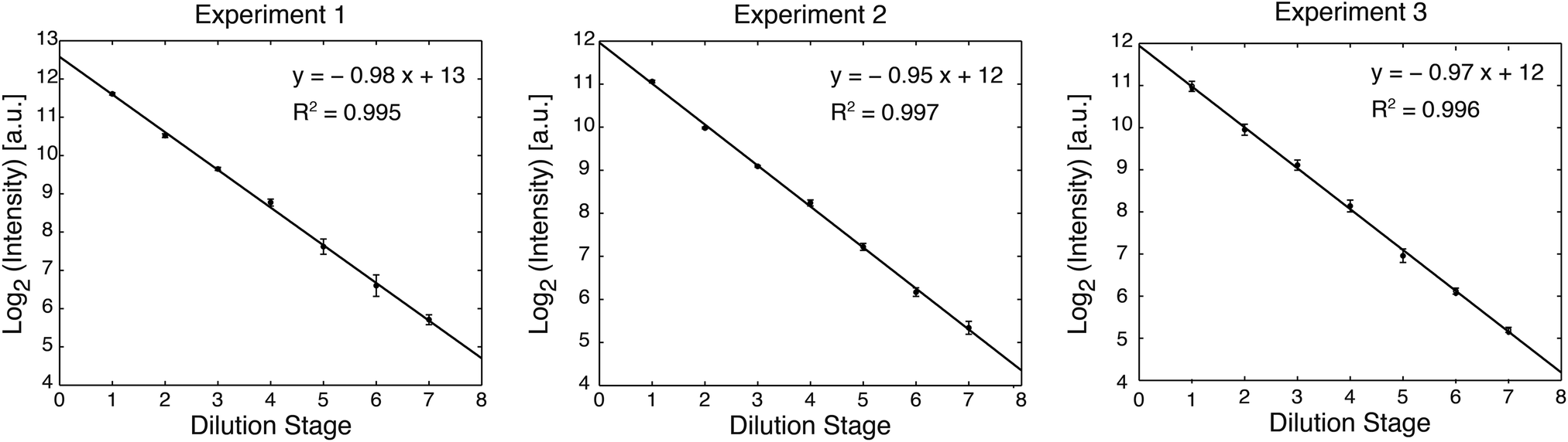 | ||
| Fig. 3 Quantitative evaluation of serial dilution efficiency. Fluorescein was serially diluted into TE buffer and measured by fluorescence microscopy. The log2 plot of fluorescence intensity demonstrates good linearity over three independent experiments. | ||
Extending the design to perform more dilution stages should be straightforward, requiring only the addition of more rungs to the ladder. The 7-stage device is fairly compact, with the ladder structure measuring 8 mm wide by 13 mm long. In comparison, a previously reported continuous flow design required a 6 cm long device to achieve 8 dilution stages.1
Our device builds off of the circulatory mixing of the Paegel device,3 but adds the ability to store each stage of dilution. This can also be accomplished by a different strategy, which utilizes valves to direct packets of liquid around a 8 × 8 grid structure.7 This versatile device is capable of a variety of complex liquid manipulations, and by mixing and splitting different volumes of liquid, the device can perform multistage serial dilutions with storage of each dilution stage. Rather than pursuing this level of flexibility and modularity, we designed a simple device focused solely on serial dilution. The strategy is straightforward and should be readily incorporated into larger microfluidic systems.
Alternative strategies for serial dilution have also been demonstrated by using droplet microfluidics.8,9 As with our method, these approaches are capable of processing small samples and can store each stage of dilution in a separate droplet. While droplet devices have the advantage of simplicity, with no moving parts, valve-based systems offer more flexibility. If serial dilution is not the end goal but rather the beginning of a multi-step procedure, the required liquid-handling manipulations may be complex enough that valves become required even in a droplet device. Furthermore, droplet systems require off-chip pumps that add to the complexity of the total system. In our design, the pumps are integrated into the device itself. While in the current implementation these on-chip pumps require off-chip actuation, we have shown elsewhere that pump control can be accomplished by on-chip microfluidic circuits.10,11 The emergence of microfluidic digital logic technologies12 offers the possibility that complex control algorithms can be programmed directly into microfluidic circuits, allowing devices to operate autonomously without the need for external controllers. The serial dilution method presented here may be well suited for integration into such systems, thus allowing complex sample processing to be combined with very simple user operation.
Acknowledgements
This work was supported by the NSF (ECCS-1102397) and the DARPA N/MEMS S&T Fundamentals Program under N66001-1-4003 issued by SPAWAR to the Micro/Nano Fluidics Fundamentals Focus (MF3) Center. S.A. was supported by a fellowship via the NSF LifeChips IGERT (#0549479).References
- X. Y. Jiang, J. M. K. Ng, A. D. Stroock, S. K. W. Dertinger and G. M. Whitesides, J. Am. Chem. Soc., 2003, 125, 5294–5295 CrossRef CAS PubMed.
- C. Kim, K. Lee, J. H. Kim, K. S. Shin, K. J. Lee, T. S. Kim and J. Y. Kang, Lab Chip, 2008, 8, 473–479 RSC.
- B. M. Paegel, W. H. Grover, A. M. Skelley, R. A. Mathies and G. F. Joyce, Anal. Chem., 2006, 78, 7522–7527 CrossRef CAS PubMed.
- W. H. Grover, A. M. Skelley, C. N. Liu, E. T. Lagally and R. A. Mathies, Sens. Actuators, B, 2003, 89, 315–323 CrossRef CAS.
- W. H. Grover, M. G. von Muhlen and S. R. Manalis, Lab Chip, 2008, 8, 913–918 RSC.
- W. Inman, K. Domansky, J. Serdy, B. Owens, D. Trumper and L. G. Griffith, J. Micromech. Microeng., 2007, 17, 891–899 CrossRef.
- E. C. Jensen, A. M. Stockton, T. N. Chiesl, J. Kim, A. Bera and R. A. Mathies, Lab Chip, 2013, 13, 288–296 RSC.
- X. Niu, F. Gielen, J. B. Edel and A. J. deMello, Nat. Chem., 2011, 3, 437–442 CrossRef CAS PubMed.
- P. M. Korczyk, L. Derzsi, S. Jakiela and P. Garstecki, Lab Chip, 2013, 13, 4096–4102 RSC.
- P. N. Duncan, T. V. Nguyen and E. E. Hui, Proc. Natl. Acad. Sci. U. S. A., 2013, 110, 18104–18109 CrossRef PubMed.
- T. V. Nguyen, P. N. Duncan, S. Ahrar and E. E. Hui, Lab Chip, 2012, 12, 3991–3994 RSC.
- B. Mosadegh, T. Bersano-Begey, J. Y. Park, M. A. Burns and S. Takayama, Lab Chip, 2011, 11, 2813–2818 RSC.
Footnote |
| † Electronic supplementary information (ESI) available: Operation of serial dilution ladder. For illustrative purposes, video playback is 4× real time, and only the first 4 seconds of mixing (16 s in real time) are shown for each stage. See DOI: 10.1039/c3an01710a |
| This journal is © The Royal Society of Chemistry 2014 |