Tunable negative permittivity behavior and conductor–insulator transition in dual composites prepared by selective reduction reaction
Zi-dong
Zhang
ab,
Run-hua
Fan
*a,
Zhi-cheng
Shi
a,
Shi-bing
Pan
a,
Ke-lan
Yan
a,
Kang-ning
Sun
a,
Jing-de
Zhang
a,
Xiang-fa
Liu
a,
Xiao Lin
Wang
*b and
Shi Xue
Dou
b
aKey Laboratory for Liquid-Solid Structural Evolution and Processing of Materials (Ministry of Education), Shandong University, Jinan 250061, China. E-mail: fan@sdu.edu.cn; Tel: +86-531-883-93396
bInstitute for Superconducting and Electronic Materials, University of Wollongong, Wollongong, New South Wales 2500, Australia. E-mail: xiaolin@uow.edu.au; Tel: +61-2-4421-5766
First published on 2nd November 2012
Abstract
We use a selective reduction reaction to fabricate a new kind of dual composite, which has a “composite-within-a-composite” structure. Based on the different reduction behavior of Fe2O3, an Fe-rich structure (Fe–Fe3O4–Al2O3) is formed in an Al-rich structure (FeAl2O4–Al2O3). The Fe-rich structure can bring down the concentration of free electrons to reduce the energy loss, without losing its metallic behaviour at the same time. Near the percolation threshold, a conductor–insulator transition appears and the dual composites show totally different electromagnetic responses, which can be well explained by effective medium theory. By controlling the parameters of the selective reduction process, we can get a tunable negative permittivity, which implies the ability to continuously change their electromagnetic properties.
Introduction
Almost all electromagnetic phenomena can be explained by the interactions between waves and materials. As we know, the response of a material to electromagnetic waves is largely determined by only two parameters: permittivity (ε) and permeability (μ). Conventional materials have both positive ε and positive μ. In 1968, Veselago made a theoretical study of materials in which both the permittivity and the permeability are simultaneously negative.1 Materials of this type are called double negative materials (DNMs), also left-handed materials (LHMs). The number of DNMs has rapidly grown and blossomed since J. Pendry's famous prediction of perfect lens beyond the diffraction limit in 2000.2In 2000, Smith et al. achieved negative permeability and permittivity at microwave frequencies via an artificial structure, named “metamaterial”.3 The phenomenon of negative refraction was also discovered by using this medium in 2001,4 which led to an explosion of interest in this field. Since Smith's work, negative refraction has been found in different frequency ranges, from radio frequency (21 MHz) to visible light by using metamaterials.5–9 Although the term “metamaterials” has been widely used since the beginning of this century, the exact meaning of “metamaterial” is still nebulous. A metamaterial has been defined as an artificial structure which attains its properties from its unit structure rather than from its constituent materials.10 According to the definition, the fascinating electromagnetic responses of metamaterials originate from their structural units rather than the materials' natural properties.
At the same time, it is also an interesting and challenging objective to search for “real” materials which can be used as DNMs due to their constituent materials' natural properties. There are some theoretical suggestions and experimental results on this topic. N. Limberopoulos et al.11 prepared MgB2–SiC composites, which showed both negative permittivity and negative permeability at optical frequencies. J. Zhou et al.12 reported the potential application of graphite to obtain negative refraction. Ceramic matrix composites, composed of metallic ferromagnetic nanoparticles, have been theoretically proposed as DNM candidates by S. T. Chui and L. Hu.13 According to Chui's research, the metal particles can contribute excellent electromagnetic properties to the composite. In contrast to periodic structures, ceramic matrix composites obtain their negative permittivity from their conducting phases and their negative permeability from the ferromagnetic resonance of magnetic phases.14
If we want to use metal–ceramic composites as DNMs, it is very important to reduce the energy loss that is caused by free electrons in the metal component. For this purpose, we have used a selective reduction reaction to fabricate a new kind of dual composite in one step (Fig. 1). The dual composite can be described as a composite-within-a-composite. In our study, based on the different reduction equations of Fe2O3,15,16 we have used an Fe-rich structure (Fe–Fe3O4–Al2O3) to replace the pure metal. The Fe-rich structure can bring down the concentration of free electrons to reduce the energy loss, without losing its metallic behaviour at the same time. By controlling the parameters of the selective reduction process, such as reduction temperature and time, we can adjust the content of the conductive phase and the size of the conductive particles, and thus get controllable dielectric properties to obtain negative permittivity in the GHz range. For example, if we decrease the reduction temperature, the grain of the conductive particles could be refined, leading to lower dielectric loss.
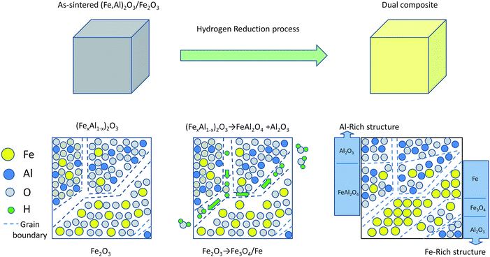 | ||
| Fig. 1 Schematic diagram showing the fabrication of the dual composites. | ||
At the same time, a ferromagnetic resonance or Mie resonance can be used to provide negative permeability in GHz frequency range.17 Ferromagnetic resonance has been widely studied during the last century, and it can be excited easily by applying an external DC magnetic field to achieve negative permeability in the GHz range.18–20
The negative permittivity behaviour of dual composites,21,22 however, has not been well studied, because the boundary conditions in dual composites are so complicated. In such a case, the effective medium theory (EMT) is the most suitable approach to this question.10 The mechanism responsible for the dual composites' permittivity behaviour will be discussed based on the EMT in the following section.
Experimental
Precursor preparation
The Fe2O3–Al2O3 mixtures, with different Fe2O3 molar ratios from 10% to 60%, are designated as FA10, FA20, FA40, FA50, and FA60, respectively. 1 wt% MgO is also added to promote good sintering performance.The mixtures are wet milled in ethanol for 10 hours and dried at 373 K for 3 hours. Then, the powders are pressed under 40 kN for 2 min to prepare plates (15 mm2 with thickness of 4 mm), followed by pressureless sintering in air at 1573 K for 1.5 hours.
Dual composite preparation
The as-sintered products are placed in a tube furnace and isothermally reduced in hydrogen for 3 hours at 873 K to yield the dual composites.Composite analysis
The phase identification of samples was performed by X-ray diffraction using Cu Kα radiation. In order to obtain the accurate phase composition, Mössbauer (MS) spectra were collected at room temperature, using a 57Co source contained in a Rh matrix, with operation in conventional constant-acceleration mode.The dielectric properties of the composites were also measured by using an impedance analyser (Agilent, 4991A). In order to get a better understanding of the relationship between microstructure and dielectric properties, the effective medium theory is used to calculate the dielectric parameters of each sample.
Phase characterization
Fig. 2 shows the X-ray diffraction (XRD) patterns of the samples. As shown in Fig. 2, there are peaks associated with α-Al2O3 and Fe, and no peaks of Fe2O3 can be detected, revealing that the Fe2O3 has been completely reduced. The (1 0 4) peak of α-Al2O3 shows a notable shift in the peak position towards the lower angle (2θ) side after reduction. Since the ionic radius of Fe3+ (0.065 nm) is larger than that of Al3+ (0.054 nm), dissolution of Fe3+ by substitution for Al3+ in the cationic sub-lattice of Al2O3 leads to the expansion of the lattice, as observed.23 Peaks corresponding to the Fe3O4 are also detected when the Fe2O3 molar ratio exceeds 10 mol%. FeAl2O4 spinel phase, which is known to form during the reducing reaction of the Fe2O3–Al2O3 system in H2 at temperatures lower than 1000 °C,24 is not detected in all samples. We could not rule out its presence, however, because the spinel phase peaks may be masked by α-Fe peaks or those of the (FexAl1−x)2O3 solid solution.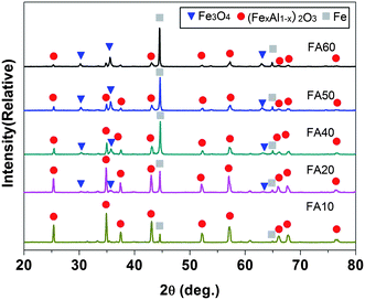 | ||
| Fig. 2 XRD patterns (Cu Kα, λ = 0.154 nm) of the samples, which have varying mol% of Fe2O3, as indicated by the sample designations. | ||
In order to obtain the accurate phase composition, Mössbauer (MS) spectra were collected at room temperature. By detecting the response of the Fe nucleus to its environment, we can get three types of nuclear interaction. The Mössbauer spectroscopy parameters of all samples are listed in Table 1, while Fig. 3 shows only the Mössbauer spectroscopy (MS) patterns of samples FA20 and FA40.
| Subspectrum | IS/mm s−1 | QS/mm s−1 | Magnetic field/T | A/% | |
|---|---|---|---|---|---|
| FA10 | Fe sextet | 0.00 | 0.00 | 33.11 | 21.2 |
| Fe3+ doublet(1) | 0.30 | 0.53 | — | 65.8 | |
| Fe2+ doublet(2) | 0.80 | 1.67 | — | 13.0 | |
| FA20 | Fe sextet | 0.00 | 0.00 | 33.14 | 40.5 |
| Fe3O4 sextet | 0.45 | 0.14 | 44.28 | 13.7 | |
| Fe3+ doublet(1) | 0.30 | 0.53 | — | 35.2 | |
| Fe2+ doublet(2) | 0.83 | 1.83 | — | 10.5 | |
| FA40 | Fe sextet | 0.00 | 0.00 | 33.16 | 51.6 |
| Fe3O4 sextet | 0.34 | 0.02 | 46.52 | 13.8 | |
| Fe3O4 sextet | 0.60 | −0.12 | 42.37 | 14.1 | |
| Fe3+ doublet(1) | 0.32 | 0.59 | — | 14.9 | |
| Fe2+ doublet(2) | 0.94 | 1.90 | — | 5.7 | |
| FA50 | Fe sextet | 0.00 | 0.00 | 33.17 | 47.3 |
| Fe3O4 sextet | 0.33 | 0.07 | 46.63 | 18.8 | |
| Fe3O4 sextet | 0.60 | −0.06 | 42.80 | 17.7 | |
| Fe3+ doublet(1) | 0.34 | 0.55 | — | 9.0 | |
| Fe2+ doublet(2) | 0.78 | 2.01 | — | 7.2 | |
| FA60 | Fe sextet | 0.00 | 0.00 | 33.11 | 52.5 |
| Fe3O4 sextet | 0.35 | 0.12 | 46.36 | 19.0 | |
| Fe3O4 sextet | 0.63 | −0.03 | 42.51 | 15.2 | |
| Fe3+ doublet(1) | 0.29 | 0.88 | — | 7.5 | |
| Fe2+ doublet(2) | 0.98 | 1.65 | — | 5.8 |
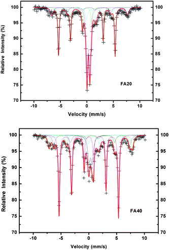 | ||
| Fig. 3 Mössbauer spectroscopy patterns of FA20 and FA40. | ||
The results indicate that there are different phases containing iron in the samples, and some of them could not be detected by XRD.
As shown in the MS results, all the samples displayed a magnetically split six-peak spectral component with an isomer shift (IS) of 0.00 mm s−1, quadrupole splitting (QS) of 0.00 mm s−1, and magnitude of the hyperfine field of 33 T, which can be identified as due to metallic iron with large grain size. New sextets appeared in FA20 to FA60, which can be associated with Fe3O4, as revealed by the well-defined magnetic sextet of the spectrum.25 Doublet(1) has an IS of (0.30–0.34) mm s−1 and QS of (0.53–0.59) mm s−1, which is typical of Fe3+ ions substituting for Al3+ ions in an alumina lattice.26 Doublet(2), with IS of (0.78–0.94) mm s−1 and QS of (1.67–2.01) mm s−1, represents Fe2+ in the FeAl2O4 spinel structure.27,28 From the XRD and Mössbauer spectroscopy results, we can obtain the final phase composition (Table 2) of the samples.
| Samples | Final phase composition (volume fraction) |
|---|---|
| FA10 | Fe1.12–(FeAl2O4)4.73–[(Fe0.07Al0.93)2O3]94.15 |
| FA20 | Fe4.38–(Fe3O4)3.04–(FeAl2O4)7.75–[(Fe0.085Al0.915)2O3]84.83 |
| FA40 | Fe11.72–(Fe3O4)13.32–(FeAl2O4)8.88–[(Fe0.097Al0.903)2O3]66.08 |
| FA50 | Fe13.43–(Fe3O4)21.80–(FeAl2O4)13.90–[(Fe0.095Al0.905)2O3]50.87 |
| FA60 | Fe18.61–(Fe3O4)25.46–(FeAl2O4)13.91–[(Fe0.12Al0.88)2O3]42.02 |
Microstructure
Element mapping and backscattered electron images are shown in Fig. 4, in which we can see the microstructure and the distribution of elements in our samples.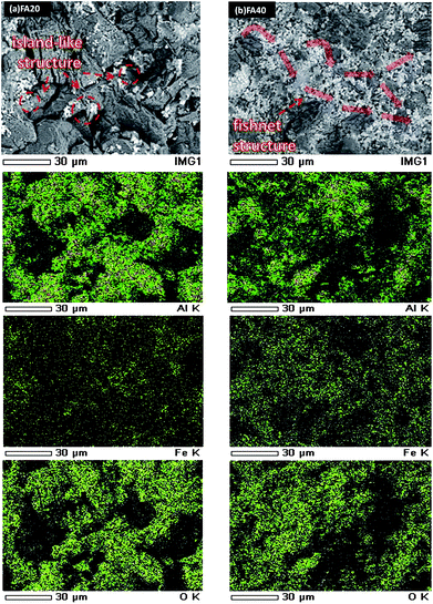 | ||
| Fig. 4 Backscattered electron images and corresponding element mappings of: (a) low conductor content sample (FA20), in which the Fe-rich structures are surrounded by an insulating phase, (b) high conductor content sample (FA40), in which the Fe-rich structures form a conductive path in the insulating matrix. | ||
In FA20, there are some island-like structures surrounded by the matrix. With increasing Fe content, a fishnet structure appears in FA40. Most of the island structures and fishnet structures are located at the grain boundary. According to the mapping results, there is a relatively high Fe element content in these areas, which can be considered as Fe-rich structures. As we can see from the backscattered electron images, the average size of each island-like structure is about 5 to 10 μm and the fishnet structure forms a conductive path in the matrix, with an average width of 10 μm. According to the XRD and MS results, Fe is one of the conductive phases in these structures, without any doubt. Compared with the typical dielectric phases (FeAl2O4 and Al2O3), Fe3O4, which has a relative high electrical conductivity at room temperature,29 also should be considered as a conductive phase in the Fe-rich structures. On the contrary, the dark grey area with a relatively high Al element content in Fig. 4 suggests an insulating matrix, which includes both FeAl2O4 and Al2O3 phases.
Electromagnetic results and discussion
The frequency (f) dispersions of the reactance (Z), permittivity (ε), and conductivity (σ) are shown in Fig. 5 and 6. The samples with a low content of conductive phase (FA10, FA20) show typical dielectric behaviour, a linear relationship between Z and f. In the samples with high conductive phase content (FA40, FA50 and FA60), the composites act as a metallic medium (ε < 0).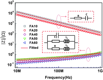 | ||
| Fig. 5 Frequency dependence of the reactance for the samples. The insets show the equivalent circuits. | ||
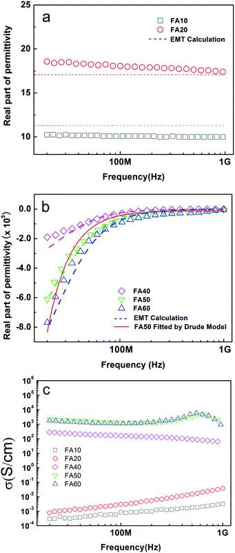 | ||
| Fig. 6 Frequency dependence of (a) the real part of the permittivity (ε′) in low conductor content samples and (b) the real part of the permittivity (ε′) in high conductor content samples. The dashed line is the calculated result based on EMT. Fitted results by the Drude model for sample FA50 are shown as the solid line. (c) The conductivity of each sample, calculated from the imaginary part of the permittivity (σ = ωε0ε′′). | ||
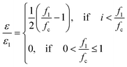
The origin of the dispersion is mostly ascribed to the conductive phase. In our composites, where the conductor and insulator components are interspersed with each other in a disordered manner, it is impossible to determine their electromagnetic response by solving Maxwell's equations because of the complicated boundary conditions.30 In such a case, one of the most widely used approaches is the Bruggeman effective medium theory (EMT).31 Based on the effective medium theory (EMT), the permittivity of conductor–insulator composites in the GHz range, where |εconductor| is much larger than ε of the insulator materials, can be described by the following equation,31
 | (1) |
Eqn (1) clearly indicates that the conductor–insulator composite acts as a dielectric medium for small conductive phase concentrations. Above the percolation threshold, the composite becomes a conductor because a continuous conductive path is formed across the sample, in which the electrons can move freely.
The percolation threshold has a close relationship with the particle shape and size.32,33 For randomly oriented cubes in three dimensions, the percolation threshold is about 0.22.34
The volume fraction of conductive phases in each sample can be obtained from the MS results. In FA10 and FA20, the conductive phase content is below the percolation threshold (1.12 vol.% in FA10 and 7.42 vol.% in FA20), meaning that the free electrons cannot move freely in the composite because of the insulating matrix (Fig. 7).
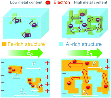 | ||
| Fig. 7 Schematic diagram showing the polarization of the dual composites with different metal content. In the low conductor content sample (left), Fe-rich structures are surrounded by the insulator matrix, and free electrons are localized. In the high conductor content sample (right), conductive paths are formed by Fe-rich structures, in which free electrons can move freely, leading to metallic behavior. E0 represents the external field, Ed is the polarization field due to the insulator matrix, and Ef denotes the field due to the localized free electrons. | ||
During the polarization process, the free electrons are localized in the conductive particles and move in the opposite direction to the external field (E0). This process is quite like electric polarization, which gives a good explanation of the typical dielectric behaviour and the higher dielectric constant compared to pure Al2O3 (dielectric constant = 9.3). According to the polarization mechanisms of dielectric materials, experimental spectra of the reactance (Z) for the low conductive phase samples have been fitted based on an equivalent circuit, which is composed of resistance R (ZR = R) and capacitance C (ZC = 1/2πfC) in series connection (Z = ZR + ZC). The fitting results show good agreement with the experimental spectra, indicating that the behaviour of Z and ε can be well explained by an RC series equivalent circuit in FA10 and FA20. For high conductive phase content samples above the percolation threshold (25.04 vol.% in FA40, 35.23 vol.% in FA50, and 44.07 vol.% in FA60), because of the formation of conductive paths in which the electrons can move freely (Fig. 7), we can consider the conductive path as an inductor L. So, we have used a equivalent circuit composed of resistance R, capacitance C, and inductor L to fit the reactance (Z) results for FA40, FA50, and FA60 (Fig. 5).
According to the EMT, the permittivity of a conductor–insulator composite can be described as follows,10
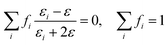 | (2) |
The calculated results for the permittivity are shown as dashed lines in Fig. 6(a) and (b). The results show a good agreement with the experimental data, indicating that the response to the external electric field in our samples can be well described by the EMT. Also, as in the EMT prediction,35,36 the conductor–insulator transition is observed in Fig. 6(c), FA10 and FA20 show typical insulator behaviour with low conductivity, and FA40, FA50, and FA60 show typical conductor behaviour with high conductivity.
Negative permittivity behaviour is observed in samples with high conductive phase content. In FA40, the real part of the permittivity is negative in the low-frequency range (20 MHz to 400 MHz), and it changes to positive when the frequency is higher than 400 MHz. The real part of the permittivity in FA50 and FA60 remains negative over the whole measurement range. This tendency indicates typical conductor-like behaviour, which can be well described and fitted by the Drude formula,37
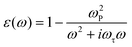 | (3) |
 | (4) |
In most cases, the Drude model is used to explain the interaction between free electrons and the electromagnetic field in a pure metal. The concentration of carriers in a metal usually remains in the order of 1023, which places the plasma frequency in the ultraviolet range (about 1015 to 1017 Hz). In our dual composites, the concentration of carriers can be controlled by adjusting the content of the conductive component, making the effective plasma frequency tunable in the GHz range and effectively reducing the energy loss. In the GHz range, ferromagnetic resonance can be excited by applying an external DC magnetic field to obtain negative permeability.18,38
Conclusions
In this paper, dual composites have been fabricated by selective reduction reaction. A conductor–insulator transition appears in the composites when the conductive phase content is above the percolation threshold (22 vol.%). After the transition, a tunable negative permittivity is observed in high Fe content samples in the GHz range, which can be well fitted by the Drude model. In our samples, the real part of the permittivity can be directly calculated by using effective medium theory (EMT), which shows good agreement with the experimental data. This kind of composite offers a feasible approach to fabricate DNMs by applying an external DC magnetic field to generate a ferromagnetic resonance and thus achieve negative permeability.The authors acknowledge the support of the National Natural Science Foundation of China (Grant no. 50772061, 51172131), the 973 Program (no. 2012CB825702), the Program for New Century Excellent Talents in University (no. NCET-10-518), the China Scholarship Council (CSC, 2011622096) and the Independent Innovation Foundation of Shandong University (no. IIFSDU-2010JQ002, GIIFSDU-YYX10011). The authors acknowledge use of facilities within the University of Wollongong Electron Microscopy Centre.
Notes and references
- V. G. Veselago, Sov. Phys. Usp., 1968, 10, 509 CrossRef.
- J. B. Pendry, Phys. Rev. Lett., 2000, 85, 3966–3969 CrossRef CAS.
- D. R. Smith and N. Kroll, Phys. Rev. Lett., 2000, 85, 2933 CrossRef CAS.
- R. A. Shelby, D. R. Smith and S. Schultz, Science, 2001, 292, 6 CrossRef.
- M. C. K. Wiltshire, J. B. Pendry, I. R. Young, D. J. Larkman, D. J. Gilderdale and J. V. Hajnal, Science, 2001, 291, 849 CrossRef CAS.
- Z. C. Shi, R. H. Fan, Z. D. Zhang, L. Qian, M. Gao, M. Zhang, L. T. Zheng, X. H. Zhang and L. W. Yin, Adv. Mater., 2012, 24, 2349 CrossRef CAS.
- T. J. Yen, W. J. Padilla, N. Fang, D. C. Vier, D. R. Smith, J. B. Pendry, D. N. Basov and X. Zhang, Science, 2004, 303, 1494 CrossRef CAS.
- S. Linden, C. Enkrich, M. Wegener, J. F. Zhou, T. Koschny and C. M. Soukoulis, Science, 2004, 306, 1351 CrossRef CAS.
- C. Enkrich, M. Wegener, S. Linden, S. Burger, L. Zschiedrich, F. Schmidt, J. F. Zhou, Th. Koschny and C. M. Soukoulis, Phys. Rev. Lett., 2005, 95, 203901 CrossRef CAS.
- W. Cai and V. Shalaev, Optical Metamaterials: Fundamentals and Applications, Springer Science+Business Media, LLC, USA, 2010, ch. 1 Search PubMed.
- N. Limberopoulos, A. Akyurtlu, K. Higginson, A. Kussow and C. D. Merritt, Appl. Phys. Lett., 2009, 95, 023306 CrossRef.
- J. Sun, J. Zhou, B. Li and F. Y. Kang, Appl. Phys. Lett., 2011, 98, 101901 CrossRef.
- S. T. Chui and L. Hu, Phys. Rev. B: Condens. Matter, 2002, 65, 144407 CrossRef.
- J. B. Pendry, Opt. Express, 2003, 11, 639 CrossRef CAS.
- A. Mukhopadhyay and R. I. Todd, J. Eur. Ceram. Soc., 2010, 30, 1359 CrossRef CAS.
- H.-Y. Lin, Y.-W. Chen and C. Li, Thermochim. Acta, 2003, 400, 61–67 CrossRef CAS.
- Q. Zhao, L. Kang, B. Du, H. Zhao, Q. Xie, X. Huang, B. Li, J. Zhou and L. Li, Phys. Rev. Lett., 2008, 101, 027402 CrossRef.
- A. Pimenov, A. Loidl, K. Gehrke, V. Moshnyaga and K. Samwer, Phys. Rev. Lett., 2007, 98, 197401 CrossRef CAS.
- C. E. Ciomaga, I. Dumitru, L. Mitoseriu, C. Galassi, A. R. Iordan, M. Airimioaei and M. N. Palamaru, Scr. Mater., 2010, 62, 610 CrossRef CAS.
- H. J. Zhao, L. Kang, J. Zhou, Q. Zhao, L. T. Li, L. Peng and Y. Bai, Appl. Phys. Lett., 2008, 93, 201106 CrossRef.
- B. Li, G. Sui and W. H. Zhong, Adv. Mater., 2009, 21, 4176 CrossRef CAS.
- S. Kohli, C. D. Rithner and P. K. Dorhout, Chem. Mater., 2002, 14, 3786 CrossRef CAS.
- M. Liu, H. B. Li, L. Xiao, W. X. Yu, Y. Lu and Z. D. Zhao, J. Magn. Magn. Mater., 2005, 294, 294 CrossRef CAS.
- Ch. Laurent, A. Peigney and A. Rousset, J. Mater. Chem., 1998, 8(5), 1263 RSC.
- L. F. Cótica and S. C. Zanatta, Solid State Ionics, 2004, 171, 283 CrossRef.
- A. Cordiera, A. Peigneya, E. De Graveb, E. Flahauta and C. Laurent, J. Eur. Ceram. Soc., 2006, 26, 3099 CrossRef.
- A. Paesano and C. K. Matsuda, J. Magn. Magn. Mater., 2003, 264, 264 CrossRef CAS.
- V. G. de Resende, A. Cordier, E. De Grave, C. Laurent, S. G. Eeckhout, G. Giuli, A. Peigney, G. M. da Costa and R. E. Vandenberghe, J. Phys. Chem. C, 2008, 112(42), 16256 CAS.
- M. T. Chang, L. J. Chou, C. H. Hsieh, Y. L. Chueh, Z. L. Wang, Y. Murakami and D. Shindo, Adv. Mater., 2007, 19, 2290 CrossRef CAS.
- V. Shalaev, Nonlinear Optics of Random Media: Fractal Composites and Metal-Dielectric Films, Springer, Berlin, 2000 Search PubMed.
- D. A. G. Bruggeman, Ann. Phys., 1935, 24, 636 CrossRef CAS.
- R. Consiglio, D. R. Baker, G. Paul and H. E. Stanley, Physica A, 2003, 319, 49 CrossRef.
- U. Alon, A. Drory and I. Balberg, Phys. Rev. A, 1990, 42, 8 CrossRef.
- D. R. Baker, G. Paul, S. Sreenivasan and H. E. Stanley, Phys. Rev. E: Stat., Nonlinear, Soft Matter Phys., 2002, 66, 046136 CrossRef.
- J. H. Zhu, Z. P. Luo, S. J. Wu, N. Haldolaarachchige, D. P. Young, S. Y. Wei and Z. H. Guo, J. Mater. Chem., 2012, 22, 835 RSC.
- C. Pecharroman and J. S. Moya, Adv. Mater., 2000, 12, 4 CrossRef.
- Z. C. Shi, R. H. Fan, Z. D. Zhang, H. Y. Gong, J. Ouyang, Y. J. Bai, X. H. Zhang and L. W. Yin, Appl. Phys. Lett., 2011, 99, 032903 CrossRef.
- M. Mizuguchi and K. Takanashi, J. Phys. D: Appl. Phys., 2011, 44, 064007 CrossRef.
| This journal is © The Royal Society of Chemistry 2013 |