Multiple nematic phases observed in chiral mesogenic dimers†
Anna
Zep
a,
Satoshi
Aya
b,
Kenji
Aihara
c,
Kenji
Ema
c,
Damian
Pociecha
a,
Karolina
Madrak
a,
Piotr
Bernatowicz
d,
Hideo
Takezoe
b and
Ewa
Gorecka
*a
aUniversity of Warsaw, Department of Chemistry, ul. Żwirki i Wigury 101, 02-089 Warsaw, Poland. E-mail: gorecka@chem.uw.edu.pl
bDepartment of Organic and Polymeric Materials, Tokyo Institute of Technology, O-okayama, Meguro-ku, 152-8552, Tokyo, Japan
cDepartment of Physics, Tokyo Institute of Technology, O-okayama, Meguro-ku, 152-8551, Tokyo, Japan
dInstitute of Physical Chemistry, Polish Academy of Sciences, Kasprzaka 44/52, 01-224 Warsaw, Poland
First published on 9th November 2012
Abstract
A sequence of seven nematic phases has been observed in chiral mesogenic dimers, having odd number of carbon atoms in the spacer, thus a bent shape. The highest temperature phase is a chiral nematic (cholesteric) phase on heating or blue phases on cooling. The lowest temperature nematic phase expels the chiral twist and exhibits spontaneous bent–splay modulation.
The nematic liquid crystalline phase (NLC) is the most commonly used liquid crystal in various applications. It is considered as a ‘simple’ phase in contrast to the ‘complex’ smectic or columnar liquid crystals (LC). In recent years this common knowledge about the nematic phase has started to be perturbed by reports about biaxial and orientationally modulated NLCs. In this paper we add another phase to the family of NLCs. By definition a nematic phase has a long-range orientational order of the molecular axes but only a short range positional order. The orientational order parameter,
 , where β is the angle between the long molecular axis and the director (average direction of the long molecular axis), is usually lower than 0.5 and the positional order extends only up to 1–2 molecular lengths, which is the typical correlation length for liquids. This simple picture of the nematic phase might be influenced by the introduction of chirality, biaxiality, or unusual values of physical parameters such as elastic constants. If the constituting molecules are chiral, the neighboring molecules spontaneously twist one against another that leads to the cholesteric (chiral nematic, N*) phase having a simple helical structure with a unique helical axis, or to the blue phase (BP), the cubic structure of which, formed by local double twist cylinders, is stabilized by defects.1 The frustrated nature of BP makes it stable usually only in a narrow temperature range.2 The nature of the nematic phase can also be influenced by fluctuations of ‘neighboring’ smectic phases; for some systems with the N phase separating smectic phases (re-entrant N phase) the phase transition between nematics with different type fluctuations was observed.3,4 Moreover, experimental claims were made that the N phase can be biaxial when built from bent-core molecules,5–7 and even more exotic N phases were theoretically predicted for unique molecular architectures.8 Recently for some dimeric molecules the transition between uniform N and space modulated N phases has been suggested.9,10
Here we describe multiple N–N phase transitions observed for chiral asymmetric dimers (Fig. 1), built of cholesterol and N-benzylidene-p-toluidine units connected by a flexible alkyl spacer (synthesis described in the ESI†). The phase transition temperatures and enthalpies for all studied homologues are given in Table 1. For dimers with even number of carbon atoms in the spacer either only the N* phase (n = 10) or N* and smectic A phases (n = 4, 6) were observed on cooling as confirmed by optical, DSC and X-ray studies. Odd spacer dimers exhibit only liquid crystalline phases with short range positional order with no sign of the existence of smectic phases, as confirmed by the X-ray studies.
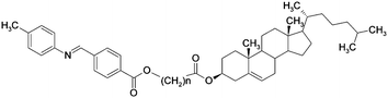 | ||
| Fig. 1 General molecular structure of studied dimers. | ||
| n | m.p. | SmA | N2 | N* | Iso | |||
|---|---|---|---|---|---|---|---|---|
| a Detected only by optical and X-ray measurements. | ||||||||
| 3 | 112.3 (37.0) | • | 55.1 (0.7) | • | 67.7 (0.2) | • | ||
| 4 | 127.9 (33.2) | • | 146.9 (0.8) | • | 191.8 (4.9) | • | ||
| 5 | 92.5 (48.7) | • | 67.9 (0.3) | • | 102.3 (0.8) | • | ||
| 6 | 152.3 (49.0) | • | 120a | • | 158.4 (5.3) | • | ||
| 7 | 83.0 (49.6) | • | 75.7 (0.4) | • | 110.8 (1.1) | • | ||
| 9 | 81.2 (44.2) | • | 75.7 (0.4) | • | 113.6 (1.6) | • | ||
| 10 | 82.7 (49.3) | • | 137.5 (4.6) | • | ||||
| 15 | 62.9 (26.6) | • | 63.2 (0.3) | • | 107.9 (2.5) | • | ||
Let us first describe the X-ray diffraction (XRD) data. For all compounds the X-ray pattern in the nematic phase shows two weak, diffused signals at a small angle region (Fig. 2), corresponding to L and L/2, where L is the length of a fully stretched dimeric molecule. The situation is the same for homologues with even and odd numbers of carbon atoms in the spacer (see ESI†). The appearance of the signal corresponding to the half molecular length suggests that molecules locally intercalate,11 so the mean distance between molecular mass centres along the director is close to L/2. The intercalated structure becomes more favourable for compounds with mesogenic units separated by a longer alkyl spacer11 as the fluctuations with the wavelength L weaken with elongation of the alkyl linkage between mesogenic units. For even homologues n = 4 and 6, on cooling the fluctuations with wavelength corresponding to L/2 condense to form a long range ordered structure of intercalated smectic A phases. For odd homologues both fluctuations are only weakly temperature dependent.
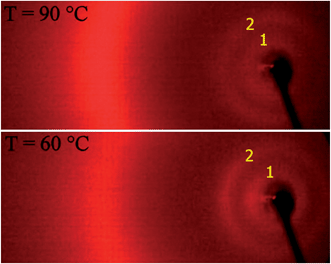 | ||
| Fig. 2 X-ray patterns for N* (top) and N2 (bottom) phases for dimer n = 5. Signals marked with 1 and 2 correspond to full and half molecular lengths, L and L/2, respectively. | ||
Although there are no clear changes of X-ray patterns with temperature for odd homologues (Fig. 2), the optical and calorimetrical investigations show distinct phase transitions. By the conventional DSC measurements only one broad signal of nematic–nematic phase transition was found, with small temperature hysteresis and transition enthalpy independent of cooling or heating scans. The miscibility studies confirmed that while the upper temperature N* phase (on heating) is conventional cholesteric phase, the lowest temperature N2 phase is not. The temperature stability of the N2 phase abruptly decreases upon adding a reference material exhibiting only the N* phase (see ESI†).
Close examination of the N*–N2 phase transition temperature region by the high resolution calorimetry revealed additional phase transitions (Fig. 3); there are actually up to 5 intermediate phases between N* and N2. They are separated by distinct first order phase transitions, which are well reproducible in consecutive scans. Such sequential N–N transitions are most probably the manifestation of frustration in the system, resulting from competing interactions that stabilize the N* and the N2 phases. Since the total temperature range of all intermediate phases is below 2 K, which makes their investigations difficult, we focus our studies mainly on N* and N2 phases. The upper temperature nematic phase formed on heating exhibits a typical N* texture, with characteristic oily streaks and strong optical activity. The N* phase transforms into the blue phase in a narrow temperature range before making the transition to the isotropic phase. However, on cooling from the isotropic phase the BP texture (Fig. 4a) exists over a wide temperature range of about 30 degree, allowing direct BP–N2 phase transition.
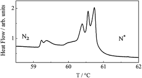 | ||
| Fig. 3 High resolution DSC scan for dimer n = 15 showing multiple phase transitions in the region between N* and N2 phases. All five intermediate phases are also nematics. | ||
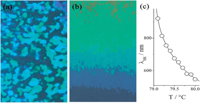 | ||
| Fig. 4 BP and N* phase textures observed for dimer n = 7, at the same temperature, depending on the sample history: (a) platelet textures of cubic BP formed upon cooling from the isotropic phase and (b) the N* phase formed upon heating from the N2 phase, the colors are due to selective reflection in the cell with small temperature gradient. (c) Selective reflection wavelength vs. temperature in the N* phase. | ||
Such an unusually broad range of BP has been already reported in many systems: T-shaped molecules,12 chiral dimers possessing an achiral bent core and chiral rod-like segment,13 achiral dimers with a chiral dopant,14 bent-core nematics with a chiral dopant,15 and rod- and bent-core mixtures with a chiral dopant.16 The important conformational characteristic for such systems is a bent shape, which makes some elastic constants lower.16,17 It was theoretically shown that a small value of bend elastic constant K33 enhances the stability of BP.18 The same stabilization mechanism is effective in the present molecules; the dimers linked by a spacer with odd carbon numbers are bent shaped.
The transition from N* to N2 (the sample is heated a few degrees celsius above the N2–N* transition and subsequently cooled) is accompanied by critical unwinding of the helix in the N* phase on approaching the transition point that can be monitored by temperature changes of selective reflection wavelengths (Fig. 4b and c). In the N2 phase a birefringent, but optically inactive texture is formed in thin cells (up to 5 microns) with planar anchoring. In thicker cells often a homeotropic texture is observed, proving that the phase is optically uniaxial. No measurable optical activity confirms that the N2 phase expels the spontaneous chiral twist.
In thin planar cells sequential texture changes can be seen over a 1–2 degree temperature range just below N* (see ESI†); at first a nearly uniform texture is observed, having the optical axis perpendicular to the rubbing direction, suggesting that most molecules orient their long axis perpendicular to the rubbing direction, then the molecules reorient, and this process is accompanied by formation of stripes perpendicular to the rubbing direction; between the stripes the optical axis rotates by π. Upon further cooling the stripes gradually disappear. Such texture changes can be attributed to the sequential phase transitions, observed in high resolution DSC. Finally areas with the optical axis parallel to the rubbing direction cover the whole sample. Although this texture seems to be uniform, at high magnification another system of fine stripes, perpendicular to the rubbing direction, can be detected (Fig. 5a) with periodicity depending on the cell thickness (it is 1.5, 2.5 and 3.5 micron in the 1.7, 3.3 and 5 micron thick cells).
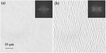 | ||
| Fig. 5 (a) System of stripes in the N2 phase of homologue n = 15 in a 3 micron thick cell just below the phase transition from the N* phase, observed with light polarized along the rubbing direction. (b) Two systems of stripes inclined from the initial direction, observed in the N2 phase, few degrees below the phase transition. In the insets Fourier transform of the optical pattern is shown. | ||
This system of stripes is formed due to the small alternation of birefringence, the difference between the areas of lowest and highest birefringence is ∼0.01. Focusing lower or upper sample surfaces causes shifting of the stripes position by half of their periodicity. The stripes are detected in polarized light only if incident polarization is along the rubbing direction, they are not visible if the polarization is perpendicular to the rubbing direction.
Evidently, the stripes are formed due to the deflection of the optical ray direction by the structure with periodic modulations of extraordinary refractive index and focusing at upper and lower planes.19 They disappear when a small dc voltage (∼3–4 V in a 3 micron cell) is applied across the sample thickness, with a clearly defined, slightly temperature dependent threshold. Summarizing all these information we propose the model in which stripes are formed because the director is bend–splay modulated in the bulk of the sample and anchored uniformly at the surfaces to the rubbing direction (Fig. 6). It should be noticed that the proposed director structure is similar to this attributed to Williams domains formed at electrohydrodynamic instability in the N phase.20 The linear dependence between cell thickness and stripe periodicity is also the same as for the Williams domains.21
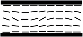 | ||
| Fig. 6 Model of director structure in the N2 phase responsible for the stripe texture in the planar cell, the director is bend–splay modulated in the bulk of the sample and anchored at the surfaces to the rubbing direction. The stripes are observed due to the focusing of light by the structure with periodically modulated refractive index. | ||
In order to clear up the nature of the N2 phase further, polarized IR, dielectric and solid state 13C NMR studies were performed (see ESI for details†). In dielectric measurements we confirmed that homologues studied here have negative dielectric anisotropy, but this seems not a necessary condition to observe spontaneous bend modulations, as the N*–N2 phase transition can be found also for similar dimers with a strong terminal dipole moment thus a positive dielectric anisotropy.22 By the polarized IR spectroscopy method the intensity of phenyl stretching and CH2 stretching was monitored in the N2 phase, both absorption bands have a very small anisotropy, confirming that the director has a periodic structure averaging to some extent the directions of mesogenic groups and alkyl chains. This result is also consistent with 13C NMR data, showing that the averaging effect takes place also in the bulk sample.
Apparently, materials studied here show the spontaneous symmetry breaking into domains with both the positive and negative bend deformation. Such symmetry breaking was predicted for compounds with a negative bend elastic constant, K33, by Dozov for molecules having a non-linear mesogenic core.23 However, the bend structure proposed by Dozov inevitably implies biaxiality, while experimentally the N2 phase seems to be optically uniaxial. This inconsistency can be explained if we assume that the correlation for direction of spontaneous bent is only short range. Despite this, in planar cells the bent structure becomes visible because surfaces induce additional alignment of the director. Apparently, related to our work, a spontaneously modulated nematic phase has been described recently in ref. 9 and 10. But it should be stressed that the modulated structure reported here is actually different. In our case stripes are formed perpendicular to the rubbing direction and they are due to the focusing of light on the bend–splay modulated director structure. Panov et al.10 described ‘stripes’ being parallel to the rubbing direction, resulting from twist–splay director modulations. Cestari et al.9 suggested spontaneous twist–bent deformation for the nematic phase, however in their case the periodic structure of the nematic phase resulted in a stripe texture consisting of elongated focal conics.
Finally it should be mentioned that on cooling the system few degrees below the transition to the N2 phase, parallel stripes evolve continuously into a more complex structure that can be viewed as two systems of stripes symmetrically tilted from the initial direction (Fig. 5b). This phenomenon will be the subject of further investigations.
Conclusions
For the first time a liquid crystalline system is reported showing the phase transition between nematic phases having spontaneous twist (N* phase) induced by chirality of constituting molecules and spontaneous bend (N2 phase) enforced by the shape of constituting molecules. We can speculate that the multiple intermediate nematic phases observed in the short temperature range between N* and N2 nematic phases have the structures exhibiting simultaneous twist and bend, which are either commensurate or incommensurate.Acknowledgements
The authors wish to acknowledge the FNP Project TEAM/2010-5/4, Self-assembly of functionalized inorganic–organic liquid crystalline hybrids for multifunctional nanomaterials, for financial support. Special thanks to Prof. G. Y. Yeap for drawing our attention to dimeric mesogens and valuable discussions.Notes and references
- P. P. Crooker, Mol. Cryst. Liq. Cryst., 1983, 98, 31 CrossRef CAS.
- H. Kikuchi, Struct. Bonding, 2008, 128, 99 CrossRef CAS.
- G. S. Iannacchione, C. W. Garland, J. Mieczkowski and E. Gorecka, Phys. Rev. E: Stat. Phys., Plasmas, Fluids, Relat. Interdiscip. Top., 1998, 58, 595 CrossRef CAS.
- G. N. Nounesis, S. Kumar, S. Pfeiffer, R. Shashidhar and C. W. Garland, Phys. Rev. Lett., 1994, 73, 565 CrossRef CAS.
- G. Y. Hyung, K. Shin-Woong, R. Y. Dong, A. Marini, K. A. Suresh, M. Srinivasara and S. Kumar, Phys. Rev. E: Stat., Nonlinear, Soft Matter Phys., 2010, 81, 051706 CrossRef.
- B. R. Acharya, A. Primak, T. J. Dingemans, E. T. Samulski and S. Kumar, Pramana, 2003, 61, 231 CrossRef CAS.
- N. Vaupotic, J. Szydlowska, M. Salamonczyk, A. Kovarova, J. Svoboda, M. Osipov, D. Pociecha and E. Gorecka, Phys. Rev. E: Stat., Nonlinear, Soft Matter Phys., 2009, 80, 030701 CrossRef CAS.
- K. Trojanowski, G. Pajak, L. Longa and T. Wydro, Phys. Rev. E: Stat., Nonlinear, Soft Matter Phys., 2012, 86, 011704 CrossRef.
- M. Cestari, S. Diez-Berart, D. A. Dunmur, A. Ferrarini, M. R. de la Fuente, D. J. B. Jackson, D. O. Lopez, G. R. Luckhurst, M. A. Perez-Jubindo, R. M. Richardson, J. Salud, B. A. Timimi and H. Zimmermann, Phys. Rev. E: Stat., Nonlinear, Soft Matter Phys., 2011, 84, 031704 CrossRef CAS.
- V. P. Panov, M. Nagaraj, J. K. Vij, Yu. P. Panarin, A. Kohlmeier, M. G. Tamba, R. A. Lewis and G. H. Mehl, Phys. Rev. Lett., 2010, 105, 167801 CrossRef CAS.
- T.-N. Chan, G.-Y. Yeap, W.-S. Yam, K. Madrak, A. Zep, D. Pociecha and E. Gorecka, J. Mater. Chem., 2012, 22, 11335 RSC.
- A. Yoshizawa, M. Sato and J. Rokunohe, J. Mater. Chem., 2005, 15, 3285 RSC.
- C. V. Yelamaggad, I. S. Shashikala, G. Liao, D. S. Shankar Rao, S. K. Prasad, Q. Li and A. Jakli, Chem. Mater., 2006, 18, 6100–6102 CrossRef CAS.
- H. J. Coles and M. N. Pivnenko, Nature, 2005, 436, 997 CrossRef CAS.
- S. Taushanoff, K. V. Le, J. Williams, R. J. Twieg, B. K. Sadashiva, H. Takezoe and A. Jakli, J. Mater. Chem., 2010, 20, 5893 RSC.
- S.-T. Hur, M.-J. Gim, H.-J. Yoo, S.-W. Choi and H. Takezoe, Soft Matter, 2011, 7, 8800 RSC.
- P. Sathyanarayana, M. Mathew, Q. Li, V. S. S. Sastry, B. Kundu, K. V. Le, H. Takezoe and S. Dhara, Phys. Rev. E: Stat., Nonlinear, Soft Matter Phys., 2010, 81, 010712(R) CrossRef.
- J. Fukuda, Phys. Rev. E: Stat., Nonlinear, Soft Matter Phys., 2012, 85, 020701(R) Search PubMed.
- K. Kondo, M. Arakawa, A. Fukuda and E. Kuze, Jpn. J. Appl. Phys., 1983, 22, 394 CrossRef.
- P. A. Penz, Phys. Rev. Lett., 1970, 24, 1405 CrossRef CAS.
- S. Hirata and T. Tako, Jpn. J. Appl. Phys., 1982, 21, 675 CrossRef CAS.
- Similar dimeric mesogens with polar end groups and showing N–N phase transition were recently synthesised by G. Y. Yeap’s group and studied by the Warsaw group. The results will be published in a separate paper by the Penang University group.
- I. Dozov, Europhys. Lett., 2001, 56, 247 CrossRef CAS.
Footnote |
| † Electronic supplementary information (ESI) available: Synthetic procedures and characterization data of all new compounds, description of methods used, miscibility studies, optical textures, X-ray, dielectric and 13C NMR studies. See DOI: 10.1039/c2tc00163b |
| This journal is © The Royal Society of Chemistry 2013 |