Naturally occurring iron oxide nanoparticles: morphology, surface chemistry and environmental stability
Haibo
Guo
a and
Amanda S.
Barnard
*b
aSchool of Materials Science and Engineering, Shanghai University, Shanghai, China
bVirtual Nanoscience Laboratory, Division of Materials Science and Engineering, CSIRO, Parkville, Victoria 3052, Australia. E-mail: amanda.barnard@csiro.au; Tel: +61-3-9662-7356
First published on 16th November 2012
Abstract
The widespread nanostructures of iron oxides and oxyhydroxides are important reagents in many biogeochemical processes in many parts of our planet and ecosystem. Their functions in various aspects are closely related to their shapes, sizes, and thermodynamic surroundings, and there is much that we can learn from these natural relationships. This review covers these subjects of several phases (ferrihydrite, goethite, hematite, magnetite, maghemite, lepidocrocite, akaganéite and schwertmannite) commonly found in water, soils and sediments. Due to surface passivation by ubiquitous water in aquatic and most terrestrial environments, the difference in formation energies of bulk phases can decrease substantially or change signs at the nanoscale because of the disproportionate surface effects. Phase transformations and the relative abundance are sensitive to changes in environmental conditions. Each of these phases (except maghemite) displays characteristic morphologies, while maghemite appears frequently to inherit the precursor's morphology. We will see how an understanding of naturally occurring iron oxide nanostructures can provide useful insight for the production of synthetic iron oxide nanoparticles in technological settings.
1. Introduction
The materials chemistry of nanoscale structures is a topic of intense and widespread research, and significant investment is directed toward developing reliable techniques to engineer nanomaterials indirectly, by controlling the surrounding chemistry. Specific precursors, solvents and surfactant are routinely employed, in combination with prescribed temperatures, pressures, or both. The origins of this approach begins with observations of naturally occurring nanomaterials and the geological or biogenic processes involved, which are (in many ways) more advanced than our own.1–3 Nanoparticles and more complex nanostructures (such as nanopores or nanoframes) are formed and reside in many different parts of the environment, and in their inhabitants. There is still much that we can learn from studying how natural nanomaterials evolve and mature, and how their size, shape and phase are related to their surrounding chemistry.The elemental abundance of oxygen, hydrogen and iron at the surface and in the Earth's crust has fostered widespread occurrences of iron oxides and oxyhydroxides in a diverse range of aquatic and terrestrial environments. Ten of the 14 known iron oxides and oxyhydroxides are known to occur in nature, with hematite (Fig. 1a), magnetite (Fig. 1b) and goethite (Fig. 1c) being the most abundant as rock-forming minerals; ferrihydrite, maghemite (Fig. 1d) and lepidocrocite (Fig. 1e) being intermediately abundant in many locations; and wüstite, akaganéite, feroxyhyte, and bernalite being the least abundant.4 A number of bio-geochemical processes involve iron oxides and oxyhydroxides, which function as electron sinks or donors, absorbents, nutrients, and magnetotaxis and magnetoreceptors. Iron cycling, which generally starts from Fe(II)-containing primary rocks (e.g. pyrite), is common and active in many parts of ecosystems, such as marine5 and sedimentary environments.6 In these processes, various nanostructures of iron oxides and oxyhydroxides form and persist under certain conditions, especially at redox and pH interfaces. Based on surveys of the global budget of inorganic nanoparticles,7 naturally occurring iron oxide nanostructures may be 105 Tg (teragram or 1012 g) by mass in soils, assuming they only account for one percent of inorganic nanoparticles. Redistribution of nanostructured iron oxides by wind, rivers and glaciers, and ocean currents may contribute to Tg scale flux annually.
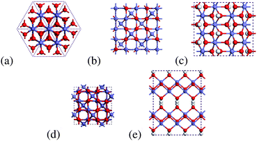 | ||
| Fig. 1 Schematic representation of the most abundant iron oxide and oxyhydroxides: (a) hematite, (b) magnetite, (c) goethite, (d) maghemite, and (e) lepidocrocite. Ferrihydrite is not shown as the structure is still under debate in the literature. All structures are viewed from the 〈001〉 or 〈0001〉 directions. | ||
Nanoparticulate iron oxides and oxyhydroxides, due to their large surface area and high chemical activity, contribute significantly to the immobilization of heavy metals (by adsorption or incorporation), the variation of pH and redox potential, Eh (through biogeochemical reactions), and the provision of essential nutrients to animals and plants, especially in Fe-deficient open oceans. For example, heavy metals such as As and U are toxic to the biosphere, but may be exposed by activities such as mining, and iron oxide nanostructures are known to scavenge these toxins effectively. For all these activities, their nanomorphologies and crystallinity are important factors in determining their activity and efficiency. It has been shown that the adsorption capacities of As and U by ferrihydrite decrease remarkably with either increasing crystallinity or transformation to more crystalline phases (such as goethite or hematite).8–10 As another example, the morphology of hematite nanoparticles was found to influence the bioactivity of iron-reducing bacteria (Shewanella oneidensis MR-1).11
Low-temperature environmental conditions and places that have high degrees of supersaturation of different elements are believed to be conducive to the formation and retention of large quantities of nanoparticles.1 The supersaturation is typically created by changing the physical and chemical conditions, such as influx of Fe(II)-rich hydrothermal vent fluids, mixing of highly acidic solutions with neutral pH water, and the evaporation of soil solutions.1 Once formed, iron oxide and oxyhydroxide nanoparticles are redistributed by rivers, glaciers, winds, and ocean currents into various ecosystems,7 where they can undergo continuous phase transformations, dissolution, and morphology changes. Fig. 2 shows four nanophases of iron oxides (ferrihydrite, goethite, schwertmannite, and hematite) found in terrigenous sediments carried by glaciers and icebergs.
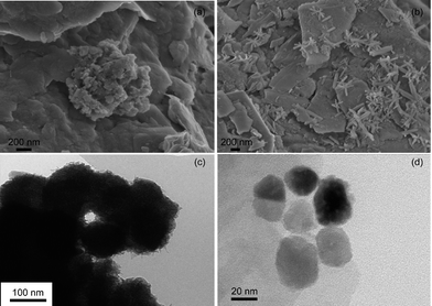 | ||
| Fig. 2 Iron oxide nanoparticles in iceberg-hosted sediments: (a) irregular shaped aggregate of ferrihydrite, (b) acicular twinned goethite, (c) schwertmannite pin-cushion spheroidal aggregates, and (d) hematite nanoparticles of irregular rounded shapes. (a–c) are from ref. 12, Copyright (2011), (d) is from ref. 13, Copyright (2011); both with permissions from Elsevier. | ||
The physical and chemical conditions of waters differ in temperature, pH, concentration of ions, supersaturation of oxygen, content of organic matter, and redox potential (Eh). The temperatures of surface waters undergo seasonal and regional variations, mostly below 35 °C. In deep-sea hydrothermal venting fluids the temperature may reach 400–500 °C under hundreds of bars hydraulic pressure.14,15 The pH ranges from very alkaline to strongly acidic (for example, the pH of acid mine drainage can be negative16). The concentrations of various ions, supersaturation of oxygen, flux of organic matter, and redox potential vary with places and depths. All these conditions also influence microbial activities and, therefore, the phases and morphologies of biotic iron oxides.
Soils are heterogeneous arrangements of solid matter and pores filled with gaseous (soil air) and aqueous (soil solution) phases,17 in addition to organic matter, microbes and other organisms. Their temperatures are generally below 60 °C (as in arid tropics), but may temporarily reach several hundreds of Celsius degrees in rare events of wild fires. Forest fires generate ash which leads to high pH (as high as 10) environments, which, together with the long-time participation of microbes, modify the iron oxides in top soil.18 The microenvironmental conditions in soil pores and solutions, including partial pressures of O2 and CO2, redox potential, and humidity vary largely with space and time. High-temperature processes, such as volcanic ash plumes which were mentioned as one of the primary major sources of naturally occurring inorganic nanoparticles (other primary major sources are soils and sediments, deep-sea hydrothermal vents which are outlets of underwater volcanoes, and sea spray which is aerosol generated by wave tip bursting),7 may be less significant for the formation of iron oxide nanoparticles compared to low-temperature environments. This makes the materials chemistry of iron oxides unique, and topical as we strive to learn more about the naturally occurring nanoparticles in the environment.
Therefore, in this review we will provide an overview and insight into the relationship between stability, morphology and the natural environments of water and soils where iron oxide nanoparticles are frequently found, paying specific attention to how the surrounding chemistry and conditions give rise to specific materials, and to different morphologies. We will focus on the most ubiquitous materials, and those that consistently occupy the nanoscale (Table 1). As there have previously been numerous reviews published on the synthesis and characterization of engineering iron oxide nanoparticles,19,20 we restrict our attention to naturally occurring samples (detailed in individual sections), but will draw from sources in the fields of chemistry, materials science, geology and computational physics.
| Solid phase | Typical size (nm) | Shape | Environments | Ref. |
|---|---|---|---|---|
| Ferrihydrite (Fe5HO8·4H2O) | 2–10 | Irregular and spherical | Near aerated waters and soils, and biota | 4, 17, 21, 22 |
| Goethite (α-FeOOH) | A few nm to macroscopic | Acicular | Soils, waters (both alkaline and acidic) | 17,21 |
| Hematite (α-Fe2O3) | Several nm to macroscopic | Rounded and rhombohedral | (Hot dry) soils, waters | 17 |
| 100 nm to macroscopic | Platy | High-temperature processes | 17, 23 | |
| Magnetite (Fe3O4) | Several nm to macroscopic | Octahedron, rhombo-dodecahedron | Anoxic soils and sediments, biota | 17 |
| Maghemite (γ-Fe2O3) | Not reported | Variable depending on precursor | Soils | 17 |
| Lepidocrocite (γ-FeOOH) | Not reported | Lath-like or tabular | Cool wet soils, waters | 17, 24 |
| Akaganéite (β-FeOOH) | Not reported | Lath-like, spindle, or rod | Chloride- or fluoride-rich solutions | 17, 25–27 |
| Schwertmannite (Fe8O8(OH)6(SO)n·H2O) | Not reported | Hedgehog or pin-cushion like | Sulfate-rich acid mine drainage | 17, 28–32 |
2. Individual iron oxide nanostructures
2.1. Ferrihydrite
Ferrihydrite is an iron oxyhydroxide mineral with the approximate composition Fe5HO8·4H2O.17 It is a poorly crystalline (but not amorphous) phase containing a high density of defects (vacancies, stacking faults), and variable water or hydroxyl adsorption or incorporation. Ferrihydrite occurs exclusively as a nanomaterial whose particulate size seldom exceeds 10 nm.33 The lack of long-range ordering makes it difficult for diffraction techniques, such as X-ray diffraction (XRD), to deliver a definite structure model except two to 6–8 broad peaks (see Fig. 3). These are given the descriptive names of 2-line or 6-line ferrihydrite as indicators of crystallinity because the fewer and broader the peaks are, the poorer the crystallinity is.4,17,34 Progress has been made in understanding the coordination of Fe and linkage of Fe–(O,OH) octahedra in ferrihydrites,35–40 as well as the electronic structure41 and surface modelling of ferrihydrite.42 However, the structure models of ferrihydrite are still under discussion.43–47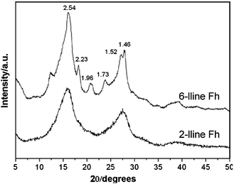 | ||
| Fig. 3 X-ray diffraction patterns (Mo Kα radiation) of ferrihydrite. The numbers are inter-planar distances in Ångstrom. Reprinted from ref. 40, Copyright (2009), with permission from Elsevier. | ||
Ferrihydrite is widespread in surface and recent geological environments.17,21 It has been found in many locations around the world,4 typically in, at, or near aerated surfaces of soils, rivers, lakes, and both hydrothermal and cold springs. Naturally occurring ferrihydrites are mostly associated with bacterial activities, either iron-oxidizing bacteria in aerated environments or iron-reducing bacteria in anaerobic environments. Biotic ferrihydrites may be of biogenic (biologically controlled and regulated) and abiogenic (byproduct of biological activities) origins. This is sometimes referred to as biologically induced. Large amounts of poorly ordered 2-line ferrihydrite deposits from hydrothermal vents (e.g. the Axial Volcano along the Juan de Fuca Ridge22) were identified to have an abundance of bacterial structures resembling Gallionella ferruginea, Leptothrix ochracea, and PV-1 filaments encrusted with nanoparticulate ferrihydrite. The ferrihydrites found in hydrothermal vents were identified to be abiogenic and to have mixed-valence Fe, with impurities (P, Si, Ca, N, and Ni).48 Ferrihydrites found in cave-seep deposits were found to also attach onto the microbial genera Gallionella and Leptothrix.49 Biotic ferrihydrite has been shown to be resilient against a phase transition into hematite upon heating at 80 °C in solution (aqueous heating experiments), in contrast to synthetic ferrihydrite which is absent of bacteria.22 The inhibitory effect was attributed to microbial surface functional groups that eliminated the aggregation and rotation of particles required for crystal growth.22 However, not all ferrihydrite nanoparticles attached to bacterial cells are biotic as they might be formed somewhere else and attracted to the bacteria.50
By Ostwald's Rule, a solid phase first formed via crystallization of a melt or a solution will have the lowest interfacial free energy, which may not be the most stable by bulk thermodynamics.51 Accordingly, due to its metastable nature, ferrihydrite is usually the first solid phase of iron oxides to precipitate, and is an important precursor of other iron oxides. Kinetics are important in the formation and retention of ferrihydrite, which relies on fast oxidation, fast precipitation, and stabilizing species in the environment. In aerated and alkaline environments, the low solubility of Fe(III) and fast oxidation rate favor ferrihydrite formation, while in microaerobic and neutral or acidic environments, the formation of ferrihydrite is generally mediated or produced by iron-oxidizing bacteria.
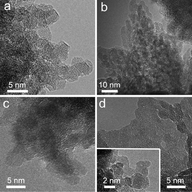
Individual ferrihydrite particles generally have narrow size distributions, usually 2–7 nm, and have irregular to spherical, or semi-euhedral morphologies.21Fig. 4 shows an aggregate of ferrihydrite nanocrystals which display this typical morphology. The aggregation patterns vary from spheres to spikes and needles (Fig. 5), but are mostly oriented with their close-packed oxygen layers parallel.21,52 The ferrihydrites found in hydrothermal vents were identified to be poorly ordered 2-line phase, consisting of nanoparticles with irregular shapes and sizes below 7 nm.48 The ferrihydrite found in abandoned coal mine drainages (rich in iron and sulfate) had similar morphologies and aggregates into large spheres (∼100 nm).53 The 2-line ferrihydrite nanocrystals collected from an acid mine drainage (pH = 4.4) were mainly sub-spherical to pseudo-hexagonal nanoparticles, 2–5 nm in diameter, and heavily aggregated to form electronically dense and irregular-shaped masses.29
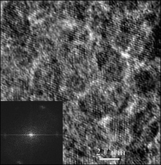 | ||
| Fig. 4 HRTEM image of an aggregate of ferrihydrite nanocrystals showing lattice fringes and inter-particulate regions. The inset shows the Fourier transforms. From ref. 52, Copyright (2000), reprinted with permission from AAAS. | ||
 | ||
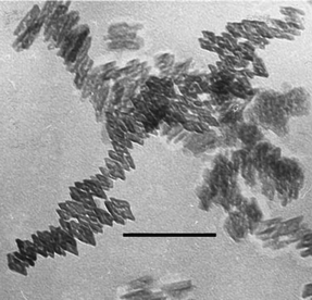
| Fig. 5 Typical TEM images of oriented attachments of ferrihydrite nanocrystals: (a) small needle, (b) large spike, (c) needle with a branch, and (d) sheet. Reprinted from ref. 21, Copyright (2012), with permission from Pan Stanford Publishing. | ||
These environments are characterized by slightly alkaline to strongly acidic pH, cold (5–7 °C) to low-temperature (∼80 °C, as near hydrothermal venting fluids) water, a range of ions, in addition to a rich Fe(II) supply, supersaturation of oxygen (from microaerobic to aerobic), and frequently, biological activities.4 The relationships between morphology and environmental conditions differ between abiotic and biotic ferrihydrite. For abiotic ferrihydrite, the environmental conditions were found to mainly affect their formation, thermodynamic stability and crystallinity, and to a lesser extent, the morphology. For example, in the presence of water-soluble organic matter, ferrihydrite showed larger lattice spacings, fewer crystal planes, and smaller particle diameters.54 For biotic ferrihydrite, environmental conditions affect the activity and species of iron oxidizing or reducing bacteria, and therefore affect the production and consumption of ferrihydrite, as well as the aggregation patterns of ferrihydrite nanoparticles.55,56 Typically, numerous ferrihydrite nanoparticles aggregate into spheres of 100–200 nm in diameter, attach onto bacteria surfaces, and form complex arrangements depending on the morphologies of the bacteria. As shown in Fig. 6, the characteristic arrangements are linear long rod like fragments of Leptothrix ochracae, multiple-strand helices of Gallionella ferruginea, and nonhelical filamentous structures of the PV-1 strain.22,57
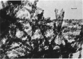
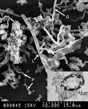 | ||
| Fig. 6 SEM image of mineralized bacteria from the caldera of Axial Vocno resembling the sheath of Leptothrix orchracae (L), Gallionella ferruginea (G) and PV-1 (P). The inset TEM image is a cross-section of a bacterial structure encrusted with nanoparticulate ferrihydrite. Reprinted from ref. 22, Copyright (2004), with permission from Elsevier. | ||
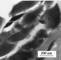
Ferrihydrite aggregates may display smooth textures with very low crystallinity (see Fig. 7). Due to the stabilizing effects of silicates58 and phosphates59 toward ferrihydrite, this smooth texture occurs mostly in silicate- or phosphate-rich environments, and these poorly crystalline ferrihydrites contain high concentrations of Si and P.60 We refer readers to the referenced articles for more information.
 | ||
| Fig. 7 Smooth-textured 2-line ferrihydrite aggregates found in the floodplain at Kohr's Bend, Clark Fork River in Montana, U.S.A. From ref. 61, Copyright (2005), with permission from Mineralogical Society of America. | ||
As mentioned above, ferrihydrite is an important precursor of other more stable phases. Although the morphologies of individual nanoparticles are almost invariant with respect to environmental conditions, their aggregation patterns show large variations and are dependent on the environmental conditions. In morphology-preserving transformations, such as topotacticity, dehydration, and oriented attachment-growth (e.g. with the (0001) direction in common during aggregation), the morphology of aggregated superstructures, rather than that of individual nanoparticles, can be passed on to descendant iron oxides. With this in mind, any species that modifies the aggregation may impact the morphology of iron oxides produced from ferrihydrite.
2.2. Goethite
Goethite (α-FeOOH) is the most common iron oxyhydroxide in soils due to its high thermodynamic stability under ambient conditions.17 Goethite is also common in various aquatic environments with both acidic and alkaline pH. In certain environments (which are enriched with silicate, phosphate, organic matter) nanogoethite was reported to be the dominant precipitated phase,62 but mostly it is transformed from other relatively metastable oxyhydroxides (e.g. ferrihydrite and lepidocrocite) nanoparticles in soils and waters. Since such transformations are typically via dissolution–reprecipitation processes, goethite nanoparticles seldom inherit the morphologies of precursor phases. After the formation of goethite nanoparticles, the dynamic dissolution–reprecipitation process in solution was found to alter the nanomorphology (e.g. aspect ratio of the acicular shapes), and this process could be catalyzed by Fe(II) which is quite common in natural environments.63 The result of the morphology evolution of goethite nanoparticles in solutions is the tendency towards the thermodynamic equilibrium morphology, irrespective of their original morphologies.The morphology of goethite nanoparticles is essentially acicular or needle-like.17 As Fig. 8 shows, the acicular shapes are mainly elongated along the [010] direction (referring to the Pnma setting in the new International Tables for Crystallography64), since the (010) surface has high surface energy and coarsens more rapidly.17 The acicular shapes have closing forms of {101} and {210} at the ends, and when the aspect ratio is very small, goethite needles may be extended and expose their diamond-shaped cross section.17 Such diamond-like shapes (see Fig. 9) were observed in goethite nanoparticles in weathered amphibole (a group of dark rock-forming inosilicate minerals),65 and in acidic (pH ∼ 1.6) solutions in the presence of silicate.66
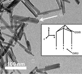 | ||
| Fig. 8 Acicular morphology of goethite nanorods with illustration of enclosing facets in the inset. Adapted with permission from ref. 67. Copyright (2009) American Chemical Society. | ||
 | ||
| Fig. 9 The diamond-like cross sections of goethite nanoparticles. The bar is 50 nm. Reprinted from ref. 66, Copyright (1999), with permission from Elsevier. | ||
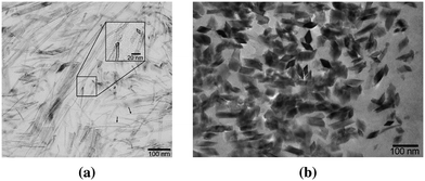
Goethite nanocrystals from soils and sediments may display the usual acicular morphologies, but under poor growth conditions, irregular shapes may predominate, and several distinct morphologies of goethite in soils and sediments have been reported in the literature.17 Fibrous goethite (2–5 nm wide, up to several micrometers long) was found in Japanese and Scottish soils68 and in podzols69 of unidentified origin (see Fig. 10). Goethite nanocrystals in soils may aggregate along specific orientations, indicating oriented-attachment growth from ferrihydrite nanoparticles or fast nucleation on newly formed goethite.21 The aggregations may display a complex tridimensional star shape or a Christmas tree (where each branch also has branches) shape in saprolite soils, and these shapes were produced by multiple twins (see Fig. 11).21 Oriented aggregation may lead to a corn-like shape (Fig. 12), the long axis of which was identified to be the c-axis of goethite.21 Other morphologies include nearly equidimensional shapes associated with large amounts of humic acid in oxisols,70 irregular shapes from an ultisol on basalt, South Brazil, and small acicular shapes from a redoximorphic soil, South Africa.17
 | ||
| Fig. 10 High-resolution TEM picture of unusual fibrous goethite in soils. The bar is 10 nm. Reprinted from ref. 69, Copyright (1984), with permission from Elsevier. | ||
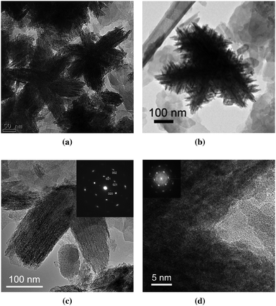 | ||
| Fig. 11 (a) Star-shaped goethite (containing twins); (b) Christmas tree shaped goethite; (c) twinned goethite; (d) HRTEM image of a twin boundary. The (020) reflection is weak or missing in the inset electron diffraction pattern. Reprinted from ref. 21, Copyright (2012), with permission from Pan Stanford Publishing. | ||
 | ||
| Fig. 12 (a) Corn-shaped aggregates of goethite nanocrystals from Rio Tinto, southwest Spain. The goethite coexists of schwertmannite needles. (b) A high-magnification TEM image shows goethite nanocrystals and nanopores among them. (c) HRTEM image showing lattice fringes of neighboring goethite nanocrystals. The (020) reflection is very weak or missing in the inset electron diffraction pattern. Reprinted from ref. 21, Copyright (2012), with permission from Pan Stanford Publishing. | ||
Under solution conditions, goethite nanoparticles may develop equant- to rectangular-platy shapes (up to 10 nm wide and form irregular and dense clusters of 20–30 nm wide, see Fig. 13) in acid mine drainage (pH ∼ 3.7, sulfate concentrations 769–1050 mg L−1).29 These nanogoethites coexisted with schwertmannite, and displayed similarity in the platy morphologies. In alkaline media a pseudohexagonal morphology was observed in the presence of silicates of medium concentrations (10−3 M).58
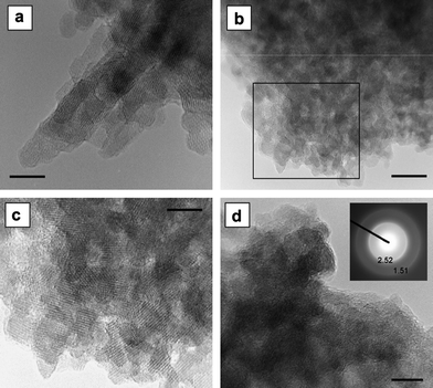 | ||
| Fig. 13 The equant- to rectangular-platy morphology of goethite nanocrystals, and an aggregate of irregular round shaped ferrihydrite nanocrystals for comparison. (a) A multidomain goethite needle with irregular stepped ends (scale bar = 5 nm); (b) an aggregate of equant goethite nanoparticles with platy morphology (scale bar = 20 nm); (c) enlarged view of the marked area in (b) (scale bar = 10 nm); (d) irregular round shaped ferrihydrite aggregate of ferrihydrite nanocrystals (scale bar = 5 nm). In the inset, the SAED pattern with d-values of the two broad rings. Reprinted from ref. 29, Copyright (2012), with permission from Elsevier. | ||
Goethite nanocrystals are found in radular teeth of limpets as a hardening agent.71–75 These biogenic goethite nanocrystals are of the usual acicular shape, ∼20 nm in width and up to 1 μm in length, and their morphologies are highly regulated by the organic matrix, which provides nucleation sites and confines the space for the growth of goethite.17 The presence of ferrihydrite and lepidocrocite (mainly at the base of the radular teeth) indicates the goethite nanocrystals are formed by oxidative precipitation of Fe(II) solution or by rapid transformation from ferrihydrite.75 The formation might not be under strict biological control, like those in magnetosomes for magnetite nanoparticles, as indicated by the diverse sizes and shapes in newly formed goethite nanocrystals (see Fig. 14).74
 | ||
| Fig. 14 Goethite nanocrystals in limpet's radular teeth viewed along (a) side and (b) top. Reprinted with permission from ref. 74. Copyright 2005 American Society of Chemistry. | ||
2.3. Hematite
Bulk hematite is thermodynamically stable under ambient conditions,17 but at the nanoscale, due to its higher surface enthalpies or surface free energies, nanoparticulate hematite combined with water is thermodynamically metastable relative to nanogoethite at small sizes.76–78 This reversal of the relative thermodynamic stability indicates nanoparticulate hematite is usually not the first solid phase formed by precipitation and nucleation, but is a result of transformation from other oxyhydroxide phases. The critical sizes for hematite nanoparticles to be stable decrease with temperature,77,78 so that hematite nanoparticles formed at higher temperatures, such as in high-temperature hydrothermal vents or wild-fire heated soils, can have smaller sizes than those formed at lower temperatures.The free energy of formation of the hematite and H2O combination is very close to that of goethite in the standard state,79 and small variations in the activity of water may alter the order of their relative stability. Fig. 15 shows that hematite nanocrystals form at the edge of goethite, as the weathering dehydration product of goethite under dry conditions. Hematite nanocrystals may also form as oxidation products of eolian magnetite grains or weathering products of Fe-bearing silicate minerals,80 often competing with the other product, maghemite. The relative abundance of hematite/maghemite nanocrystals is dependent on humidity and particulate size, due to the subtle thermodynamic stability of water-passivation on the surfaces.77,81
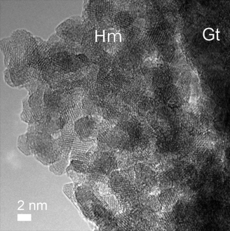 | ||
| Fig. 15 Hematite (highlighted as Hm) nanocrystals at the edge of goethite (Gt) as the weathering dehydration product of goethite under dry conditions. Reprinted from ref. 21, Copyright (2012), with permission from Pan Stanford Publishing. | ||
The morphology of hematite shows large variance and sensitivity to environmental conditions compared to goethite.17 Several reasons are responsible for the diversity of hematite's morphology. The free energies of different surfaces are largely similar,78,82,83 and their relative stability may be readily altered by environmental conditions. Formation routes of hematite also contribute to the diversity of the nanomorphology of hematite. In nature, hematite nanoparticles are mostly formed by dehydration of oxyhydroxides (as from goethite), or combined with aggregation and internal rearrangements (as from ferrihydrite). The formation process is typically related to the reduced chemical activity of water (through decreasing humidity or increasing salinity), or the relief of retarding factors that stabilize those relatively metastable oxyhydroxides. These are essentially solid-state transformations and, therefore, the resultant hematite may inherit the precursor's morphologies. In contrast, goethite nanoparticles are formed from solution through dissolution–reprecipitation processes.
The typical morphologies of hematite (nano)crystals are rounded, rhombohedral and platy.17 The coarsely crystalline morphology mostly exposes the (001) basal plane, and was believed to be associated with high-temperature (>100 °C) processes,23 but oriented aggregation of hematite nanoparticles may also produce this morphology at low temperatures.84 Rounded and rhombohedral morphologies are common in low-temperature environments (see Fig. 16 for an example).
 | ||
| Fig. 16 Hematite nanoparticles found in alkaline soils. Reprinted from ref. 85, Copyright (2007), with permission from Elsevier. | ||
Hematite nanoparticles can form from ferrihydrite by internal rearrangement and dehydration within the ferrihydrite aggregates, preferably at neutral pH and low temperature.86 This formation mechanism led to irregular hexagonal morphologies86 that resembled the aggregation of ferrihydrite nanoparticles. Hematite nanoparticles formed by dehydration of akaganéite and lepidocrocite also maintain the rod- or lath-like morphology of the precursor at high temperatures (<300–400 °C).17 However, hematite nanocrystals formed from goethite in soils showed irregular shapes and random orientations, indicating their formation is not always a simple topotactic transformation.21
2.4. Magnetite and maghemite
Biogenic magnetite nanoparticles have been the subject of a number of recent reviews,87–92 so in the present context we will restrict our discussion to the relationship between the thermochemical conditions and the nanomorphology characteristics of inorganic origin. The typical morphologies of magnetite nanoparticles are octahedral enclosed by {111} planes and rhombo-dodecahedra. Maghemite can form a continuous solid solution with magnetite, and is usually formed by solid state transformation from another iron oxide or iron compound and almost always adopts the morphology of its precursor materials.17Fig. 17 shows maghemite nanoparticles of cuboctahedral shapes in the Chinese Loess sediments, supposedly transformed from biogenic magnetite nanoparticles.21,81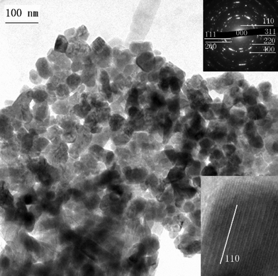 | ||
| Fig. 17 Maghemite nanoparticles showing elongated cuboctahedral morphologies from the Loess. Reprinted from ref. 21, Copyright (2012), with permission from Pan Stanford Publishing. | ||
Magnetite nanoparticles are common reduction products of ferric oxyhydroxides in anoxic sediments and soils.93 Their formation typically involves biomineralisation by iron-reducing bacteria which gain energy through oxidisation of organic matter using nitrate and Fe(III). Magnetite forms by coprecipitation reactions that, as shown in analogous synthesis experiments,94 follow a number of different pathways but the predominant process is a topotactic transformation of goethite to magnetite. In aerated environments magnetite is unstable and is subject to weather, and maghemite is a main weathering product of magnetite. Maghemite nanoparticles in soils can also form through dehydration of lepidocrocite nanoparticles.95 Maghemite is metastable relative to hematite, but nanomaghemite is more stable than nanohematite, especially under dry conditions,77,81 and therefore occurs in the local dry environment of the Chinese Plateau.21,81
Thermolysis experiments at 300 °C indicate that the size and morphology of secondary magnetite particles are influenced by the precursor siderite, and suggest that abiotic magnetite microcrystals or nanoparticles with elongated or other uncommon morphologies may potentially inherit the antecedent morphologies of Fe-carbonate-bearing minerals.96
In confined space and over a long time of equilibration (such as in the pores of meteorites), magnetite nanoparticles’ shapes seemed to be correlated with their sizes, and seemed to be determined by the patterns formed when they aggregate.97
The magnetite crystals in Martian meteorite ALH84001 were found to share some features with those in magnetotactic bacteria MV-1, including single-domain size, chemical purity, and crystallographic perfection. The unusual hexaoctahedral geometry, and elongation along the [111] axis, fueled speculation that the Martian magnetite nanoparticles were biogenic, and were used as evidence of life in the early Martian environment.98 The authors found that the truncated hexa-octahedral magnetites in ALH84001 have no known terrestrial abiotic analog.99 However, Buseck et al.100 found that the nanomorphology of magnetite nanocrystals from ALH84001, using tomographic and holographic methods, differs from those in bacterial strains, leading to doubt as to whether the crystallographic and morphological evidence were adequate to infer their origin. Furthermore, Golden et al. proposed that the magnetites from ALH84001 are exclusively inorganic, with evidence that thermal decomposition can produce magnetites of similar morphology, and this synthesis process is consistent with the environment and history of the Martian meteorite.101 Other viewpoints are in between the above two. Gibson et al.102 pointed out the possibility of contamination of the meteorites, and even questioned whether or not the meteorites are Martian.
Based on the persistence of specific nanomorphologies of magnetite, and their thermochemical conditions, Arató proposed that the size and shape distributions of magnetite nanocrystals can serve as a potential biomarker to discriminate inorganic or biogenic origins.103 They found that biogenic magnetite nanocrystals have an asymmetric and negatively skewed size distribution, which is distinctly different from synthetic nanoparticles. Faivre and Zuddas104 proposed combining oxygen isotope fractionation and crystal size distributions to discriminate magnetites of abiotic or biotic, inorganic or intracellular origins. Kopp and Kirschvink further proposed a scoring scheme that weighs all these aspects to assess the origins of magnetite nanoparticles.105
2.5. Lepidocrocite, akaganéite and schwertmannite
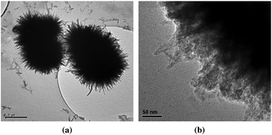
This final group of oxyhydroxide phases are thermodynamically metastable relative to goethite under ambient conditions. Each phase displays characteristic morphologies: lepidocrocite nanocrystals are lath-like or tabular, exposing mainly (010) surfaces, akaganéite nanocrystals are lath-like and aggregate into spindles or rods elongated along the [001] direction (see Fig. 18), and schwertmannite forms into perfectly spherical, hedgehog-like, or pin-cushion aggregates that consist of radially oriented, filamentous nanocrystals (see Fig. 19).17 | ||
| Fig. 18 Laths of (a) lepidocrocite and (b) akaganéite found respectively in saline sand-bed waterways in Hunter Valley, Australia, and in the microbial mats in a closed Pb–Zn mine in Wisconsin, U.S.A. Subfigure (a) is reprinted from ref. 24, and (b) from ref. 27, both Copyright (2009), with permissions from Elsevier. | ||
 | ||
| Fig. 19 Typical morphology of schwertmannite aggregates (a) and nanoparticles consisting of the whiskers (b). Reprinted from ref. 28, Copyright (2005), with permission from Elsevier. | ||
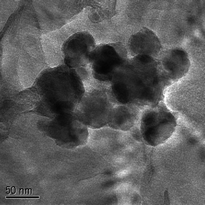
Forming in chloride- or fluoride-rich environments, such as oceans, mines, groundwater, saline lakes, hot brines, acidic soils, and volcanoes,17,25 akaganéite is always associated with chloride or fluoride ions, which reside in channels surrounded by Fe–O/OH octahedra. All natural akaganéite are nanosized particles. Schwertmannite is the dominant mineral forming at acidic pH (3–4.5) and high sulfate concentrations (1000–3000 mg L−1).26 At lower pH and higher sulfate concentrations, jarosite precipitates, while at higher pH and lower sulfate concentrations ferrihydrite nanoparticles form, especially in the presence of high organic carbon contents.106
In acid mine drainage waters, the usual schwertmannite pin-cushions consisted of multi-domain whiskers up to 50–60 nm in length and 2–4 nm in width (see Fig. 19(b)), and these nanocrystals might gradually develop goethite with similar morphologies.29 Morphologically the schwertmannite nanocrystals resemble those of ferrihydrite, and it was proposed that schwertmannite is an intermediate phase in the ferrihydrite crystallization series, with its formation specially governed by supersaturation of Fe(III).28 Absorbed As could stabilize schwertmannite by inhibiting nucleation of goethite, but did not modify the morphology of schwertmannite.30
In strongly acidic solutions (pH < 3.5), precipitation of schwertmannite is usually mediated by acidophilic iron-oxidizing bacteria, including Acidithiobacillus ferrooxidans,31,32 and Ferrovum myxofaciens.107–109 The bacteria-mediated products were found to depend on pH: at higher pH (= 3.51) natrojarosite may form, while at lower pH (1.60–3.44) the product is exclusively schwertmannite.32 Photocatalysis of natural sphalerite may also influence the biomineralization of schwertmannite (and jarosite).110 In the presence of ammonium, jarosite instead of schwertmannite seemed to be the stable biomineralization product at pH = 2.
The biomineralization by Acidithiobacillus ferrooxidans can also produce akaganéite, but if both sulfate and chloride are present, the biomineralization product was found to be schwertmannite only, indicating sulfate inhibits drastically the formation of akaganéite.111 The presence of chlorides seemed to decrease the aggregation size of the newly formed schwertmannite.
All these oxyhydroxide phases (including ferrihydrite) are metastable relative to goethite under ambient conditions. Goethite may form (from ferrihydrite) in a large pH range,86 but the phase transformation rate varies largely depending on the environmental conditions. It was found that the stability of these oxyhydroxides is governed by solution conditions (pH, Eh, temperature, activities of Fe(III), Fe(II) and various foreign species) and kinetic factors (mixing or neutralizing rate).29,106,112–121
3. Thermodynamic stability
The thermodynamic stability of nanomaterials is increasingly governed by surface interactions with decreasing particle size, because of the disproportion of large surface areas, and distinct chemical and physical properties at the nanoscale.33,77,122–124 The well established relative stability of bulk materials is not extendable to nanomaterials, and crossovers in polymorph stability have frequently been observed when the sizes are decreased to the nanoscale.122 This is especially obvious in iron oxides and oxyhydroxides because the differences in free energies between stable and metastable phases are very small (a few kJ mol−1),123 being readily overridden by contributions from surfaces. Therefore, metastable iron oxides and oxyhydroxides are often kinetically accessible when precipitated from aqueous solution, and are further stabilized as small particles via various mechanisms.77 A refreshed understanding of the thermodynamic stability of iron oxide nanostructures is thus necessary given their geochemical, biological and technological significance. Accurate experimental measurement and computational modeling of surface and interface properties are indispensable for this purpose. High-level morphology models can be built with these data to bring forth a map linking formation conditions and nanostructures and properties. These are the subjects of this and the next sections.Iron oxide nanostructures are mostly passivated by water molecules (via physisorption) and hydroxyl groups (via chemisorption) in aquatic and most terrestrial environments. The thermodynamics of iron oxide nanostructures are therefore dependent on the extent of surface hydration, in addition to their bulk polymorphs and particle size (or surface area).77 Surface hydration, in turn, is dependent on the activity of water and environmental conditions. This has posed difficulty in structural characterization of surfaces and calorimetric measurements of these nanoparticles, because of difficulties in maintaining the hydrous environmental conditions during characterization and measurements, often in high vacuum and with high-energy beam damage. Structural characterization of hydrated surfaces has been demonstrated in the crystal truncation rod diffraction method,125 which in theory can measure the amount of adsorbed water. Advances have also been made in calorimetric measurements of hydrated surfaces by coupling a microcalorimeter to a gas-adsorption analytical system which, in combination, simultaneously measures the adsorption enthalpies of water and the amount of adsorbed water.126 This also involves solution calorimetry of well characterized samples of different polymorphs (with known surface area and water content).76,127–129
Using hydration-capable calorimetric techniques (e.g. acid-solution calorimetry76 and water-adsorption calorimetry128), it has been shown that the phase stability of iron oxide nanostructures is very different under hydrous and anhydrous conditions (see Fig. 20). Crossovers are common with decreasing particle size or increasing surface area. Among the hydrated nanostructures, goethite is thermodynamically stable for a large range of surface areas, intersecting only with hematite (combined with water) when the surface area is close to zero, and ferrihydrite, akaganéite and lepidocrocite at the nanoscale (large surface area). This is in accordance with experimental observations that goethite is usually a final product of phase transformations in waters, soils, and humid air. However, as the free energy differences are very small between goethite and other metastable oxyhydroxides at the nanoscale, all the phases have a probability of nucleating and precipitating from supersaturated solutions. By extrapolating the lines of the formation enthalpies in Fig. 20 to even larger surface area (or smaller particle size), one finds that the metastable oxyhydroxide phases become more stable than nanogoethite (in the absence of hydration), and therefore should preferably form rather than goethite. This is in agreement with the above-mentioned Ostwald's rule.
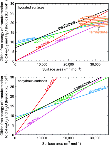 | ||
| Fig. 20 Enthalpy, relative to bulk hematite combined with liquid water at 298 K, of various iron oxide and oxyhydroxide polymorphs as a function of surface area per mole of FeO, FeOOH, or Fe(OH). Values for ferrihydrite are approximate because of sample variability and are represented as an elliptical area. Values of surface areas are plotted for formula units FeOOH (oxyhydroxides), Fe(OH) (ferrihydrite), and FeO (hematite and maghemite) for thermodynamic consistency when comparing different compositions. From ref. 77, Copyright (2008); reprinted with permission from AAAS. | ||
As shown in Fig. 20, hematite has very different size-dependence under hydrous and anhydrous conditions. Under hydrous conditions, the surface enthalpy of hematite nanoparticles is similar to other phases, indicating the surface bonding for water on all these phases is similar. Under anhydrous conditions, since the binding strength of water on hematite surfaces decreases with decreasing particle size,77 hematite nanoparticles become less passivated by water compared to coarse hematite, and have much higher formation energies compared to other phases. Maghemite seems to hold water tightly even under anhydrous conditions, therefore remains similar in formation energy compared with the oxyhydroxide phases.
In addition to size or surface area, other environmental conditions, such as temperature and humidity also affect the thermodynamic stability of the phases at the nanoscale. As shown in Fig. 21, higher temperatures are required for the formation of hematite nanoparticles of smaller size,130–132 because the passivation effects of water decrease with particulate size. The relative abundance of goethite and hematite was shown to be related to water's activity in solution and humid air.133
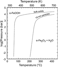 | ||
| Fig. 21 Pressure–temperature diagram for the reaction α-FeOOH (goethite) = α-Fe2O3 (hematite) + H2O (fluid). The curve at lower temperature shows the equilibrium among bulk solid phases and water (fluid implies liquid, vapour, or fluid above the critical ice point), whereas that at higher temperature shows the equilibrium for 10 nm particles of goethite and hematite combined with water. From ref. 77, Copyright (2008); reprinted with permission from AAAS. | ||
The formation of solid oxide and oxyhydroxide phases from ferrihydrite was found to be sensitive to environmental conditions, such as the activity of water, temperature, pH, redox potential, and various ions. Goethite and hematite are two competing phases, with goethite predominating at high humidity (close to 100%) and at cool temperatures while hematite predominates at reduced humidity and elevated temperatures.133 In aqueous suspensions (where the activity of water is close to that of pure water) alkaline (pH = 12) or acid (pH = 4) conditions are preferable for goethite formation, while neutral pH (between 7 and 8) is preferable for hematite formation.86 Silicates and phosphates generally inhibit the transformation of ferrihydrite.58,134 As a result, natural samples of goethite and hematite found in sediments contain low concentrations of Si, while the Si–Fe ratio in ferrihydrite may vary between 0.17 and 0.89.135 It was found that Ca concentration also affects the nucleation and growth of competing hematite and goethite from ferrihydrite: with a low concentration of Ca (up to 2.25%), acicular goethite particles were the major product; and with high concentration (>2.25%), pseudocubic hematite particles are formed.136
It was found that the reductive dissolution of iron oxides trapped in ice grain boundaries could be accelerated by illumination, therefore producing Fe(II) when the ice gets thawed.137 The enhanced photogeneration of Fe(II) in ice was confirmed regardless of the type of iron oxides (hematite, maghemite, or goethite) and the kind of electron donors (mostly organic matter).
The transformations from ferrihydrite to more crystalline phases can be catalyzed by Fe(II) ions, which facilitate dissolution and electrochemical reactions where there are potential gradients. This catalytic effect may also be expressed when reductive species are added to the system to generate Fe(II), such as ZnS.138
Natural iron oxide nanoparticles typically have characteristic shapes. This reflects the importance of morphology in determining the thermodynamic stability of the nanophase iron oxides and oxyhydroxides. However, because difficulties intervene with precise characterization of particle shapes and enclosing facets, morphology was rarely considered in previous calorimetric measurements,77 even though there are multidisciplinary interests in producing nanoparticles with specific shapes to optimise their magnetic and electronic properties. In this process, predictive morphology modelling, as will be presented in the next section, is very useful to provide guidance to synthesis of nanoparticles.
4. Morphology modelling
Although the materials chemistry of naturally occurring iron oxides and oxyhydroxides is complex, it is reasonably well defined (as described above), and (with the obvious exception of ferrihydrite) the resultant structures can typically be well characterized using existing techniques (such as X-ray diffraction, neutron diffraction, electron microscopy). This represents an ideal topic of theory and simulation, which can complement experimental observations by delving more deeply into specific issues or conducting virtual experiments under specific conditions.139 With computation, the environmental conditions and surface structures can be precisely controlled, while experiments may experience reproducibility problems. Specific aspects, such as the electronic structures, morphologies, and interfaces, of the nanostructures can be examined in detail to enable deep understanding of their materials chemistry.Computational modeling has accompanied experimental studies of synthetic iron oxides since the late 1980s and early 1990s.82,140,141 These early collaborations were restricted to classical simulation methods based on interatomic potentials, with no description of electronic properties or incorporation of electron correlation, but did report the relative stability of different surface orientations in reasonable agreement with the facets observed on different samples. These simulation results were typically combined to predict the shapes of individual nanoparticles, and compared with those synthesized in experiments. Since this time, others have built upon this idea, with increasing levels of computational sophistication and the application of more advanced nanomorphological models.
Significant progress has recently been made in morphological modelling, which allows for adequate complexity to incorporate phases, shapes and sizes, and ideally to include environmental conditions through surface stabilities.142 The complete derivation of this model includes contributions from surfaces, edges, corners and planar defects (such as twins and stacking faults),143 and the validity has been tested with metals,144–148 sulphides,149–156 and oxide157–160 nanoparticles.
This model has been applied to iron oxide and oxyhydroxide nanoparticles, and the shape and phase stability was predicted as a function of size.78 In this particular study, the relationship between size, shape, and thermodynamic stability of unpassivated hematite and goethite nanoparticles was investigated, based on reliable first principles calculations and thermochemical data extracted from the JANAF Thermochemical Tables,161 which were incorporated using established ab initio thermodynamics techniques,162 to introduce the pressure and temperature dependence of the system.
In the absence of surface passivation, this combination also predicted the relative surface stability of hematite and goethite, but extended the results to predict the relative stability of different particle shapes as a function of size and temperature. The results demonstrated that the phase transformation from goethite to hematite is highly dependent on both of these parameters, with goethite nanoparticles being thermodynamically stable with small size (compared to hematite, water combination), and the equilibrium transformation temperature increasing rapidly as the particle size decreases (see Fig. 22). As we can see, this is in agreement with the thermochemical analysis of hydrated iron oxides of Navrotsky et al.(above),77 even in the absence of explicit surface hydration.
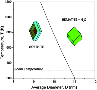 | ||
| Fig. 22 Size- and temperature-dependent thermodynamic stability of goethite and hematite nanoparticles in the presence of water. Reprinted from ref. 78. | ||
More recently, the same approach has been used to introduce more chemical complexity into this sort of prediction, by studying the various types of surface passivations that may arise when the surfaces of iron oxide nanoparticles are exposed to water. This has begun with the development of detailed surface phase diagrams163,164 which map the surface chemistry to the surrounding conditions, as a function of temperature or the partial pressure of oxygen and/or water. By completing this analysis for all relevant facets of hematite, goethite and magnetite it will be possible to extend the environmentally dependent bulk phase diagram165 to include nanoparticles (as a function of size), as it will include the important relationship between the surfaces and the surroundings under different conditions. One could also use the same approach to model the influence of silicates, phosphates, organic matter, or acidity, in addition to humidity and oxygen or iron supersaturation.
However, although nanomorphology models are exceptionally good at dealing with spanning size scales and large multi-dimensional parameter spaces, they fail to capture the dynamical processes in the regions close to the nanoparticles. To this end, Spagnoli et al.166 used classical molecular dynamics simulations to investigate the effects of particle size and morphology on the time-averaged structure and the dynamics of water molecules around 1.6 nm and 2.7 nm hematite nanoparticles. Rather than showing how the nanoparticle morphology and stability responds to the presence of water (as above), this study was particularly useful in showing how the structure of the surrounding water responds to the presence of the nanoparticles. The authors found that ordering of the water molecules occurred in regions close to the nanoparticle surface (irrespective of particle size), but the extent of localization was sensitive to nanoparticle size and morphology. In addition to this, the connectivity between regions of ‘bound water’, and the rates of molecular exchange between inner and outer regions also depended on the hematite nanomorphology, which are related to the rates of interfacial processes and the transport of aqueous ions to surface sites. An example of the atomic density maps, and radial distribution functions used to illustrate the results is provided in Fig. 23.
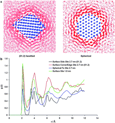 | ||
| Fig. 23 Cross section of water density around a 2.7 nm (012) faceted and spherical particle. The blue color indicates an iron site, pink color indicates the area with low water density and red color indicates the area with high water density. (b) Partial radial distribution function of an iron site on a planar surface (black line) and corner/edge surface site (red line) of a 2.7 nm (012) particle, an iron site on a spherical surface (blue line) and an iron site on a 1.6 nm disordered particle (green line) with the oxygen of the water molecules. Reprinted from ref. 166, Copyright (2009), with permission from Elsevier. | ||
5. Remarks
The iron oxide and oxyhydroxide nanostructures have special significance for ecosystems. In terms of surface adsorption, ferrihydrite and other oxyhydroxide nanoparticles that possess large surface area to volume ratio are particularly useful. The adsorption capacity is closely related to morphology and crystallinity. Increases in crystallinity of ferrihydrite or the formation of more crystalline phases (such as goethite or hematite) cause significant decrease in adsorbed As and U contents.8–10 In this case, it is desirable to maintain environmental conditions under which these poorly crystalline phases are stabilized to maximize the heavy-metal sequestration in contaminated waters and soils.The iron oxide phases in natural environmental settings carry information about the physical and chemical conditions of their formation and storage environments. For example, finely grained hematite particles found in Mars’ surface soils may indicate the existence of water during their formation,167,168 and coexistence of hematite with jarosite indicated Mars’ surface water evaporated in a very short period of time.169,170 The retention of schwertmannite nanoparticles in icebergs171 implied that liquid-like ice grain boundaries can be strongly acidic.
Iron oxide and oxyhydroxide nanoparticles typically display their characteristic morphologies which appear to be insensitive to environmental conditions. However, there are three aspects in which the surrounding chemistry plays an important role in determining the nanomorphologies. First, the nanostructures may bear the morphologies of their precursors in topotactic transformations, which are determined by environmental conditions. It is straightforward to make hematite nanorods from goethite nanorods, and maghemite nanolaths from lepidocrocite nanolaths through dehydration. The phase-dependent morphology modeling (Section 4) will provide guidance for the size- and shape-dependent phase transformations. Secondly, the aggregation patterns, which are sensitive to environmental conditions, can produce superstructures with distinct morphologies. New phases can form by internal rearrangement, dehydration, and intergrowth from these superstructures. Oriented aggregations are common in iron oxide and oxyhydroxide nanoparticles, probably due to interparticle magnetic interactions. This way may generate both solid and hollow nanostructures, as well as nanopores. Thirdly, the environmental conditions affect the activity of microbes, and indirectly affect the products and morphologies of nanophases in their biological activities. It has been demonstrated that environmental conditions affect the morphologies of magnetite nanoparticles produced by magnetotactic bacteria.172 These can be applied in the synthesis of iron oxide and oxyhydroxide nanoparticles to optimize their morphologies for specific applications.
Acknowledgements
This project has been supported by the Australian Research Council under grant number DP0986752.References
- J. F. Banfield and H. Zhang, Rev. Mineral. Geochem., 2001, 44, 1–58 CrossRef CAS
.
- M. F. Hochella, Jr, Elements, 2008, 4, 373–379 CrossRef
-
Nature's Nanostructures, ed. A. S. Barnard and H. Guo, Pan Stanford Publishing, Singapore, 2012 Search PubMed
- J. L. Jambor and J. E. Dutrizac, Chem. Rev., 1998, 98, 2549–2585 CrossRef CAS
- J. K. Moore, S. C. Doney, D. M. Glover and I. Y. Fung, Deep-Sea Res., Part II, 2002, 49, 463–507 CrossRef CAS
- A. C. Maloof, R. E. Kopp, J. P. Grotzinger, D. A. Fike, T. Bosak, H. Vali, P. M. Poussart, B. P. Weiss and J. L. Kirschvink, Earth Planet. Sci. Lett., 2007, 259, 581–598 CrossRef CAS
-
M. F. Hochella, Jr, D. Aruguete, B. Kim and A. S. Madden, Nature's Nanostructures, Pan Stanford Publishing, Singapore, 2012, ch. 1, pp. 1–42 Search PubMed
- J. Gautier, C. Grosbois, A. Courtin-Nomade, J. P. Floc'h and F. Martin, Eur. J. Mineral., 2006, 18, 187–195 CrossRef CAS
- W. R. Richmond, M. Loan, J. Morton and G. M. Parkinson, Environ. Sci. Technol., 2004, 38, 2368–2372 CrossRef CAS
- T. E. Payne, J. A. Davis and D. T. Waite, Radiochim. Acta, 1994, 66/67, 297–303 CAS
- S. Bose, M. F. Hochella, Jr, Y. A. Gorby, D. W. Kennedy, D. E. McCready, A. S. Madden and B. H. Lower, Geochim. Cosmochim. Acta, 2009, 73, 962–976 CrossRef CAS
- R. Raiswell, Deep-Sea Res., Part II, 2011, 58, 1364–1375 CrossRef CAS
- T. J. Shaw, R. W. Raiswell, C. R. Hexel, H. P. Vu, W. S. Moore, R. Dudgeon and K. L. Smith, Jr, Deep-Sea Res., Part II, 2011, 58, 1376–1383 CrossRef CAS
- D. P. Connelly, J. T. Copley, B. J. Murton, K. Stansfield, P. A. Tyler, C. R. German, C. L. Van Dover, D. Amon, M. Furlong, N. Grindlay, N. Hayman, V. Hühnerbach, M. Judge, T. Le Bas, S. McPhail, A. Meier, K. Nakamura, V. Nye, M. Pebody, R. B. Pedersen, S. Plouviez, C. Sands, R. C. Searle, P. Stevenson, S. Taws and S. Wilcox, Nat. Commun., 2012, 3, 620 CrossRef
- K. M. Haase, S. Petersen, A. Koschinsky, R. Seifert, C. W. Devey, R. Keir, K. S. Lackschewitz, B. Melchert, M. Perner, O. Schmale, J. Süling, N. Dubilier, F. Zielinski, S. Fretzdorff, D. Garbe-Schönberg, U. Westernströer, C. R. German, T. M. Shank, D. Yoerger, O. Giere, J. Kuever, H. Marbler, J. Mawick, C. Mertens, U. Stöber, M. Walter, C. Ostertag-Henning, H. Paulick, M. Peters, H. Strauss, S. Sander, J. Stecher, M. Warmuth and S. Weber, Geochem., Geophys., Geosyst., 2007, 8, Q11002 CrossRef
- D. K. Nordstrom, C. N. Alpers, C. J. Ptacek and D. W. Blowes, Environ. Sci. Technol., 2000, 34, 254–258 CrossRef CAS
-
R. M. Cornell and U. Schwertmann, The Iron Oxides, Wiley-VCH, Weinheim, Germany, 2nd edn, 2003 Search PubMed
- P. Nørnberg, A. L. Vendelboe, H. P. Gunnlaugsson, J. P. Merrison, K. Finster and S. K. Jensen, Clay Miner., 2009, 44, 239–247 CrossRef
- A. S. Teja and P.-Y. Koh, Prog. Cryst. Growth Charact. Mater., 2009, 55, 22–45 CrossRef CAS
- D. A. Wheeler, G. Wang, Y. Ling, Y. Li and J. Z. Zhang, Energy Environ. Sci., 2012, 5, 6682–6702 CAS
-
H. Konishi, H. F. Xu and H. Guo, Nature's Nanostructures, Pan Stanford Publishing, Singapore, 2012, ch. 3, pp. 75–113 Search PubMed
- C. B. Kennedy, S. D. Scott and F. G. Ferris, Chem. Geol., 2004, 212, 269–277 CrossRef CAS
- D. C. Catling and J. M. Moore, Icarus, 2003, 165, 277–300 CrossRef CAS
- L. S. Isaacson, E. D. Burton, R. t. Bush, D. R. G. Mitchell, S. G. Johnston, B. C. T. Macdonald, L. A. Sullivan and I. White, Appl. Geochem., 2009, 24, 1825–1834 CrossRef CAS
- I. Bibi, B. Singh and E. Silvester, Geochim. Cosmochim. Acta, 2011, 75, 6429–6438 CrossRef CAS
- J. M. Bigham, L. Carlson and E. Murad, Mineral. Mag., 1994, 58, 641–648 CAS
- C. S. Chan, S. C. Fakra, D. C. Edwards, D. Emerson and J. F. Banfield, Geochim. Cosmochim. Acta, 2009, 73, 3807–3818 CrossRef CAS
- M. Loan, W. R. Richmond and G. M. Parkinson, J. Cryst. Growth, 2005, 275, e1875–e1881 CrossRef CAS
- P. Marescotti, C. Carbone, P. Comodi, F. Frondini and G. Lucchetti, Appl. Geochem., 2012, 27, 577–589 CrossRef CAS
- S. Paikaray and S. Peiffer, Appl. Geochem., 2012, 27, 590–597 CrossRef CAS
- Z. Long, Y. Huang, Z. Cai, W. Cong and F. Ouyang, Biotechnol. Lett., 2003, 25, 245–249 CrossRef CAS
- Y. Liao, L. Zhou, J. Liang and H. Xiong, Mater. Sci. Eng., C, 2009, 29, 211–215 CrossRef CAS
- M. F. Hochella, Jr, S. K. Lower, P. A. Maurice, R. L. Penn, N. Sahai, D. L. Sparks and B. S. Twining, Science, 2008, 319, 1631–1635 CrossRef
- M. Fleischer, G. Y. Chao and A. Kato, Am. Mineral., 1975, 60, 485–489 Search PubMed
- R. A. Eggleton and R. Fitzpatrick, Clays Clay Miner., 1988, 36, 111–124 CAS
- J. Zhao, F. E. Huggins, Z. Feng and G. P. Huffman, Clays Clay Miner., 1994, 42, 737–746 CAS
- B. A. Rea, J. A. Davis and G. A. Waychunas, Clays Clay Miner., 1994, 42, 23–34 CAS
- B. L. Poulson, C. M. Johnson and B. L. Beard, Am. Mineral., 2005, 90, 758–763 CrossRef
- A. Manceau, J. M. Combes, G. Calas, R. A. Eggleton and R. W. Fitzpatrick, Clays Clay Miner., 1990, 38, 331–336 CAS
- D. Carta, M. F. Casula, A. Corrias, A. Falqui, G. Navarra and G. Pinna, Mater. Chem. Phys., 2009, 113, 349–355 CrossRef CAS
- N. Pinney, J. D. Kubicki, D. S. Middlemiss, C. P. Grey and D. Morgan, Chem. Mater., 2009, 21, 5727–5742 CrossRef CAS
- T. Hiemstra and W. H. van Riemsdijk, Geochim. Cosmochim. Acta, 2009, 73, 4423–4436 CrossRef CAS
- F. M. Michel, S. M. Antao, P. L. Lee, P. J. Chupas, G. Liu, D. R. Strongin, M. A. A. Schoonen, B. L. Phillips and J. B. Parise, Science, 2007, 316, 1726–1729 CrossRef CAS
- D. G. Rancourt and J.-F. Meunier, Am. Mineral., 2008, 93, 1412–1417 CrossRef CAS
- A. Manceau, Clay Miner., 2009, 44, 19–34 CrossRef CAS
- F. M. Michel, V. Barrón, J. Torrent, M. P. Morales, C. J. Serna, J. F. Boily, Q. Liu, A. Ambrosini, A. C. Cismasu and G. E. Brown, Jr, Proc. Natl. Acad. Sci. U. S. A., 2010, 107, 2787–2792 CrossRef CAS
- A. Manceau, Clay Miner., 2010, 45, 225–228 CrossRef CAS
- A. Gloter, M. Zbinden, F. Guyot, F. Gaill and C. Colliex, Earth Planet. Sci. Lett., 2004, 222, 947–957 CrossRef CAS
- A. J. Frierdich, E. A. Hasenmueller and J. G. Catalano, Chem. Geol., 2011, 284, 82–96 CrossRef CAS
- S. Glasauer, S. Langley and T. J. Beveridge, Appl. Environ. Microbiol., 2001, 67, 5544–5550 CrossRef CAS
- T. Threlfall, Org. Process Res. Dev., 2003, 7, 1017–1027 CrossRef CAS
- J. F. Banfield, S. A. Welch, H. Z. Zhang, T. T. Ebert and R. L. Penn, Science, 2000, 289, 751–754 CrossRef CAS
- R. Matthies, A. C. Aplin, B. R. Horrocks and L. K. Mudashiru, J. Environ. Monit., 2012, 14, 1174 RSC
- K. Eusterhues, F. E. Wagner, W. Hausler, M. Hanzlik, H. Knicker, K. U. Totsche, I. Kogel-Knabner and U. Schwertmann, Environ. Sci. Technol., 2008, 42, 7891–7897 CrossRef CAS
- K. L. Straub, M. Hanzlik and B. E. E. Buchholz-Cleven, Syst. Appl. Microbiol., 1998, 21, 442–449 CrossRef CAS
- K. L. Straub and B. Schink, Arch. Microbiol., 2004, 182, 175–181 CrossRef CAS
- C. B. Kennedy, S. D. Scott and F. G. Ferris, Geomicrobiol. J., 2003, 20, 199–214 CrossRef CAS
- R. M. Cornell, R. Giovanoli and P. W. Schindler, Clays Clay Miner., 1987, 35, 21–28 CAS
- N. Gálvez, V. Barrón and J. Torrent, Clays Clay Miner., 1999, 47, 304–311 Search PubMed
- R. Kaegi, A. Voegelin, D. Folini and S. J. Hug, Geochim. Cosmochim. Acta, 2010, 74, 5798–5816 CrossRef CAS
- M. F. Hochella, Jr, T. Kasama, A. Putnis, C. V. Putnis and J. N. Moore, Am. Mineral., 2005, 90, 718–724 CrossRef
- C. van der Zee, D. R. Roberts, D. G. Rancourt and C. P. Slomp, Geology, 2003, 31, 993–996 CrossRef CAS
- R. M. Handler, B. L. Beard, C. M. Johnson and M. M. Scherer, Environ. Sci. Technol., 2009, 43, 1102–1107 CrossRef CAS
-
International Tables for Crystallography, ed. T. Nahn, Springer, 5th edn, 2005, vol. A, space-group symmetry, corrected reprint Search PubMed
- K. L. Smith and R. A. Eggleston, Clays Clay Miner., 1983, 31, 392–396 CAS
- S. M. Glasauer, J. Friedl and U. Schwertmann, J. Colloid Interface Sci., 1999, 216, 106–115 CrossRef CAS
- D. M. Cwiertny, G. J. Hunter, J. M. pettibone, M. M. Scherer and V. H. Grassian, J. Phys. Chem. C, 2009, 113, 2175–2186 CAS
- M. Nakai and N. Yoshinada, Geoderma, 1980, 24, 143–158 CrossRef CAS
- A. W. Fordham, R. H. Merry and K. Norrish, Geoderma, 1984, 34, 135–148 CrossRef CAS
- M. R. Fontes, S. B. Weed and L. H. Bowen, Soil Sci. Soc. Am. J., 1992, 56, 982–990 CrossRef CAS
- H. A. Lowenstam, Science, 1962, 137, 279–280 CAS
- S. Mann, C. C. Perry, J. Webb, B. Luke and R. J. P. Williams, Proc. R. Soc. London, Ser. B, 1986, 227, 179–190 CrossRef CAS
- P. van der Wal, J. Ultrastruct. Mol. Struct. Res., 1989, 102, 147–161 CrossRef
- E. D. Sone, S. Weiner and L. Addadi, Cryst. Growth Des., 2005, 5, 2131–2138 CAS
- R. M. Cornell and W. Schneider, Polyhedron, 1989, 8, 149–155 CrossRef CAS
- L. Mazeina and A. Navrotsky, Clays Clay Miner., 2005, 53, 113–122 CrossRef CAS
- A. Navrotsky, L. Mazeina and J. Majzlan, Science, 2008, 319, 1635–1638 CrossRef CAS
- H. Guo and A. S. Barnard, J. Mater. Chem., 2011, 21, 11566–11577 RSC
- J. Majzlan, K.-D. Grevel and A. Navrotsky, Am. Mineral., 2003, 88, 855–859 CAS
- T. Chen, Q. Xie, H. Xu, J. Chen, J. Ji, H. Lu and W. Balsam, Catena, 2010, 81, 217–225 CrossRef CAS
- T. Chen, H. Xu, Q. Xie, J. Chen, J. Ji and H. Lu, Earth Planet. Sci. Lett., 2005, 240, 790–802 CrossRef CAS
- N. J. Reeves and S. Mann, J. Chem. Soc., Faraday Trans., 1991, 87, 3875–3880 RSC
- P. Hartman, J. Cryst. Growth, 1989, 96, 667–672 CrossRef CAS
- A. S. Madden, V. E. Hamilton, M. E. E. Madden, P. R. Larson and M. A. Miller, Earth Planet. Sci. Lett., 2010, 298, 377–384 CrossRef CAS
- N. P. Qafoku, O. Qafoku, C. C. Ainsworth, A. Dohnalkova and S. G. McKinley, Appl. Geochem., 2007, 22, 2054–2064 CrossRef CAS
- U. Schwertmann and E. Murad, Clays Clay Miner., 1983, 31, 277–284 CAS
- D. Fortin and S. Langley, Earth-Sci. Rev., 2005, 72, 1–19 CrossRef CAS
- C. Lang and D. Schüler, J. Phys.: Condens. Matter, 2006, 18, S2815–S2828 CrossRef CAS
- D. A. Bazylinski and D. Schüler, Adv. Appl. Microbiol., 2007, 62, 21–62 CrossRef CAS
- A. Arakaki, H. Nakazawa, M. Nemoto, T. Mori and T. Matsunaga, J. R. Soc. Interface, 2008, 5, 977–999 CrossRef CAS
- A. Fischer, M. Schmitz, B. Aichmayer, P. Fratzl and D. Faivre, J. R. Soc. Interface, 2011, 8, 1011–1018 CrossRef CAS
-
A. Körnig and D. Faivre, Nature's Nanostructures, Pan Stanford Publishing, Singapore, 2012, ch. 9, pp. 249–271 Search PubMed
- D. E. Cummings, A. W. March, B. Bostick, S. Spring, F. Caccavo, Jr., S. Fendorf and R. F. Rosenzweig, Appl. Environ. Microbiol., 2000, 66, 154–162 CrossRef CAS
- T. Ahn, J. H. Kim, H.-M. Yang, J. W. Lee and J.-D. Kim, J. Phys. Chem. C, 2012, 116, 6069–6076 CAS
- Y. Cudennec and A. Lecerf, Solid State Sci., 2005, 7, 520–529 CrossRef CAS
- X.-F. Qu, Q.-Z. Yao and G.-T. Zhou, Eur. J. Mineral., 2011, 23, 759–770 CrossRef CAS
- J. Nozawa, K. Tsukamoto, W. van Enckevort, T. Nakamura, Y. Kimura, H. Miura, H. Satoh, K. Nagashima and M. Konoto, J. Am. Chem. Soc., 2011, 133, 8782–8785 CrossRef CAS
- D. S. McKay, E. K. Gibson, K. L. ThomasKeprta, H. Vali, C. S. Romanek, S. J. Clemett, X. D. F. Chiller, C. R. Maechling and R. N. Zare, Science, 1996, 273, 924–930 CrossRef CAS
- K. L. Thomas-Keprta, S. J. Clemett, D. A. Bazylinski, J. L. Kirschvink, D. S. McKay, S. J. Wentworth, H. Vali, E. K. Gibson, M. F. McKay and C. S. Romanek, Proc. Natl. Acad. Sci. U. S. A., 2001, 98, 2164–2169 CrossRef CAS
- P. R. Buseck, R. E. Dunin-Borkowski, B. Devouard, R. B. Frankel, M. R. McCartney, P. A. Midgley, M. Rosfai and M. Weyland, Proc. Natl. Acad. Sci. U. S. A., 2001, 98, 13490–13495 CrossRef CAS
- D. C. Golden, D. W. Ming, R. V. Morris, A. J. Brearley, H. V. Lauer, Jr, A. H. Treiman, M. E. Zolensky, C. S. Schwandt, G. E. Lofgren and G. A. McKay, Am. Mineral., 2004, 89, 681–695 CAS
- E. K. Gibson, D. S. McKay, K. L. Thomas-Keprta, S. J. Wentworth, F. Westall, A. Steele, C. S. Romanek, M. S. Bell and J. Toporski, Precambrian Res., 2001, 106, 15–34 CrossRef CAS
- B. Arató, Z. Szányi, C. Flies, D. Schüler, R. B. Frankel, P. Buseck and M. Pósfai, Am. Mineral., 2005, 90, 1233–1241 CrossRef
- D. Faivre and P. Zuddas, Earth Planet. Sci. Lett., 2006, 243, 53–60 CrossRef CAS
- R. E. Kopp and J. L. Kirschvink, Earth-Sci. Rev., 2008, 86, 42–61 CrossRef
- S. K. M. Equeenuddin, S. Tripathy, P. K. Sahoo and M. K. Panigrahi, Environ. Earth Sci., 2010, 61, 723–731 CrossRef CAS
- O. F. Rowe and D. B. Johnson, Syst. Appl. Microbiol., 2008, 31, 68–77 CrossRef
- R. O. Hallberg and F. G. Ferris, Geomicrobiol. J., 2004, 21, 325–330 CrossRef CAS
- S. Hedrich and D. B. Johnson, Bioresour. Technol., 2012, 106, 44–49 CrossRef CAS
- X. Wang, Y. Li, A. Lu, Y. Yan and C. Wang, Geomicrobiol. J., 2012, 29, 206–212 CrossRef CAS
- H. Xiao, Y. Liao and L. Zhou, Environ. Sci. Technol., 2008, 42, 8681–8686 CrossRef
- T. D. Boyd and S. D. Scott, Geochem. Trans., 2001, 2, 45–56 CrossRef
- R. J. Bowell and I. Bruce, Appl. Geochem., 1995, 10, 237–250 CrossRef CAS
- L. Marini, G. Saldi, F. Cipolli, G. Ottonello, M. Vetuschi and V. Zuccolini, Geochem. J., 2003, 37, 199–216 CrossRef CAS
- K. Fukushi, M. Sasaki, T. Sato, N. Yanase, H. Amano and H. Ikeda, Appl. Geochem., 2003, 18, 1267–1278 CrossRef CAS
- E. Murad and P. Rojík, Am. Mineral., 2003, 88, 1915–1918 CAS
- A. Courtin-Nomade, C. Grosbois, H. Bril and C. Roussel, Appl. Geochem., 2005, 20, 383–396 CrossRef CAS
- M. Accornero, L. Marini, G. Ottonello and M. V. Zuccolini, Appl. Geochem., 2005, 20, 1368–1390 CrossRef CAS
- S. Kumpulainen, L. Carlson and M.-L. Räisänen, Appl. Geochem., 2007, 22, 760–777 CrossRef CAS
- T. Peretyazhko, J. M. Zachara, J. F. Boily, Y. Xia, P. L. Gassman, B. W. Arey and W. D. Burgos, Chem. Geol., 2009, 262, 169–178 CrossRef CAS
- T. M. Valente and C. L. Gomes, Sci. Total Environ., 2009, 407, 1135–1152 CrossRef CAS
- A. Navrotsky, Geochem. Trans., 2003, 4, 34–37 CrossRef
- A. Navrotsky, Proc. Natl. Acad. Sci. U. S. A., 2004, 101, 12096–12101 CrossRef CAS
- I. V. Chernyshova, M. F. Hochella, Jr and A. S. Madden, Phys. Chem. Chem. Phys., 2007, 9, 1736–1750 RSC
- P. J. Eng, T. P. Trainor, J. G. E. Brown, G. A. Waychunas, M. Newville, S. R. Sutton and M. L. Rivers, Science, 2000, 288, 1029–1033 CrossRef CAS
- S. V. Ushakov and A. Navrotsky, Appl. Phys. Lett., 2005, 87, 164103 CrossRef
- J. Majzlan, L. Mazeina and A. Navrotsky, Geochim. Cosmochim. Acta, 2007, 71, 615–623 CrossRef CAS
- L. Mazeina, S. Deore and A. Navrotsky, Chem. Mater., 2006, 18, 1830–1838 CrossRef CAS
- J. Majzlan, A. Navrotsky and U. Schwertmann, Geochim. Cosmochim. Acta, 2004, 68, 1049–1059 CrossRef CAS
- D. Walter, G. Buxbaum and W. Laqua, J. Therm. Anal. Calorim., 2001, 63, 733–748 CrossRef CAS
- R. Derie, M. Ghodsi and C. Calvo-Roche, J. Therm. Anal., 1976, 9, 435–440 CrossRef CAS
- A. N. Christensen, T. R. Jensen, C. R. H. Bahl and E. DiMasi, J. Solid State Chem., 2007, 180, 1431–1435 CrossRef CAS
- J. Torrent, R. Guzman and M. A. Parra, Clays Clay Miner., 1982, 30, 337–340 CAS
- R. M. Cornell and R. Giovanoli, Clays Clay Miner., 1985, 33, 424–432 CAS
- N. Taitel-Goldman and A. Singer, Clays Clay Miner., 2001, 49, 174–182 CAS
- M. Mohapatra, D. Behera, S. Layek, S. Anand, H. C. Verma and B. K. Mishra, Cryst. Growth Des., 2012, 12, 18–28 CAS
- K. Kim, W. Ghoi, M. R. Hoffmann, H.-I. Yoon and B.-K. Park, Environ. Sci. Technol., 2010, 44, 4142–4148 CrossRef CAS
- M. Loan, G. M. Parkinson and W. R. Richmond, Am. Mineral., 2005, 90, 258–261 CrossRef CAS
- J. R. Rustad, Rev. Mineral. Geochem., 2001, 42, 169–198 CrossRef CAS
- W. C. Mackrodt, Phys. Chem. Miner., 1988, 15, 228–237 CrossRef CAS
- W. C. Mackrodt, R. J. Davey, S. N. Black and R. Docherty, J. Cryst. Growth, 1987, 80, 441–446 CrossRef CAS
- A. S. Barnard and P. Zapol, J. Chem. Phys., 2004, 121, 4276–4283 CrossRef CAS
- A. S. Barnard, J. Phys. Chem. B, 2006, 110, 24498–24504 CrossRef CAS
- A. S. Barnard, X. M. Lin and L. A. Curtiss, J. Phys. Chem. B, 2005, 109, 24465–24472 CrossRef CAS
- A. S. Barnard, N. P. Young, A. I. Kirkland, M. A. van Huis and H. F. Xu, ACS Nano, 2009, 3, 1431–1436 CrossRef CAS
- A. S. Barnard, Acc. Chem. Res., 2012, 45, 1688–1697 CrossRef CAS
- A. S. Barnard, H. Konishi and H. F. Xu, Catal. Sci. Technol., 2011, 1, 1440–1448 CAS
- A. S. Barnard, Catal. Sci. Technol., 2012, 2, 1485–1492 CAS
- A. S. Barnard and S. P. Russo, J. Phys. Chem. C, 2007, 111, 11742–11746 CAS
- A. S. Barnard and H. F. Xu, J. Phys. Chem. C, 2007, 111, 18112–18117 CAS
- A. S. Barnard and S. P. Russo, J. Phys. Chem. C, 2009, 113, 5376–5380 CAS
- A. S. Barnard and S. P. Russo, J. Mater. Chem., 2009, 19, 3389–3394 RSC
- A. S. Barnard, Rep. Prog. Phys., 2010, 73, 086502 CrossRef
- A. S. Barnard, C. Feigl and S. P. Russo, Nanoscale, 2010, 2, 2294–2301 RSC
- C. A. Feigl, S. P. Russo and A. S. Barnard, J. Mater. Chem., 2010, 20, 4971–4980 RSC
- C. A. Feigl, A. S. Barnard and S. P. Russo, Phys. Chem. Chem. Phys., 2012, 14, 9871–9879 RSC
- A. S. Barnard and L. A. Curtiss, Nano Lett., 2005, 5, 1261–1266 CrossRef CAS
- A. S. Barnard, Y. Xiao and Z. Cai, Chem. Phys. Lett., 2006, 419, 313–316 CrossRef CAS
- A. S. Barnard and H. F. Xu, ACS Nano, 2008, 2, 2237–2242 CrossRef CAS
- A. S. Barnard and A. I. Kirkland, Chem. Mater., 2008, 20, 5460–5463 CrossRef CAS
-
JANAF Thermochemical Tables, ed. M. W. Chase, ACS Publishing, Washington, D. C., 3rd edn, 1985 Search PubMed
- W. Zhang, J. R. Smith and X.-G. Wang, Phys. Rev. B: Condens. Matter Mater. Phys., 2004, 70, 024103 CrossRef
- H. Guo and A. S. Barnard, J. Phys. Chem. C, 2011, 115, 23023–23029 CAS
- H. Guo and A. S. Barnard, J. Mater. Chem., 2012, 22, 161–167 RSC
- H. Guo and A. S. Barnard, Phys. Rev. B: Condens. Matter Mater. Phys., 2011, 83, 094112 CrossRef
- D. Spagnoli, B. Gilbert, G. A. Waychunas and J. F. Banfield, Geochim. Cosmochim. Acta, 2009, 73, 4023–4033 CrossRef CAS
- R. V. Morris, D. C. Golden, J. F. Bell, T. D. Shelfer, A. C. Scheinost, N. W. Hinman, G. Furniss, S. A. Mertzman, J. L. Bishop, D. W. Ming, C. C. Allen and D. T. Britt, J. Geophys. Res., 2000, 105, 1757–1817 CrossRef CAS
- P. R. Christensen, J. L. Banfield, R. N. Clark, K. S. Edgett, V. E. Hamilton, T. Hoefen, H. H. Kieffer, R. O. Kuzmin, M. D. Lane, M. C. Malin, R. V. Morris, J. C. Peral, R. Pearson, T. L. Roush, S. W. Ruff and M. D. Smith, J. Geophys. Res., 2000, 105, 9623–9642 CrossRef CAS
- V. Barron, J. Torrent and J. P. Greenwood, Earth Planet. Sci. Lett., 2006, 251, 380–385 CrossRef CAS
- M. E. E. Madden, A. S. Madden and J. D. Rimstidt, Geology, 2009, 37, 635–638 CrossRef CAS
- R. Raiswell, L. G. Benning, L. Davidson, M. Tranter and S. Tulaczyk, Geology, 2009, 37, 431–434 CrossRef CAS
- D. Faivre, N. Menguy, M. Pósfai and D. Schüler, Am. Mineral., 2008, 93, 463–469 CrossRef CAS
| This journal is © The Royal Society of Chemistry 2013 |