 Open Access Article
 This Open Access Article is licensed under a Creative Commons Attribution-Non Commercial 3.0 Unported Licence
Defect science and engineering of liquid crystals under geometrical frustration
Takeaki
Araki
*a,
Francesca
Serra
b and
Hajime
Tanaka
*c
aDepartment of Physics, Kyoto University, Sakyo-ku, Kyoto 606-8502, Japan. E-mail: araki@scphys.kyoto-u.ac.jp; Fax: +81-75-753-3751; Tel: +81-75-753-3825
bDipartimento di Chimica, Biochimica, Biotecnologie per la Medicina, Universià di Milano, Milano, Italy
cInstitute of Industrial Science, University of Tokyo, Komaba 4-6-1, Meguro-ku, Tokyo 153-8505, Japan. E-mail: tanaka@iis.u-tokyo.ac.jp; Fax: +81-3-5452-6126; Tel: +81-3-5452-6125
First published on 8th May 2013
Abstract
Spontaneous symmetry breaking while preserving flow ability is a remarkable feature of nematic liquid crystals. When a nematic liquid crystal coexists with a solid, the surface field of the solid tends to anchor the director direction on the surface: anchoring effects. If geometrical frustration between nematic ordering and anchoring is strong enough, stable topological defects are formed. Defects in an ordered state are usually regarded as undesirable features. However, recent studies reveal that defects stabilized by a topological constraint from the solid surfaces are actually quite useful and open up novel possibilities for defect engineering of liquid crystals: self-organization of soft matter by defects, memory effects of topological origin, and control of flow of nematic liquid crystals and colloid motion by defects. For example, defect reconfiguration accompanying the change in the topology costs a very high energy far beyond the thermal energy, which overwhelms a typical energy scale in soft matter. This provides extreme stability for structures assembled by defects and information memorized in defect topology. Furthermore, effects of topological defects can easily be removed perfectly by a nematic-to-isotropic transition, which provides switchable functions. Defects also affect the motion of colloids immersed in a liquid crystal and flow behaviour of a liquid crystal. Here we review recent developments in science and engineering of topological defects in nematic liquid crystals, mainly based on our numerical simulation studies.
1 Introduction
Liquid crystals have spontaneous orientational order, which gives rise to elasticity, but the lack of positional order provides an ability to flow.1 For example, a nematic liquid crystal (NLC) is a state of spontaneously broken “continuous orientational symmetry” of the isotropic liquid. Orientational order in NLCs is described by a tensorial ordering field.1 Hydrodynamic Goldstone modes appear as a consequence of the broken continuous symmetry, restoring the lost continuous symmetry of the isotropic disordered liquid.2–4 These modes in NLCs are thermal fluctuations of the director about its equilibrium value. The modes are “massless” and their excitation does not cost any energy for vanishing wavenumber. This results in large fluctuations of the local optical axis, which scatter light very strongly. This is why NLCs look turbid and milky if there is no external field selecting the direction of the director. Another important consequence of the continuous symmetry breaking is the appearance of topological defects. Topological defects are formed when the orientational field is strongly distorted and at defect cores molecules are oriented randomly as in the isotropic disordered liquid. Topological defects in liquid crystals have attracted considerable attention in view of analogies to other systems of spontaneous broken symmetry, such as magnetism, superfluidity, and cosmology.2,5,6 The universality ensures that NLCs are model experimental systems for physics of topological defects, since we can easily visualize defects in NLCs.7Besides the fundamental importance, the coexistence of the elasticity associated with orientational order and fluidity provides liquid crystals with fantastic dynamical characteristics, which not only have many technological applications but also may play important roles in biological functions. In conventional applications of liquid crystals, defects are considered to be unfavourable as their name suggests. For instance, defects in a liquid crystal display deteriorate its optical quality. Recently, however, topological defects have attracted much attention since they provide interesting applications. For example, a cholesteric blue phase, in which disclination lines (DLs) are aligned regularly with a cubic symmetry, is utilized in displays because of its fast response.8 Also, effective interactions among colloidal particles mediated by defects fabricate self-assembled braids.9,10
Topological defects are in general formed spontaneously upon a symmetry breaking transition from a disordered state, but the amount of defects tends to decrease with time so as to reduce the total free energy of the system, since the local free energy density in the vicinity of defect cores is quite high.11 However, topological defects can be stabilized under frustration. For example, when molecules have strong chirality, the director field tends to twist spontaneously. Since the twisted director field cannot fill a three dimensional space, exotic frustrated mesophases stabilized by defects, such as cholesteric blue phase and twist grain boundary phase, are formed.2,3 In these cases, frustration is of intrinsic origin.
Confinement of liquid crystals in geometries incompatible with the orientational symmetry also imposes frustration to the director field. Interactions between solid surfaces and molecules tend to align the molecules adjacent to the surfaces. When this anchoring interaction is large enough and the surfaces are curved incommensurately to the symmetry preferred by nematic order, stable topological defects are formed. Besides surface anchoring, a non-uniform electric field around charged particles can also induce a sort of anchoring effects and lead to the formation of stable defects.12
The stability of these topological defects formed by extrinsic geometrical frustration has many interesting features, reflecting its topological origin. For example, the stability is extremely high due to the constraint coming from the neutrality of topological charge; in other words, the change in the topology of a defect structure involves a very high energy barrier, which is far beyond the thermal energy kBT. Since structures of soft matter are usually stabilized by an energy scale of kBT, interactions stemming from topological defects are exceptionally strong. This allows us to construct a very stable robust structure. Interestingly, however, we can erase defects easily by phase transition from an ordered state to a disordered state, which provides the switchability of defect-mediated interactions. Another unique feature originates from the ability of liquid crystals to flow. Interestingly, the flow is significantly affected by the presence of topological defects, which elastically interact with solid surfaces. This provides us with novel possibilities of controlling the colloid motion in terms of the surface anchoring property of colloidal particles and controlling flow behaviour by using a solid surface topology. Thus the active use of topological defects in liquid crystals offers a promising route to “defect engineering” or “defect-based technology”. In this article, we will mainly review our numerical studies on NLC systems, in which DLs are stabilized and entangled to objects imposing anchoring conditions.
This article is organized as follows. In Section 2, we review the basic knowledge on the stabilization mechanism of topological defects. In Section 3, we describe interactions mediated by entangled DLs in colloidal particles immersed in a NLC. These numerical studies are based on a fluid particle dynamics (FPD) method.13 In Section 4, we show our recent Monte Carlo studies on the slow glassy behaviour and the memory effect, which are observed in NLCs confined in porous media. Although these two systems have so far been discussed separately, we discuss them together from the viewpoint of ‘defect topology’ in a unified manner. In Section 5, we discuss a dynamical coupling between flow and defects in NLCs, based on nematohydrodynamics. In Section 6, we will summarize our paper.
2 Stabilization of topological defects by geometrical frustration
Here we describe the basics of the stabilization of defects in liquid crystals by geometrical frustration. We consider only the cases where the director field of NLCs prefers to be aligned normal to the surface: the so-called homeotropic anchoring. Since the stability of defects comes from geometrical frustration between the topology of solid surfaces and the symmetry of liquid crystals, we first discuss the topology of solid surfaces.2.1 Topology of solid surfaces
The simplest topology of the surface is that of a sphere. A rod14,15 or a building block16 are interesting modifications of a sphere since it has orientational axes, which can be coupled with that of a NLC. However, these are topologically equivalent to a sphere. There are a number of isolated objects which have nontrivial topological characteristics such as a doughnut structure. Such interesting cases of topological colloids have recently been reported by Senyuk et al.,17 which open up further possibility of defect engineering. Besides these isolated closed shapes, there are many topological manifolds, which can be realized as porous solid materials. Some of these structures are shown in Fig. 1. | ||
| Fig. 1 Examples of solid objects opening up possibilities of defect engineering. A sphere, ellipsoid, and block have Euler characteristics χ = 2, whereas a torus has χ = 0. A porous material usually has a large negative value of χ. | ||
The characteristic length scale of such a structure is also important. For ordinary anchoring conditions, it should be in the order of submicrons to microns. Colloidal particles are usually used for isolated particles. A recent development allows us to make colloids with various shapes and even patchy particles18,19 with inhomogeneous anchoring conditions.20 On the other hand, bicontinuous porous structures may be formed by phase separation, self-organization of surfactants, or bottom-up optical polymerization techniques. Random porous structures are formed by using ordinary spinodal decomposition. We can add volume asymmetry and the resulting surface curvature asymmetry and/or anisotropy by using viscoelastic phase separation.21 Controlled formation of ordered structures is more difficult. Templating mesoscopic self-organized ordered structures of amphiphilic systems22 may be one promising way. Applications of two-photon polymerization are also now under investigation.23
2.2 Stabilization of defect structures of NLCs by a constraint from solid surfaces
Now we discuss how topological defects are stabilized by geometrical frustration imposed by the above mentioned structured solids. First, let us consider a spherical particle immersed in a NLC. If the particle surface imposes the homeotropic anchoring condition, the sphere behaves as a radial point defect having the topological charge s = +1 as shown in Fig. 2(a). To compensate this topological charge, a defect with s = −1 should be formed.24–26 Two types of defects can satisfy this condition: a hyperbolic point defect (Fig. 2(a)) and a DL loop with s = −1/2 (Fig. 2(b)).27 Since defects with positive s interact attractively with those with negative s, these interactions lead to the formation of defect-particle pairs with dipolar or quadrupolar symmetry, as shown in Fig. 2(a) and (b). The latter is called a Saturn-ring defect. Depending on the symmetry of the particle-defect complex, it further interacts with others; the former dipolar complexes in Fig. 2(a) spontaneously form chain-like aggregates which are parallel along the background orientation.9,26,28 A particle accompanying the Saturn-ring defect, on the other hand, interacts with others through quadrupolar interactions.29–31 Hence, zigzag aggregates or chain-like ones, the long-axis of which is tilted from the background director field, are formed. These effective interactions are well explained by a theory with far-field approximations, in which the particle-defect complexes are treated as separated objects.26,32 Recently, new interactions among particles in NLCs have been found.33–41 These interactions are mediated by entangled DLs, so that they cannot be described simply by the far-field approximation. We also numerically discovered a new stable ‘figure of eight’ configuration.42 In Section 3, we will provide a brief review on this numerical study.13 | ||
| Fig. 2 Possible defect structures of nematic liquid crystals around a spherical particle ((a) and (b)) and those in a spherical cavity ((c) and (d)). | ||
Incorporating liquid crystals into cavities, porous materials, and microfluidic devices also leads to the formation of stable topological defects. In a spherical cavity with strong homeotropic anchoring, for instance, a radial point defect with s = +1 or a loop of DL with s = +1/2 are formed as shown in Fig. 2(c) and (d).43,44 They are the counterparts of the particle-defect complexes in Fig. 2(a) and (b). In a cylindrical channel with strong homeotropic anchoring, one or two DLs run along the channel.45–47 At a Y-shaped bifurcation, the trajectory is not uniquely determined, so that the DLs should choose one of the possible paths. We can easily imagine that defects are arranged in more entangled complex configurations for more interwoven networks.43,44,48,49
Provided the complete homeotropic condition in cavities, the argument developed by Stein and based on the Gauss–Bonnet theorem tells us that the sum of the topological charges of DLs remaining in a complex geometry has to coincide with a half of the Euler characteristics of the confining geometry.50 This condition is expressed by the following equation,
 | (1) |
It has been reported that a NLC confined in a porous medium exhibits glassy slow dynamics and memory effect.51–58 The NLCs in porous media have been studied numerically with a spin model, i.e., Lebwohl–Lasher59 model.54,56,60–64 Since the effects of the confinements were often introduced by quenched disorders, i.e., by fixing the spins at randomly chosen isolated lattice sites, the roles of the topology of the porous network have not been considered explicitly. Our previous study on the colloid dispersions in NLCs42 invoked the importance of the connectivity of DLs in porous media. This motivated us to study the physical mechanism of the slow glassy dynamics and the memory effect and the roles of topology in these behaviours. This problem will be discussed in Section 4.
It is also interesting to consider a situation where the characteristic length scale of particles or pore size is very small and not so different from a defect core size. In such a situation, defects may be difficult to form. Liquid crystal microemulsions may correspond to such a case.65 In relation to this, liquid crystals including nanoparticles and included in nanoporous materials are also an interesting topic. However, we do not discuss them in this article.
3 Colloids in nematic liquid crystals
3.1 Theoretical model and simulation method
In this section, we consider colloidal particles suspended in NLC solvents. There are many interesting topological shapes of colloids such as doughnuts or knots, but here we consider the simplest shape, i.e., a sphere. Our model for this part is based on a coarse-grained description on NLCs.1 The nematic phase is described with a tensorial order parameter Qαβ,1 where α and β represent the Cartesian coordinates, x, y and z. When the nematic phase is uniaxial, Qαβ is expressed by using a scalar nematic order parameter Q and the director vector nα as | (2) |
Then the bulk state of the nematic phase is well described by the Landau–de Gennes free energy density:
 | (3) |
If a NLC is in contact with solid surfaces, the free energy of the system is written as
 | (4) |
![[scr N, script letter N]](https://www.rsc.org/images/entities/char_e52d.gif) dr and ∫
dr and ∫![[scr S, script letter S]](https://www.rsc.org/images/entities/char_e532.gif) ds represent the integrals over the volume filled with the NLC and the surfaces adjacent to the nematic phase, respectively. The second term in the right-hand side of eqn (4) expresses the anchoring effect and W is the energetic cost for the anchoring per unit area. dα is the α component of a unit vector normal to the surface. For W > 0, the director field prefers to align perpendicular to the surface, that is, the homeotropic anchoring we consider in this article. If the particle positions are fixed, one can obtain an equilibrium director pattern by minimizing eqn (4) with respect to Qαβ.26,66
ds represent the integrals over the volume filled with the NLC and the surfaces adjacent to the nematic phase, respectively. The second term in the right-hand side of eqn (4) expresses the anchoring effect and W is the energetic cost for the anchoring per unit area. dα is the α component of a unit vector normal to the surface. For W > 0, the director field prefers to align perpendicular to the surface, that is, the homeotropic anchoring we consider in this article. If the particle positions are fixed, one can obtain an equilibrium director pattern by minimizing eqn (4) with respect to Qαβ.26,66
Since interactions between particles mediated by the elasticity of the nematic solvent intrinsically have many-body nature, it is very difficult to describe the forces acting on the particles analytically. Therefore, numerical minimization of the free energy that incorporates the development of the particle position has been employed to study the dynamics of colloidal dispersion in NLC solvents.41,67 We also developed a numerical method for simulating the dynamics of colloid–NLC suspensions42,68 including hydrodynamic effects by introducing Qαβ to a ‘fluid particle dynamics (FPD)’ method.13,69 Our method enables us to simulate full dynamics under a coupling among particles, nematic orientational order and flow field, which are the three relevant physical variables to describe this system.42,68 The detailed simulation method is described in ref. 42.
3.2 Binding of colloidal particles by topological defects
Now we consider nontrivial defect-mediated interactions between colloid particles immersed in a NLC. Following an argument based on the Frank elastic energy, the configuration of the accompanied defect transforms from the Saturn-ring (Fig. 2(b)) to the dipole (Fig. 2(a)) as the size of the particle is increased.26 This prediction was confirmed experimentally.70 In this article, we consider only the situation where each particle has a Saturn-ring defect if it is isolated.After equilibration (t = 500tQ), where tQ is the characteristic rotational time, we found that two topologically distinct defect configurations can be formed. Fig. 3(a) shows one of these configurations. In the figure the spheres and thick lines represent the particles and DLs, respectively. The DLs are detected by using the isosurface of the elastic energy density fel = L1(∇μQαβ)2/2 + L2(∇αQαβ)2/2. Therefore, the thickness of the lines roughly corresponds to the core size of defects. Here each particle accompanies a DL loop like an isolated particle (Fig. 2(b)). The two particles tend to get close to one another, accompanying bending deformations of the DLs to avoid their contact. In our previous study, we reported that the angle between the direction of the background director orientation and the line connecting the particle centers is about 50°.42 In our recent simulation without an external field, we found the angle to be about 90°, consistent with numerical observations of Ravnik and Žumer.37 The difference in the angle may, thus, be due to the effects of an external field.
 | ||
| Fig. 3 Simulated defect patterns around a pair of spherical colloid particles. The spheres represent the particles and the thick lines are DLs, whose topological charges are s = −1/2: energetically, the two Saturn-ring structure in (a) is preferred with respect to the ‘figure of eight’ structure in (b). Owing to an energy barrier between the two configurations, however, once the ‘figure of eight’ structure is formed, it can be kinetically stabilized. (c) A kinetically stabilized aggregate of seven particles bound by a single-stroke DL. The particles are likely placed in a plane perpendicular to the background director field. | ||
In Fig. 3(b), we show the other stable defect configuration. Here, only a single DL loop having a ‘figure of eight’ structure remains.42 Since the topology of the DL is different from that of the other configuration in Fig. 3(a), this ‘figure of eight’ structure cannot transform continuously into the other one. The DL loop tends to shrink to reduce the elastic energy cost, but cannot cross itself because of a high energy barrier for such a topological change. We can say that the particles are topologically arrested by the single closed DL loop. The particle centers sit on a plane perpendicular to the background director field. Interestingly, this defect structure has a chirality, although all the components do not have their own chiralities.39,42 The two types of chiral structures are energetically degenerated and can thus be formed with an equal probability.
We confirmed that the stored elastic energy of the configuration in Fig. 3(a) is lower than the sum of the stored energies for two isolated particles. Since there is no energy barrier associated with this transformation, isolated particles can smoothly form the configuration in Fig. 3(a). On the other hand, the stored elastic energy of the ‘figure of eight’ defect structure in Fig. 3(b) is much higher than that of the configuration in Fig. 3(a).42 In this sense, the ‘figure of eight’ structure is a metastable configuration. Once this structure is formed, however, it remains as it is due to a large barrier associated with the discontinuous topological change in the defect structure, which is inevitably required for the transformation. So, we may say that this structure is not selected energetically, but kinetically. In other words, we need to form this structure from an isotropic state of NLC. Indeed, this structure can be created by melting transiently the nematic phase around the particles with laser heating in experiments.36 We estimated the energy barriers to be of the order of 102 to 103kBT,42 indicating that this particle binding by a disclination line is extremely strong.
Shortly after our finding but independently, Žumer, Muševič and their coworkers reported similar topologically arrested structures.35 They also found other stable configurations such as ‘figure of omega’ and ‘entangled point defect’.36–40 As described below, since this effective interaction works for more than two particles, well-fabricated colloid patterns can be created.39 This method attracts considerable attention as a novel way to form extremely stable colloid assemblies. Before these findings by using a coarse-grained model, Guzmán et al. studied a pairwise interaction between particles by molecular dynamics simulations.33,34,71 They found that the two Saturn-ring defects coagulate to form three ring DLs with two nodes. The particles tend to align perpendicularly to the background director and this configuration is called ‘entangled hyperbolic’.15 In our previous study,42 we mentioned that this ‘entangled hyperbolic’ structure was observed only transiently in the early stage of the phase ordering and transformed to the other metastable configurations shown in Fig. 3. Similar arguments have been made by Ravnik and Žumer.37 About this discrepancy, Hung pointed out that the defect configuration may depend on the particle size and the anchoring strength. The ‘entangled hyperbolic’ configuration is stable for a pair of small (nm-sized) particles.15 This suggests an interesting possibility that the particle size has a strong influence on defect organization.
The Saturn-ring associated with a spherical particle has a topological charge s = −1, as it can continuously transform into a single hyperbolic point defect. Moreover, it is intuitive to think that the spherical particle acts in a uniform medium as a point defect of charge s = +1 and therefore it must be associated with a defect that may annihilate its extra charge. Analogously, two spherical particles have a total charge s = +2, therefore the ‘figure of eight’ loop must have s = −2 although it is not knotted. This was puzzling. Recently, Čopar and Žumer pointed out that this can be naturally explained by considering the three-fold symmetry of a disclination line.72,73 We often use a line to express a disclination line, but the important information on the tensorial nature of the order parameter field is missing in this representation. Actually, the cross-section of a DL of s = −1/2 has the threefold symmetry due to the arrangement of the LC molecules around it. In order to calculate the topological charge, thus, it is convenient to consider a DL as a ribbon, characterized by the self-linking number, which includes both the writhe of the ribbon in space and also the twist around its own axis.72,74 By considering the twist of the DL, it was shown that the entangled defect configurations such as ‘figure of eight’ have a topological charge s = −2 (s = −Np for many particle systems).
![[small phi, Greek, macron]](https://www.rsc.org/images/entities/i_char_e0d6.gif) = 3.72%. Just after the quench, nematic ordering takes place. Local selection of orientation leads to the formation of DLs and their length quickly decreases with time. Since the particle motion (conserved dynamics) is slow compared to the defect motion (non-conserved dynamics), some defects are trapped by particles in the early stage. At this stage, most defects are strongly elongated and entangled in a complicated manner. DLs, which are shared by particles far apart, shrink to lower the elastic energy, inducing hydrodynamic motion of particles. Particles bound by a defect can interact even when other particles are located between them. Shrinking of defects while keeping their connectivity results in the formation of clusters of the particles bound by DLs42 and chains.37 In this way, topologically arrested metastable structures are kinetically selected as a consequence of orientational ordering from an isotropic state, despite them being in a high energy state.
= 3.72%. Just after the quench, nematic ordering takes place. Local selection of orientation leads to the formation of DLs and their length quickly decreases with time. Since the particle motion (conserved dynamics) is slow compared to the defect motion (non-conserved dynamics), some defects are trapped by particles in the early stage. At this stage, most defects are strongly elongated and entangled in a complicated manner. DLs, which are shared by particles far apart, shrink to lower the elastic energy, inducing hydrodynamic motion of particles. Particles bound by a defect can interact even when other particles are located between them. Shrinking of defects while keeping their connectivity results in the formation of clusters of the particles bound by DLs42 and chains.37 In this way, topologically arrested metastable structures are kinetically selected as a consequence of orientational ordering from an isotropic state, despite them being in a high energy state.
 | ||
| Fig. 4 The aggregation process of particles immersed in a NLC. The volume fraction of a particle is = 3.72%. At t = 0, we quenched the system from an isotropic phase to a nematic phase. | ||
Now we consider effects of an external field on the behaviour of defects. Fig. 5 shows the colloid distributions under (a) Ez = 0.0 and (b) Ez = 0.1 at t = 2000tQ. The particle volume fractions are = 0.93%, 1.86%, and 6.79%. In the absence of an external field, DLs are likely to be disconnected at the lower volume fraction. In the kinetic process, the elastic force (or tension) acting on a DL arises not only from the line itself, but also from a viscous drag force to particles trapped. When an elongated defect line cannot support the tension, it is disconnected in the process of shortening. Then, isolated Saturn-ring defects are formed around individual particles. Such particles then interact with each other via connectivity-free interactions as shown in Fig. 3(a). We note that the population of such isolated Saturn-ring defects is higher for a more dilute dispersion. This is because DLs are more strongly stretched because of larger average interparticle distances, which leads to more frequent disconnections of DLs.
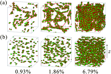 | ||
| Fig. 5 Snapshots of colloid distributions in NLCs at t = 2000tQ under (a) Ez = 0 and (b) Ez = 0.1. The particle volume fraction is 0.93%, 1.86% and 6.79% from the left to right panel. | ||
The defect pattern depends not only on the particle concentration, but also the way of preparation. When a sample is quenched into a nematic phase under an electric field as shown in Fig. 5(b), the director field is quickly aligned along the field in the early stage. This avoids defect entanglements. Then, no percolated DLs remain; DLs are localized around each particle, forming Saturn-ring defects for each particle. Fig. 6 plots the time development of the average particle displacement ΔR, which is calculated as
 | (5) |
 | ||
| Fig. 6 The time development of the particle displacement ΔR(t). We can see that particles tend to move over larger distances for a weaker external field. | ||
Finally, we mention a very interesting study by Wood et al., which shows colloidal gel formation by defect binding. They reported experimental and numerical observations on a colloid–NLC composite.41 They measured its mechanical strength and found that storage modulus is significantly increased when remaining DLs are percolated over the sample. A temperature quench from an isotropic phase to a nematic phase is not enough to synthesize composites of large elasticity. In order to obtain a percolated sample, or reconfigure defect structures, one has to apply strong shear to the sample.41 They also showed that heating above the clearing point suddenly transforms a gel to a liquid, which allows an instantaneous transformation from a gel to a liquid and the resulting disappearance of the elasticity. It may be worth noting that there is a difference in the processes of phase ordering and aggregation and in the percolation threshold between the numerical observation of Wood et al. and ours, which might be of technical origin.
4 Nematic liquid crystals in porous media
Next we consider a structure of more complicated topological characteristics. In porous media such as random nanostructures of silica gels, non-ergodic memory effects have been observed.51–58 Long-ranged elasticity and anchoring to solid surfaces make effects of a spatial confinement of NLCs by solids very significant. For example, for a NLC sandwiched by two parallel plates imposing homeotropic anchoring, the director field can be aligned uniformly without defects. Hence, the system memorizes the unique configuration, which is selected to minimize the elastic energy. If this stable pattern is perturbed by an external field, the director field quickly recovers the original state after the removal of the field. In porous networks, on the other hand, the global nematic order cannot go back to a uniquely determined state unlike the above case and long-lived remnant order remains even after switching off the external field.Such memory effects and slow glassy dynamics have been studied theoretically and numerically.54,56,60–64 In these studies, point-like defects which anchor the director field are introduced to mimic a random surface field. However, this approach cannot deal with the topological characteristics of a solid matrix. We have recently succeeded in studying effects of solid matrix topology on memory effects in collaboration with Bellini and Buscaglia.48 By means of Monte Carlo simulations considering ‘geometrical frustration’, we found that DLs topologically concatenated to the solid networks play significant roles in the memory effect and thus the memory effect crucially depends on the relationship between the topological characteristics of solid surfaces and the symmetry of an external field.
We employed lattice-based Monte Carlo simulations with the following Heisenberg model like Hamiltonian for spin nkα:
 | (6) |
The lattice space is partitioned into three portions in terms of pore structures. , and ![[scr P, script letter P]](https://www.rsc.org/images/entities/char_e52f.gif) represent the space filled with NLCs, solid objects and surfaces between them. The first term of eqn (6) describes the isotropic–nematic transition.59 In a bulk, the transition temperature is TIN ≅ 0.75J. The second and third terms represent the effects of the anchoring and external field Eα. A positive W imposes the homeotropic alignments at the surfaces. We carried out simulations with heat bath sampling at temperature T.48 Here, we set W = J = 1.
represent the space filled with NLCs, solid objects and surfaces between them. The first term of eqn (6) describes the isotropic–nematic transition.59 In a bulk, the transition temperature is TIN ≅ 0.75J. The second and third terms represent the effects of the anchoring and external field Eα. A positive W imposes the homeotropic alignments at the surfaces. We carried out simulations with heat bath sampling at temperature T.48 Here, we set W = J = 1.
4.1 Memory effects due to a topological constraint from solid surfaces
We quench these systems at T = 0.1(<TIN) and equilibrate them without a field (‘zero-field cooling’). For the porous matrices we run simulations up to the time t = 105tMC. The physical meaning of the temporal evolution of Monte Carlo simulations is sometimes a matter of debate. However, the method has been known to be very powerful and useful for studying glassy systems with slow relaxation, the dynamics of which is dominated by activation processes overcoming a free energy barrier.75,76 The zero-field-cooled states are locally well ordered because their local nematic order parameter Q is approximately the same as that of the bulk sample QB. At the same time, the systems are globally isotropic, and hence the tensorial order parameter averaged over the whole sample is 〈Qαβ〉 ≈ 0. To these disordered states, we apply an electric field pulse along the z axis for a certain duration (105 < t/tMC ≤ 2 × 10⁵) and then switch it off at t = 2 × 10⁵tMC (or 1.5 × 10⁵tMC). Fig. 7(a) and (b) plot the temporal change in the nematic order parameter along the field of NLC, Q(t) = 〈Qzz(t)〉, for RPM and BC, respectively. When the electric field is applied, the director is forced to be aligned along the field and the global order develops along that direction. The degree of the global ordering depends on the field strength. Upon removal of the field, the system relaxes to a metastable state with an intermediate degree of order, which we call a remnant order QM (see below for its precise definition). This is a clear indication that the system has a capability to memorize the field-induced order. Fig. 7(c) and (d) show the field-strength dependences of the order parameter in the presence of the field, QE, and QM, respectively, for RPM and BC. We can clearly see that BC possesses a higher memory capability than RPM; the difference between QE and QM for BC, which is a measure of the loss of memory, is much smaller than that for RPM.
 | ||
| Fig. 7 Time evolution of the global nematic order along the z axis. NLCs filled in (a) RPM and (b) BC are cooled at T = 0.1 without an external field up to t = 105tMC. During a period (105 < t/tMC < 2 × 10⁵), the external fields E with several strengths are applied along the z axis. The resulting temporal changes of QE and QM are plotted as functions of the field strength E for (c) RPM and (d) BC. | ||
In Fig. 8, we show patterns of DLs after the zero-field cooling at t = 105tMC in the three employed porous matrices. We visualize DLs inside the nematic domain, following the method described in ref. 77. After zero-field cooling, many DLs wander through the pores without contacting the surfaces even after a long annealing time for all the matrix structures. Here, the defect trajectories seem to be randomly entangled. The DLs form closed loops without edges and some of them are concatenated to the porous network. In Fig. 8, some DLs appear to terminate, but actually they are connected with DLs at the opposite side because of the periodic boundary conditions.48 After an application of a strong field E = 0.5 along the z axis, the defect pattern in BC transforms into a regular pattern consisting of loops laying perpendicularly to the z axis, whereas that in RPM changes to a different, but still randomly entangled configuration.
 | ||
| Fig. 8 Patterns of disclination lines (DLs) in three types of porous matrices: A random matrix (left), a bicontinuous pattern with a cubic symmetry (center) and a simple cubic array of spheres without contact (right). Top row: the structures of the porous structures employed. The second row: configurations of DLs after zero-field cooling, observed at t = 105tMC. The third row: configurations of DLs under an external field. Bottom row: configurations of DLs observed at t = 3 × 10⁵tMC. We apply a strong field (|E| = 0.5) along the z axis from 105tMC to 2 × 10⁵tMC. | ||
Obviously, frustration imposed by surface anchoring plays a crucial role in the memory effects described above. An enormously large number of possible topological states of a confined NLC suggests an apparent analogy to well-known frustrated systems such as spin and structural glasses, in which an exponentially large number of metastable states are separated by large energy barriers. The origin of frustration of our system is, however, quite different from that of these glass systems. For example, typical spin glasses are intrinsically frustrated because of the impossibility to simultaneously minimize coupling energies. In the case of confined NLCs, a topological constraint due to confinement provides frustration to an otherwise well-behaved system. The frustration is intrinsic to the system's Hamiltonian in the former, whereas extrinsic in the latter. This leads to a marked difference in the degree of order in a mesoscopic length scale: while the nematic order is well defined locally, at the length scale of the pores it is severely affected by geometrical frustration because of the impossibility to simultaneously match all the anchoring constraints without forming topological defects. Each metastable state can be characterized by its trajectory and twist of DLs wandering through the maze of a porous system. This geometrical frustration offers a possibility to design confining geometries that optimize the macroscopic function of the metastable states: ‘geometrical functionalization’ of materials.
. In the limit of a very strong field, DLs are forced against the surface regions for which the normal lies in the x–y plane. The application of a strong field may even break the anchoring. However, as the field is removed, the normal anchoring is recovered and DLs relax to the local elastic energy minimum while preserving in large part of the concatenation with the solid network forced by the field, thus keeping some memory of the field effect. This leaves the system in a new aligned stable state different from the zero-field-cooled disordered stable state. It is the structure of a porous matrix that determines the degree of the remnant order in the new aligned state, i.e., what fraction of DLs is preserved after the removal of a field. In regular porous media like BC, we can realize a situation where the DLs are well aligned after a strong field is applied along a compatible direction. Since such a loop configuration (Fig. 8) is energetically favoured and thus uniquely formed in BC, the remnant order reaches a well-defined plateau for strong external fields as shown in Fig. 7(d).
Interestingly, the relaxation of the orientational order of NLCs in porous media crucially depends on the geometry and topology. Fig. 9(a) and (b) compare the pore-size ![[small script l]](https://www.rsc.org/images/entities/i_char_e146.gif) dependences of the long-time relaxation behaviours of NLCs at constant T = 0.1 for RPM and BC, respectively. The relaxation after the removal of a strong field E = 1 is markedly different between RPM and BC. The relaxation of the global nematic order in BC is characterized by a single decay process and very well fitted by a stretched exponential,48
dependences of the long-time relaxation behaviours of NLCs at constant T = 0.1 for RPM and BC, respectively. The relaxation after the removal of a strong field E = 1 is markedly different between RPM and BC. The relaxation of the global nematic order in BC is characterized by a single decay process and very well fitted by a stretched exponential,48
| Q(t) = QM + ΔQSexp{−(t/τS)α}, | (7) |
 | (8) |
 | ||
| Fig. 9 The long-time relaxation process of the global nematic order after the removal of a strong field for (a) RPM and (b) BC with various pore sizes . In RPM, a very slow logarithmic decay mode is observed (see eqn (8)). | ||
The relaxation times of the fast stretched exponential decay τS for RPM and BC geometries are shown in Fig. 10(a). The values obtained in the two geometries match, indicating that the fast decay is a relaxation process common to the two systems and not associated with the change in defect configurations. τS grows as 2, a scaling generally found for the viscoelastic relaxation of nematics in conventional liquid crystal cells. Indeed, in these systems viscoelastic relaxation is expected to govern the evolution of the system from a field-induced ordered state to the configuration of the minimum elastic energy attainable without topological rearrangements of defects. In the case of BC, such a configuration is characterized by DLs stabilized by the surface geometry, so that no further relaxation takes place at all values. Our simulations indicate that the regular pattern consisting of loops shown in Fig. 8 is the global energy minimum state for BC.
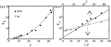 | ||
| Fig. 10 (a) The relaxation times for the fast stretched exponential decay τS for RPM and BC geometries as functions of the pore size . (b) Plots of τL in RPM against the mean pore size and the inverse temperature 1/T. | ||
When instead the topology attained after the fast relaxation is not stabilized by a surface geometry in a unique manner, rearrangements of DLs leading to a state with a lower energy are possible while accompanying a further relaxation, as for RPM. The slow relaxation involves topological rearrangements of defects. After the system has reached one of the local minima of its elastic energy states, that is, for t ≈ (2 − 3) × τS, DLs move only by thermal excitations. These continued motions lead DLs to transiently adopt conformations less energetically favoured, and thus foster DL collisions which may result in topological changes of defects, if energetically more favoured configurations can be accessed by the defect collisions. Such events in RPM can be directly seen in Fig. 11. A simple scaling analysis confirms that the activation barrier for such a DL collision is proportional to , leading to the relationship ln(τL/tMC) ∝ /T. Indeed, if a porous structure is uniformly enlarged by a factor of b while keeping the elastic constants and the DL connectivity unchanged, the free energy required for bringing two given DLs together grows linearly with the expansion factor b, as confirmed in Fig. 10(b). Inspection of the simulations also provides us with a clue to understand the logarithmic nature of the slow glassy relaxation (eqn (8)). Each DL collision event leading to a topological rearrangement is followed by a fast viscoelastic relaxation to a new state in which DLs experience a new energy landscape. This leads to a cascade effect, in which the activation energies are modified as the relaxation proceeds. More specifically, a logarithmic decay may be a consequence of an increase of the activation energy proportional to Q(t)−1. It is natural to expect that the DL reorganization requires higher energy barriers for further DL collisions as the time proceeds.48
 | ||
| Fig. 11 Snapshots of DLs in RPM at selected times during their relaxation process after the field removal. The comparisons between (a) and (b) as well as between (c) and (d) enable us to defect spontaneous topological changes in the DLs. The matrix pattern is not shown here to show the defect patterns better. | ||
 | ||
| Fig. 12 Thermal decay of the global nematic order along the z axis for various temperatures in porous media (a) with and (b) without topological constraint. The nematic liquid crystals are confined in (a) BC and (b) SCn, respectively. The isotropic–nematic transition temperature in a bulk is TIN ≅ 0.75. Even below TIN, the memory is spontaneously lost in the porous medium without topological constraint. | ||
4.2 Towards experimental realization of high memory effects
In the above, we find that BC provides one of the best surface topologies for NLC memory. However, the formation of such a regular structure is not so easy with currently available technologies. Fabrication of a regular porous structure with two-photon polymerization is a promising method and very recently applied to NLC memory.23 In this technique, the resolution of the laser is different in the x–y plane and along the z direction, and therefore all the channels do not have the same size, or the cross-section of the channels is not necessarily circular. Thus, it is important to evaluate the influence of imperfection and anisotropy on regular matrices by simulations for effective comparison with experiments. Hence, here we introduce anisotropy to ‘jungle gym’ matrices, which consist of cylindrical pillars oriented along the three orthogonal axes (see the inset of Fig. 13), and study its influence on the memory effect. The separation between the nearest parallel pillars is set to be = 16.
 | ||
| Fig. 13 Evolutions of the global nematic order along the z axis in ‘jungle gym’ porous networks (see the inset). During 105 < t/tMC < 1.5 × 10⁵, an external field is applied along the z direction, Ez = 0.5. We vary the radii of the pillars along x and y axes with fixing the radius of the z-cylinders to a2 = 2.8. | ||
Fig. 13 shows temporal evolutions of the global orientations along the z axis, before, during and after the application of an external electric field. We vary the radius a1, the radius of the channels in the x and y directions, while a2 = 2.8, the radius of the channels in the z direction. In the symmetric matrix (a1 = a2) the spontaneous global order is nearly zero and remaining DLs are randomly entangled after zero-field cooling (not shown here), as observed in BC and RPM. In asymmetric networks, on the other hand, the NLCs show spontaneous alignment: the global order parameter Q in the direction of the anisotropy is much bigger or smaller than zero if the pillars in that direction are bigger (a1 > a2) or smaller (a1 < a2), respectively. In matrices with large a1/a2, in particular, remaining DLs are already spontaneously aligned in x–y planes (not shown) even without any external field. This intrinsic alignment is directly caused by the anchoring interaction, and thus its quantity depends on the difference between surface areas projected on the three orthogonal planes. The mechanism of these spontaneous alignments will be reported elsewhere. The memory effects after the application of external fields are also affected by the anisotropic structures. In particular, the NLC for a1 = 1.4 shows a large decay mode as shown in Fig. 13. Pillar size and anisotropy are important parameters affecting the memory effects, as shown in Table 1, which lists the values of the memory parameter M = QM − QZFC, i.e., the difference between the remnant order parameter QM after field application and the order parameter QZFC after zero field cooling, for various cases. It appears that the ‘jungle gym’ scaffolds of a1 ≈ a2 show larger memory. However, the mechanisms of loss of memory are of two different kinds: in the structures with a1 ≪ a2 the DLs order induced by the applied field is completely lost. Since they recover their negative intrinsic orientations, they will retain memory only if the applied field is in the x or y direction. On the other hand, the structures with very high anisotropy and a1 ≫ a2 already have a very strong spontaneous alignment before the field is applied, therefore they do not ‘gain’ any more alignment from the application of an external field. The memory effects after the application of a field along the x direction is also important, in order to have a bistable (or multistable) system. Hence, symmetric porous structures are also preferred.48
 : M < 0.1, green
  : 0.1 < M < 0.3, orange
  : 0.3 < M < 0.6, red
  : 0.6 < M < 0.8, brown
  : M > 0.8. The half-circles represent the cases where memory is lost due to a ‘saturation’ effect because of high spontaneous ordering
| a 2/a1 | 1/2a2 | 3/4a2 | a 2 | 5/4a2 | 3/2a2 | 2a2 |
|---|---|---|---|---|---|---|
| 0.8 |

|

|

|

|

|

|
| 1.6 |

|

|

|

|

|

|
| 2.0 |

|

|

|

|

|

|
| 2.4 |

|

|

|

|

|

|
| 2.8 |

|

|

|

|

|

|
| 3.2 |

|

|

|

|

|

|
| 4.0 |

|

|

|

|

|

|
5 Dynamical coupling between NLC flow and defect patterns
5.1 Dragging a colloidal particle accompanying a Saturn-ring defect in NLCs
Here we focus on a remarkable feature of NLCs, i.e., the coexistence of orientational order and fluidity. Hydrodynamics for NLCs is different from that for isotropic liquids due to the dynamical coupling between the orientational degree of freedom and the hydrodynamic one. The viscosity of a NLC depends on the local orientational field and the elastic stress, called Ericksen stress, acts on the anisotropic liquid itself.1 Then, sedimenting or electrophoresing particles in nematic solvents show nonlinear flow behaviours, which are not seen in isotropic liquids, even in the Stokes regime. In particular, the coupling between topological defects and flow causes complex particle motions.26,78–82 For example, Stark and Ventzki reported lift-up motions, the directions of which are not parallel to the applied force, for a particle having a hyperbolic point defect.79,80 Furthermore, Lavrentovich et al. observed a drift motion of an electrophoresing particle in AC electric fields.81 Interestingly, its velocity is proportional to the square of the field strength.In ref. 68, we reported dynamics of a spherical particle accompanying a Saturn-ring defect. This is a quite interesting case where defect topology matters. We employed the same numerical scheme as that in Section 3. Fig. 14 shows representative snapshots of a particle moving in a NLC solvent. The background director field is oriented along the z axis. As shown in Fig. 14(a) and (b), we apply body forces to a particle towards the z and x directions, respectively. In NLCs, defect motions are caused not only by the convectional flow, but also by the rotational motion of the director field. The dynamic behaviours are well characterized by the Ericksen number Er, which is the ratio between the elastic stress and the viscous stress. The Ericksen number is roughly proportional to the particle velocity. We note that the key process of defect motion is the director rotation. In our problem, thus, the relevant viscosity for the Ericksen number is the rotational viscosity, not the shear viscosity as often assumed.68
 | ||
| Fig. 14 Representative snapshots of a particle moving in a NLC solvent. At rest, the background director is oriented along the z axis. We apply body forces for the particle towards the (a) z and (b) x directions. The radii of the particles are a = 8. The upper and lower panels in (a) correspond to regimes (a2) and (a3), respectively. The particle motions in (b) indicate regimes (b1) (upper) and (b2) (lower). | ||
When we apply a force in parallel to the bulk director field selected by an external field, we observed three regimes for the particle motions. (a1) When the particle velocity is slow enough (low Er), the accompanied defect is capable of keeping its most preferred position relative to the particle. (a2) As the particle velocity is increased (moderate Er), the defect can follow the particle, but the relative defect position is shifted backward from the preferred equator position at a quiescent state. Here the amount of the shift from the equator position increases with an increase in the particle velocity. (a3) If the velocity is increased further (high Er), the defect cannot catch up with the particle and the relative separation then starts to increase with time, which results in the increase in the elastic energy. When the elastic energy cost exceeds the anchoring energy, the anchoring state on the particle surface is broken and the defect disappears eventually. In Fig. 14(a), we show these moderate and strong pulling cases. In relation to this, we note that the following behaviour has been recently reported: for a fluid particle like an emulsion droplet, the behaviour is the same as that described above, whereas for a solid particle the defects shift forward.82 The reason for this discrepancy is not clear at this moment. We also note that defect motion may be strongly influenced by the flow-alignment coupling in the nematohydrodynamic equations.
More interesting is the case when a force is applied perpendicular to the bulk director field selected by an external field. Again we found three regimes, depending on Er. (b1) We observed that the particle motion is not parallel to the force direction for low Er regime. Since a portion of the defect in the front of the particle motion behaves as an obstacle for the particle motion, the particle tends to circumvent the defect and it chooses one of the two possible detours with the equal statistical weight.68 (b2) As the particle velocity is increased, the front part of the Saturn-ring defect penetrates to the particle, breaking the anchoring condition (see Fig. 14(b)). Upon this anchoring breaking, the particle can move just along the applied force. (b3) In a high Er regime, a full portion of the disclination loop disappears: flow-induced disanchoring transition. The degree of the off-axis motion in (b1) depends on the strength of the homeotropic anchoring condition: a particle with weaker anchoring surface can be driven more parallel to the field direction. This suggests an interesting possibility for separating particles in terms of their surface properties.68 This may offer a new method for electrophoretic separation of colloids or proteins in terms of their surface properties.
5.2 Flow of NLCs in a porous matrix
Recently, flow behaviours of NLCs in porous networks or microfluidic cavities have attracted much attention.49,83–85 We recently reported a lattice Boltzmann simulation on flow properties of a NLC in a BC matrix.86,87Fig. 15 shows a switching process of the defect pattern in a BC matrix induced by flow. Initially, we prepare a regular defect pattern by applying an electric field along the z axis, as shown in the second row of Fig. 8. Then, we start to flow the nematic solvent in BC towards the x direction at t = 0. When the flow speed is slow enough, the defects stay at their preferred positions. Under a moderate flow speed, the DL loops laying x–y plains change their orientation to a new direction. Because of the multistability of this pattern, the new orientation is stable even after the flow is stopped. So, we can say that flow direction can be recorded as the defect pattern in the porous network. This switching behaviour is similar to that caused by an electric or a magnetic field, as discussed in Section 4.48 We found that the resistance coefficient relating the flow speed to the force depends on the director pattern. This leads to an abrupt increase of the flow speed upon this switching. We also expect that the flow path can be dynamically selected by manipulating local defect configurations. As the flow speed is increased further, cyclic motion of the trapped defects is observed, and its characteristic frequency depends on whether or not the defects are topologically concatenated to the network. These nonlinear behaviours are strongly influenced by the anchoring condition. The conventional argument based on the Ericksen number does not take the anchoring interaction into account. In microfluidic devices and porous networks, the coupling between flow and anchoring is not negligible, as in the above case of colloids driven in a NLC. This will open up an interesting possibility of applications to flow control.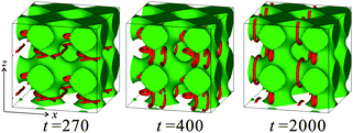 | ||
| Fig. 15 Switching process of the multistable defect pattern in a cubic porous medium. The NLC solvent is flowing towards the x direction. | ||
6 Conclusion and outlook
In this article, we mainly review our numerical studies on topological defects of NLCs formed by geometrical frustration. In complex geometries with curved surfaces, frustrations between the elastic field favouring the undistorted nematic order and the anchoring effect distorting the order lead to the formation of stable defects, whose spatial configuration reflects how orientational order is organized in space. Since the energy barrier required for a change of the defect topology is far beyond the thermal energy, structures stabilized by defects are exceptionally robust among various structures in soft matter. The coexistence of this robustness of the defect structure and flowing ability of NLCs is a quite unique opportunity of defect engineering, which applies defects to create new functions. Defect engineering discussed here offers interesting applications of defects, which have been thought to be undesirable in conventional technology. Optical manipulation of defects is a quite promising way to control a defect configuration in liquid crystals.10,39 While we are focussing here only on nematics, we note that defects in a smectic A phase can also be manipulated and patterned optically88 and also geometrically.89–92We show here mainly two types of NLC systems, in which the homeotropic anchoring to surfaces is assumed: isolated colloidal particles immersed in a NLC, where solids are mobile, and a NLC confined in porous media, where solids are immobile. For the former, we found a new type of metastable state, in which a ‘figure of eight’ disclination entangles around a pair of particles and strongly binds them. This effective interaction mediated by entangled DLs is also relevant for many particles, so that the particles can be irreversibly self-organized.
For the latter, stable defects formed in frustrated geometries have attracted many researchers for about two decades. However, global energy minimum states have been mainly considered so far. If only point defects remain in the system, they can move towards their most favourable positions without topological constraints, and then the system can reach the global energy minimum state. On the other hand, DLs are often trapped at high energy configurations because of their entanglement effects. However, such metastable states are not necessarily unfavourable. The entangled DLs now provide us with fascinating and promising tools to design systems with multistabilities. Indeed, in NLCs confined in porous media, remaining DLs wander through the channels of the solid network while keeping a large number of possible trajectories. Random porous media provide highly degenerate metastable states, leading to glassy slow dynamics, a topic of fundamental interest. After the removal of an external field, the system exhibits two relaxation modes in the global order parameter. The slower mode represents a thermally activated process, which accompanies the topological rearrangements of the DL pattern, and gives rise to the memory effect of topological origin. We demonstrated that the slow mode can be suppressed by designing the topology of matrix structures, more precisely, by removing the degeneracy of metastable states and realizing a unique topologically stable structure. This allows us to drastically enhance the capability of the memory effect. Here the bicontinuity of the matrix and the resulting irreducibility of DLs are the key to the robustness of the memory.
As emphasized in this review article, liquid crystals provide an ideal opportunity for investigating how topological constraint can affect not only self-organization of an ordered structure but also its dynamical behaviour. Geometrical frustration and the resulting glassy behaviour including memory effects are also important subjects. We would like to stress that the concept of defect science and engineering described in this paper may be relevant to strongly correlated electron systems and defect dynamics in Bose–Einstein condensates, including superconductors, liquid He, and laser cooled systems. What is common to these systems is the coexistence of order and fluidity. Here we consider only the topology of DLs but do not consider the degree of freedom of twist explicitly. Liquid crystalline phases such as nematic and smectic A do not have spontaneous topological defects, whereas some phases with chiral symmetry breaking, such as twisted grain boundary and cholesteric blue phases, have defects as their intrinsic structural elements. Thus, it is also interesting to consider the effects of chirality as well as effects of geometrical frustration on intrinsic defects.
Research on these topics has just started and is still immature. We hope that this review article would facilitate further intensive research that may lead us to the basic understanding of this fascinating physics on topology and its applications.
Acknowledgements
The authors are indebted to Tommaso Bellini and Marco Buscaglia for their collaboration and fruitful discussion on memory effects in porous media. T.A. and H.T. are grateful to the JSPS Core-to-Core Program “International research network for non-equilibrium dynamics of soft matter”. T.A. acknowledges KAKENHI (no. 24540433 and 23244088). F.S. acknowledges JSPS fellowship support for travel and stay in Kyoto University. H.T. acknowledges a grant-in-aid from the Ministry of Education, Culture, Sports, Science and Technology, Japan and Aihara Project, the FIRST program from JSPS, initiated by CSTP. A part of the computational work was performed using the facilities at the Supercomputer Center, Institute for Solid State Physics, University of Tokyo.References
- P. G. de Gennes and J. Prost, The Physics of Liquid Crystals, Oxford University Press, Oxford, 2nd edn, 1993 Search PubMed.
- P. M. Chaikin and T. C. Lubensky, Principles of Condensed Matter Physics, Cambridge University Press, Cambridge, 1995 Search PubMed.
- M. Kleman and O. D. Lavrentovich, Soft Matter Physics: An Introduction, Springer-Verlag, 2003 Search PubMed.
- G. P. Alexander, B. G. Chen, E. A. Matsumoto and R. D. Kamien, Rev. Mod. Phys., 2012, 84, 497–514 CrossRef CAS.
- A. Vilenkin and E. Shellard, Cosmic strings and other topological defects, Cambridge University Press, 2000 Search PubMed.
- T. W. B. Kibble, J. Phys. A: Math. Gen., 2001, 9, 1387 CrossRef.
- I. Chuang, N. Durrer, R. Turok and B. Yurke, Science, 1991, 251, 1336–1342 CAS.
- H. Kikuchi, M. Yokota, Y. Hisakado, H. Yang and T. Kajiyama, Nat. Mater., 2002, 1, 64–68 CrossRef CAS.
- P. Poulin, H. Stark, T. C. Lubensky and D. A. Weitz, Science, 1997, 275, 1770–1773 CrossRef CAS.
- I. Muševič, M. Škarabot, U. Tkalec, M. Ravnik and S. Žumer, Science, 2006, 2006, 954–958 CrossRef.
- I. Chuang, N. Turok and B. Yurke, Phys. Rev. Lett., 1991, 66, 2472–2475 CrossRef CAS.
- K. Tojo, A. Furukawa, T. Araki and A. Onuki, Eur. Phys. J. E: Soft Matter Biol. Phys., 2009, 30, 55–64 CrossRef CAS.
- H. Tanaka and T. Araki, Phys. Rev. Lett., 2000, 85, 1338–1341 CrossRef CAS.
- C. Lapointe, A. Hultgren, D. M. Silevitch, E. J. Felton, D. H. Reich and R. L. Leheny, Science, 2004, 303, 652 CrossRef CAS.
- F. R. Hung, Phys. Rev. E: Stat., Nonlinear, Soft Matter Phys., 2009, 79, 021705 CrossRef.
- J. Dontabhaktuni, M. Ravnik and S. Žumer, Soft Matter, 2012, 8, 1657–1663 RSC.
- B. Senyuk, Q. Liu, S. He, R. D. Kamien, R. B. Kusner, T. C. Lubensky and I. I. Smalyukh, Nature, 2013, 493, 200–205 CrossRef CAS.
- S. C. Glotzer, Science, 2004, 306, 419–420 CrossRef CAS.
- A. van Blaaderen, Nature, 2006, 439, 545–546 CrossRef CAS.
- M. Conradi, M. Ravnik, M. Bele, M. Zorko, S. Žumer and I. Muševič, Soft Matter, 2009, 5, 3905–3912 RSC.
- H. Tanaka, J. Phys.: Condens. Matter, 2000, 12, R207 CrossRef CAS.
- G. Gompper, M. Schick and S. Milner, Phys. Today, 1995, 48, 91 CrossRef.
- F. Serra, S. M. Eaton, R. Cerbino, M. Buscaglia, G. Cerullo, R. Osellame and T. Bellini, Adv. Funct. Mater., 2013 DOI:10.1002/adfm.201203792.
- E. M. Terentjev, Phys. Rev. E: Stat. Phys., Plasmas, Fluids, Relat. Interdiscip. Top., 1995, 51, 1330–1337 CrossRef CAS.
- O. V. Kuksenok, R. W. Ruhwandl, S. V. Shiyanovskii and E. M. Terentjev, Phys. Rev. E: Stat. Phys., Plasmas, Fluids, Relat. Interdiscip. Top., 1996, 54, 5198–5203 CrossRef CAS.
- H. Stark, Phys. Rep., 2001, 351, 387–474 CrossRef CAS.
- H. Mori and H. Nakanishi, J. Phys. Soc. Jpn., 1988, 57, 1281–1286 CrossRef.
- J.-C. Loudet, P. Barois and P. Poulin, Nature, 2000, 407, 611–613 CrossRef CAS.
- O. Mondain-Monval, J. C. Dedieu, T. Gulik-Krzywicki and P. Poulin, Eur. Phys. J. E: Soft Matter Biol. Phys., 1999, 12, 167–170 CAS.
- J.-C. Loudet, P. Barois, P. Auroy, P. Keller, H. Richard and P. Poulin, Langmuir, 2004, 20, 11336–11347 CrossRef CAS.
- K. Kita, M. Ichikawa and Y. Kimura, Phys. Rev. E: Stat., Nonlinear, Soft Matter Phys., 2008, 77, 041702 CrossRef.
- R. W. Ruhwandl and E. M. Terentjev, Phys. Rev. E: Stat., Nonlinear, Soft Matter Phys., 1997, 55, 2958 CrossRef CAS.
- O. Guzmán, E. B. Kim, S. Grollau, N. L. Abbott and J. J. de Pablo, Phys. Rev. Lett., 2003, 91, 235507 CrossRef.
- O. Guzmán, N. L. Abbott and J. J. de Pablo, J. Polym. Sci., Part B: Polym. Phys., 2005, 43, 1033–1040 CrossRef.
- S. Žumer, Modeling of constrained nematic order: from defects to colloidal structures, Plenary talk at 21st International Liquid Crystal Conference, Keystone, Colorado, July 2–7, 2006 Search PubMed.
- M. Ravnik, M. Škarabot, S. Žumer, U. Tkalec, I. Poberaj, D. Baič, N. Osterman and I. Muševič, Phys. Rev. Lett., 2007, 99, 247801 CrossRef CAS.
- M. Ravnik and S. Žumer, Soft Matter, 2009, 5, 269–274 RSC.
- M. Ravnik and S. Žumer, Soft Matter, 2009, 5, 4520–4525 RSC.
- U. Tkalec, M. Ravnik, S. Čopar, S. Žumer and I. Muševič, Science, 2011, 333, 62–65 CrossRef CAS.
- V. S. R. Jampani, M. Škarabot, M. Ravnik, S. Čopar, S. Žumer and I. Muševič, Phys. Rev. E: Stat., Nonlinear, Soft Matter Phys., 2011, 84, 031703 CrossRef CAS.
- T. A. Wood, J. S. Lintuvuori, A. B. Schofield, D. Marenduzzo and W. C. K. Poon, Science, 2011, 334, 79–83 CrossRef CAS.
- T. Araki and H. Tanaka, Phys. Rev. Lett., 2006, 97, 127801 CrossRef.
- G. P. Crawford and S. Žumer, Liquid Crystals in Complex Geometries Formed by Polymer and Porous Networks, Taylor and Francis, London, 1996 Search PubMed.
- I. Muševič and S. Žumer, Nat. Mater., 2011, 10, 266–268 CrossRef.
- Z. Bradač, S. Kralj and S. Žumer, Phys. Rev. E: Stat. Phys., Plasmas, Fluids, Relat. Interdiscip. Top., 1998, 58, 7447–7454 CrossRef.
- S. Kralj and S. Žumer, Phys. Rev. E: Stat. Phys., Plasmas, Fluids, Relat. Interdiscip. Top., 1995, 51, 366–379 CrossRef CAS.
- A. Shams, X. Yao, J. O. Park, M. Srinivasarao and A. D. Rey, Soft Matter, 2012, 8, 11135 RSC.
- T. Araki, M. Buscaglia, T. Bellini and H. Tanaka, Nat. Mater., 2011, 10, 303–309 CrossRef CAS.
- F. Serra, K. C. Vishnubhatla, M. Buscaglia, R. Cerbino, R. Osellame, G. Cerullo and T. Bellini, Soft Matter, 2011, 7, 10945–11032 RSC.
- D. L. Stein, Phys. Rev. A: At., Mol., Opt. Phys., 1979, 19, 1708–1711 CrossRef CAS.
- X. Wu, W. I. Goldburg, M. X. Liu and J. Z. Xue, Phys. Rev. Lett., 1992, 69, 470–473 CrossRef CAS.
- T. Bellini, N. Clark, C. Muzny, L. Wu, C. Garland, D. Schaefer and B. Oliver, Phys. Rev. Lett., 1992, 69, 788–791 CrossRef CAS.
- G. S. Iannacchione, G. P. Crawford, S. Žumer, J. W. Doane and D. Finotello, Phys. Rev. Lett., 1993, 71, 2595–2598 CrossRef CAS.
- T. Bellini, M. Buscaglia, C. Chiccoli, F. Mantegazza, P. Pasini and C. Zannoni, Phys. Rev. Lett., 2002, 88, 245506 CrossRef CAS.
- D. Kang, J. E. Maclennan, N. A. Clark, A. A. Zakhidov and R. H. Baughman, Phys. Rev. Lett., 2001, 86, 4052–4055 CrossRef CAS.
- M. Buscaglia, T. Bellini, C. Chiccoli, F. Mantegazza, P. Pasini, M. Rotunno and C. Zannoni, Phys. Rev. E: Stat., Nonlinear, Soft Matter Phys., 2006, 74, 011706 CrossRef CAS.
- D. E. Feldman, Phys. Rev. Lett., 2000, 84, 4886–4889 CrossRef CAS.
- F. Serra, M. Buscaglia and T. Bellini, Mater. Today, 2011, 14, 488–494 CrossRef CAS.
- P. A. Lebwohl and G. Lasher, Phys. Rev. A: At., Mol., Opt. Phys., 1972, 6, 426–429 CrossRef.
- A. Maritan, M. Cieplak, T. Bellini and J. Banavar, Phys. Rev. Lett., 1994, 72, 4113–4116 CrossRef CAS.
- J. Ilnytskyi, S. Sokołowski and O. Pizio, Phys. Rev. E: Stat. Phys., Plasmas, Fluids, Relat. Interdiscip. Top., 1999, 59, 4161–4168 CrossRef CAS.
- M. Rotunno, M. Buscaglia, C. Chiccoli, F. Mantegazza, P. Panisi, T. Bellini and C. Zannoni, Phys. Rev. Lett., 2005, 94, 097802 CrossRef CAS.
- L. Petridis and E. M. Terentjev, Phys. Rev. E: Stat., Nonlinear, Soft Matter Phys., 2006, 74, 051707 CrossRef CAS.
- J. M. Fish and R. L. C. Vink, Phys. Rev. Lett., 2010, 105, 147801 CrossRef CAS.
- J. Yamamoto and H. Tanaka, Nature, 2001, 409, 321–325 CrossRef CAS.
- J. Fukuda and H. Yokoyama, Eur. Phys. J. E: Soft Matter Biol. Phys., 2001, 4, 389–396 CrossRef CAS.
- R. Yamamoto, Phys. Rev. Lett., 2001, 87, 075502 CrossRef CAS.
- T. Araki and H. Tanaka, J. Phys.: Condens. Matter, 2006, 18, L193–L203 CrossRef CAS.
- H. Tanaka and T. Araki, Chem. Eng. Sci., 2006, 61, 2108–2141 CrossRef CAS.
- C. Völtz, Y. Maeda, Y. Tabe and H. Yokoyama, Phys. Rev. Lett., 2006, 97, 227801 CrossRef.
- E. B. Kim, O. Guzmán, S. Grollau, N. L. Abbott and J. J. de Pablo, J. Chem. Phys., 2004, 121, 1949–1961 CrossRef CAS.
- S. Čopar and S. Žumer, Phys. Rev. Lett., 2011, 106, 177801 CrossRef.
- S. Čopar, T. Porenta and S. Žumer, Phys. Rev. E: Stat., Nonlinear, Soft Matter Phys., 2011, 84, 051702 CrossRef.
- R. D. Kamien, Rev. Mod. Phys., 2002, 74, 953–971 CrossRef.
- K. Binder and W. Kob, Glassy materials and disordered solid, World Scientific Pub., 2005 Search PubMed.
- A. T. Ogielski, Phys. Rev. B: Condens. Matter Mater. Phys., 1985, 32, 7384–7398 CrossRef CAS.
- P. E. Lammert, D. S. Rokhsar and J. Toner, Phys. Rev. E: Stat. Phys., Plasmas, Fluids, Relat. Interdiscip. Top., 1995, 52, 1778–1800 CrossRef CAS.
- J. Fukuda, H. Stark, M. Yoneya and H. Yokoyama, J. Phys.: Condens. Matter, 2004, 16, S1957 CrossRef CAS.
- H. Stark and D. Ventzki, Phys. Rev. E: Stat., Nonlinear, Soft Matter Phys., 2001, 64, 031711 CrossRef CAS.
- H. Stark and D. Ventzki, Europhys. Lett., 2002, 57, 60 CrossRef CAS.
- O. D. Lavrentovich, I. Lazo and O. P. Pishnkyak, Nature, 2010, 467, 947–950 CrossRef CAS.
- B. T. Gettelfinger, J. A. Moreno-Razo, G. M. Koenig Jr, J. P. Hernández-Ortiz, N. L. Abbott and J. J. de Pablo, Soft Matter, 2010, 6, 896–901 RSC.
- A. Sengupta, U. Tkalec and C. Bahr, Soft Matter, 2011, 7, 6542–6459 RSC.
- A. Sengupta, C. Pieper, J. Enderlein, C. Bahr and S. Herminghaus, Soft Matter, 2013, 9, 1937 RSC.
- A. Sengupta, U. Tkalec, M. Ravnik, J. M. Yeomans, C. Bahr and S. Herminghaus, Phys. Rev. Lett., 2013, 110, 048303 CrossRef.
- T. Araki, Phys. Rev. Lett., 2012, 109, 257801 CrossRef.
- T. Araki, Proceedings of the 4th International Symposium on “Slow Dynamics in Complex Systems”, 2012 Search PubMed.
- Y. Iwashita and H. Tanaka, Phys. Rev. Lett., 2003, 90, 45501 CrossRef.
- F. Nallet and J. Prost, Europhys. Lett., 2007, 4, 307 CrossRef.
- Y. Iwashita and H. Tanaka, Phys. Rev. E: Stat., Nonlinear, Soft Matter Phys., 2008, 77, 041706 CrossRef.
- D. K. Yoon, M. C. Choi, Y. H. Kim, M. W. Kim, O. D. Lavrentovich and H.-T. Jung, Nat. Mater., 2007, 6, 866–870 CrossRef CAS.
- Y. H. Kim, D. K. Yoon, H. S. Jeong, O. D. Lavrentovich and H. T. Jung, Adv. Funct. Mater., 2011, 21, 610–627 CrossRef CAS.
| This journal is © The Royal Society of Chemistry 2013 |