 Open Access Article
Creative Commons Attribution 3.0 Unported Licence
Combining 3D printing and liquid handling to produce user-friendly reactionware for chemical synthesis and purification†
Philip J.
Kitson
,
Mark D.
Symes
,
Vincenza
Dragone
and
Leroy
Cronin
*
WestCHEM, School of Chemistry, The University of Glasgow, Glasgow, G12 8QQ, UK. E-mail: Lee.Cronin@glasgow.ac.uk; Web: http://www.croninlab.com
First published on 10th June 2013
Abstract
We use two 3D-printing platforms as solid- and liquid-handling fabricators, producing sealed reactionware for chemical synthesis with the reagents, catalysts and purification apparatus integrated into monolithic devices. Using this reactionware, a multi-step reaction sequence was performed by simply rotating the device so that the reaction mixture flowed through successive environments under gravity, without the need for any pumps or liquid-handling prior to product retrieval from the reactionware in a pure form.
Introduction
3D-printing is an emerging technology which promises to revolutionize many areas of manufacturing processes, transforming the relationships between the design, manufacture and operation of functional devices.1,2 In recent years there has been considerable interest in 3D-printing technologies for large-scale industrial prototyping,3 the production of tissue growth scaffolds4–9 and biomimetic microvascular systems,10,11 and the manufacture of bespoke electronic12 and pneumatic devices.13–15 However, 3D-printing could also make a significant impact in the field of chemical synthesis research and manufacturing, in particular because of the ease and economy with which bespoke reactors can be designed and compounds manufactured. Indeed the first results from the computer design and 3D printing of bespoke reactors or ‘reactionware’ demonstrating the utility of the concept have recently been presented.16–18 Moreover, the range of 3D-printers currently available permits a broad spectrum of materials to be printed, including solutions of comparatively low viscosity, allowing some of these printers to act in effect as inexpensive liquid/gel-handling robots thereby allowing the 3D printer to be used as a reactionware fabricator, as well as a robotic reagent dispenser. This means that reagents and catalysts can be added into reactionware without the need for chemical handling by a human user, thus allowing complex manipulations to be more precisely controlled, optimised, and shared with other researchers opening up chemistry to a wider range of practitioners, as well as developing new research tools. However, in order for the full potential of 3D-printed reactionware to be realised, it must be possible to conduct and purify multi-step reactions in printed devices, so that a single desired product can be isolated from reaction mixtures.With the need for control over extended reaction sequences and ultimate product purification, separation and isolation in mind, we considered the situation illustrated in Scheme 1, whereby a printer (or suite of printers) is able to construct a reactor with an embedded sequence of reagents and catalysts with only minimal handling of actual chemicals by the user. Furthermore, we hypothesized that by printing self-contained chemical reactors where starting materials, reagents, catalysts and purification devices were all incorporated into the reactionware in a pre-defined sequence, multi-step chemical syntheses could be performed outside the laboratory setting and by those without extensive chemical knowledge by simply rotating an appropriately designed reactor according to a specific schedule and letting gravity pull the reactants through the various chambers in the device.
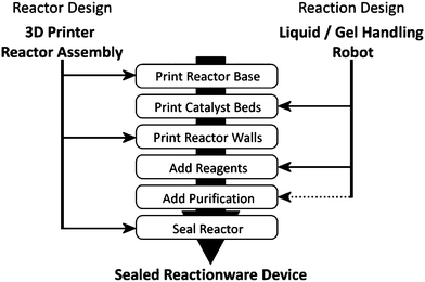 | ||
| Scheme 1 Fabrication scheme for the integration of 3D-printing techniques with automated liquid handling to produce sealed reactionware for multi-step syntheses. Dotted line indicates the only process not automated in the current work. | ||
To illustrate this concept, we chose a three-step organic reaction sequence consisting of three different standard organic transformations that are used in a wide range of chemical syntheses: (i) Diels–Alder cyclization, a widely used C–C bond forming reaction employed by synthetic chemists19,20 followed by (ii) the formation of an imine and finally (iii) hydrogenation of the imine to the corresponding secondary amine.21
Results and discussion
Reactor design and fabrication
To perform this sequence of transformations, the reactors were designed with three reaction chambers, one for each of the successive stages in the sequence (see Fig. 1), with the reaction mixture being transferred from chamber to chamber upon the completion of each reaction step by rotating the device. Two device designs were realised; one in which the reactor was open to the environment, allowing the introduction of reaction starting materials and reagents at various points in the process, and one in which all the necessary materials were introduced into the device during the fabrication process, producing a self-contained chemical reactor which included a short silica purification column (see ESI Fig. S1†). The reaction chambers were designed as cubes of side 20.0 mm with circular passages of diameter 4.0 mm connecting the chambers (wide enough to allow the reaction mixture to flow through readily upon rotation of the device). The purification column space printed into the sealed reactor design was 24.0 mm in length with a square cross section of 49.0 mm2. The reaction sequence in each reactor proceeded in a controlled fashion and in the correct order upon rotation of the device, such that the products of one step only flowed into the next chamber for further reaction if the orientation of the device was correct.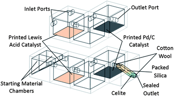 | ||
| Fig. 1 Schematic diagram of the 3D-printed sequential reactors; (top) open reactor featuring inlet and outlet ports for the introduction and retrieval of reactants/products, (bottom) sealed reactor with starting material reservoirs, incorporating packed silica purification column. | ||
The fabrication of the reactors was achieved using two 3D-printing machines: a Fab@Home Version 0.24 RC6 freeform fabricator,22 alongside a Bits from Bytes 3DTouch™ 3D-printer,23 both of which systems rely on layer deposition methods to print 3D structures. The main architecture was printed using the 3DTouch™ printer from polypropylene, which was found to provide a suitably inert material for the solvents and reagents necessary for the organic transformations performed (see ESI†).
After printing the base of the reactor architecture, printing was paused and the unfinished device transferred to the Fab@home machine where the catalyst components were printed-in by controlled deposition of the materials in the correct places in the structure architecture. These catalyst components were introduced by first incorporating the active reagents into a matrix which would allow the material to be extruded by the Fab@home printer. In this case the matrix chosen was an acetoxy silicone polymer, according to a modified literature procedure17 (see ESI for details†). The first and third reactions in the synthetic sequence required catalysts for effective completion of the reactions. Hence, into the first chamber was printed montmorillonite K10 Lewis acid matrix (which is known to catalyse Diels–Alder reactions24,25) and into the third chamber was printed a Pd/C reduction catalystmatrix (see Fig. 2, and ESI Fig. S2†). Once the catalytic materials had been printed, small magnetic stirrer bars were placed in each of the three reaction chambers and the reactor was returned to the 3DTouch™ to complete fabrication (see ESI†). In the case of the sealed reactor the printing was paused once again near the end of the fabrication and the unfinished reactor returned to the Fab@home device to allow the starting materials and reagents to be introduced into the appropriate chambers and to allow the packing of the purification column with a slurry of silica gel in hexane, which was tamped into the printed column space by hand.
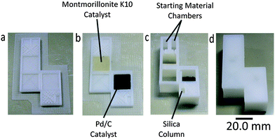 | ||
| Fig. 2 (a) Reactor base with purification column before printing of catalyst regions. (b) Reactor base with purification column after printing of catalyst regions. (c) Fabricated reactor with purification column after addition of starting materials, reagents and packing of silica. (d) Final sealed reactor. | ||
The chemical transformations carried out in the printed reactor had previously been optimized by traditional synthetic methods so that the correct parameters (i.e. reaction time and stoichiometry) could be applied to the printed reactor system. The first reaction in the sequence was a Lewis acid catalyzed Diels–Alder cyclization between a diene (in this case a substituted cyclopentadiene) and acrolein, forming a bicyclic-bridged structure with a pendant aldehyde group (1). In the next step this aldehyde group reacted with aniline to produce an imine (2), which was subsequently reduced in the final reaction of the sequence, using a Pd/C catalyst in conjunction with triethylsilane (TES) as a source of hydrogen, to give the secondary amine final product, 3 (see Fig. 3).
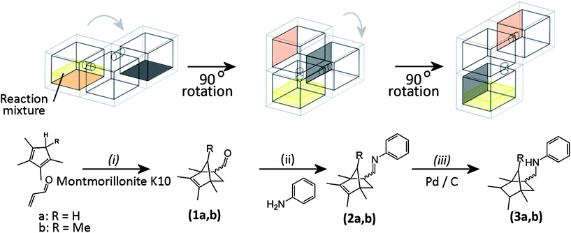 | ||
| Fig. 3 Schematic diagram of the multi-step reaction sequence in both open and sealed reactionware once the sequence was initiated by mixing the starting materials: only the main (reaction) chambers are shown for clarity, grey arrows represent the direction of rotation of the reactionware during the sequence. Reaction conditions for the open reactor: (i) chloroform, room temperature, 5 h; (ii) chloroform, room temperature, 2 h; (iii) triethylsilane in methanol, room temperature, 20 min. Reaction conditions for the sealed reactor: (i) 5% diethyl ether/hexane, room temperature, 5 h; (ii) room temperature, 2 h; (iii) room temperature, 20 min. For the open reactor chloroform was used as an initial solvent with TES and aniline introduced for the later reaction steps, whereas for the sealed reactor hexane/ether was used with a mixture of TES and aniline deposited in the second reaction chamber during fabrication. The reagents were induced to flow into subsequent reaction chambers by rotation of the device through 90° intervals. | ||
In the case of the open reactor, solutions of the initial reagents; acrolein, the appropriate n-methylcyclopenta-1,3-diene in chloroform were introduced into the first reaction chamber by injection through the input ports designed into the reactor. The reactor was then placed on a stirring plate and the mixture stirred at room temperature for 5 hours. Subsequent rotation of the reactor through 90° allowed the reaction mixture to pass into the second chamber (see Fig. 3) whilst a solution of aniline in chloroform was introduced through the initial inlet ports and immediately allowed to flow into the second reaction chamber. In this second chamber the reaction mixture was stirred for a further 2 hours to allow complete formation of the imine product. Once this transformation was complete the reagents for the third transformation (a mixture of triethylsilane and methanol) were added through the initial inlet port and allowed to flow into the second reaction chamber. The device was then rotated again through 90° to allow the reaction mixture to flow finally into the third reaction chamber, where it came into contact with the Pd/C catalytic matrix. The reaction was stirred in the third chamber for 20 minutes before the reactor was rotated once again to retrieve the crude reaction mixture from the outlet opening from chamber 3 (see ESI for more details†).
Comparison of the 1H NMR spectra of the crude reaction mixtures taken from the 3D-printed reactors with those from the same transformations carried out in traditional glassware (see ESI Fig. S4 and S5†) showed that there was no significant difference in the reaction outcomes of any of the reaction steps due to the materials present in the 3D-printed reactor (i.e. the polypropylene architecture and siliconecatalystmatrix did not influence the outcome of the reaction). This indicated the suitability of reactors composed of these materials for organic syntheses. The final products (3a, b) were obtained after column chromatography as a mixture of the endo- and exo-isomers of the initial Diels–Alder cyclization step, with major product![[thin space (1/6-em)]](https://www.rsc.org/images/entities/char_2009.gif) :
:![[thin space (1/6-em)]](https://www.rsc.org/images/entities/char_2009.gif) minor product ratios of 1
minor product ratios of 1![[thin space (1/6-em)]](https://www.rsc.org/images/entities/char_2009.gif) :
:![[thin space (1/6-em)]](https://www.rsc.org/images/entities/char_2009.gif) 0.3 for 3a and 1
0.3 for 3a and 1![[thin space (1/6-em)]](https://www.rsc.org/images/entities/char_2009.gif) :
:![[thin space (1/6-em)]](https://www.rsc.org/images/entities/char_2009.gif) 0.2 for 3b (the assignment of major product as the endo-isomer is based on literature precedent26). These product ratios were carried through the reaction sequence unaffected by transformations subsequent to the initial cyclization (see Fig. 4).
0.2 for 3b (the assignment of major product as the endo-isomer is based on literature precedent26). These product ratios were carried through the reaction sequence unaffected by transformations subsequent to the initial cyclization (see Fig. 4).
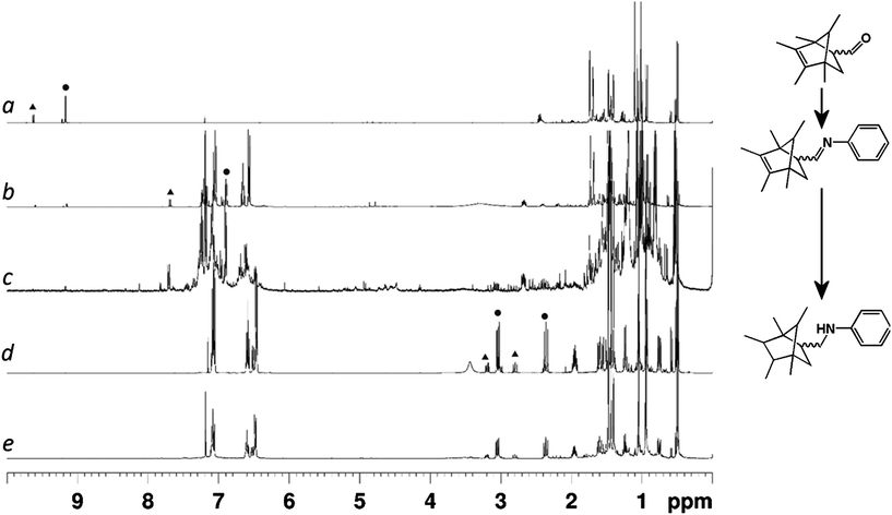 | ||
| Fig. 4 1H NMR (400 MHz, 298 K, CDCl3) spectra of the reaction mixtures extracted from the 3D-printed reactors at various stages of the reaction sequence. (a) After Diels–Alder cyclization of initial starting materials. (b) After imine formation with aniline. (c) Crude reaction mixture after final reaction without purification. (d) Final product after full purification using traditional column chromatography from the open reactor. (e) Final product after built-in purification using the sealed reactor. Peaks corresponding to aldehyde, imine and newly formed aliphatic protons are highlighted in spectra (a), (b) and (d) with circles indicating the major product signals and triangles indicating minor product signals. | ||
In the case of the sealed reactor, chloroform was found to be a poor solvent for the final-stage purification of the product on the in-built silica column, due to poor separation of product from unreacted starting materials (mostly aniline) and byproducts produced during the previous steps. Hence in this case hexane was used as the major solvent in the reaction system. The necessary starting materials were added to the reactor during the fabrication process, with solutions of acrolein and substituted cyclopentadiene (in 5% diethyl ether/hexane) contained in an additional set of chambers prior to the first reaction chamber which were designed such that the reaction could be initiated by tilting the reactor at a 45° angle to allow the starting materials to flow into the first reaction chamber (see Fig. 1). The reagents necessary for the second and third reactions in the sequence were incorporated into the second reaction chamber. Thus all the reagents necessary to synthesise compounds 3a and 3b were present in a single monolithic and self-contained reactor. The physical separation of the reaction steps enforced by the reactor design is crucial as all the reagents are now present in the reactor at the same time, but the desired product can only be obtained when the order and location of mixing is strictly controlled. Purification of the reaction mixture was achieved by pushing a needle through the sealed opening at the bottom of the purification column (by hand) and then manually drawing the crude reaction mixture through the column with a syringe. Two washings of the column with hexane were made in order to maximise the yield of target compound (see ESI†).
The yields of compounds 3a (37% in the open reactor and 32% in the sealed) and 3b (31% in the open reactor and 30% in the sealed) were slightly lower than those obtained by carrying out the syntheses in standard laboratory glassware (40% and 38% for 3a and 3b respectively), which we attribute to incomplete transfer of material from one chamber to the next, and incomplete recovery of the material from the reactor (see ESI†). Whilst this diminution of yield represents a disadvantage compared to traditional reaction vessels, it should be noted that the 3D-printed reactors did not require a large amount of liquid handling or chemical expertise in order to deliver the products, and essentially no liquid handling at all in the case of the sealed reactor once the reactor unit was fabricated. The purity of the material (calculated by 1H NMR) obtained from the 3D printed reactionware was comparable to that obtained using traditional glassware (see ESI for details†).
The methodology presented here can be contrasted with recent work on multi-step synthesis in small-scale reactor ensembles using microfluidic techniques, which have highlighted the advantages of micro-scale reactors with regards to residence time and continuous processing.27–29 Likewise, microfluidic technologies have also been used to create micro-reactors for organic synthesis30,31 and biomolecule sequencing.32,33 3D-printing offers the ability to produce self-contained (stand-alone) reactors, the designs for which can be rapidly iterated and optimised for multi-step reactions giving larger quantities of product than microfluidic approaches, without the need for expensive pumping and control apparatus.
Polypropylene has a melting point of around 160 °C, and hence temperatures must be held well below this upper limit in order to prevent deformation of the reactionware. In practice, this means limiting the maximum temperature of polypropylene reactionware to 150 °C. At temperatures below this limit, there may also be a considerable build-up of pressure when working with volatile solvents, as polypropylene seems largely impermeable to the vapours of, for example, diethyl ether and hexane. Hence, whilst we did not notice any significant build-up in pressure in the reactionware when working at room temperature, it may be prudent to install fail-safe mechanisms into such reactionware were higher temperatures to be required. These caveats notwithstanding, it may prove possible to heat only specific areas of the reaction(ware) by directed microwave irradiation,34,35 which may simplify the application of heat in such devices. Likewise, spectroscopic probes could be integrated into reactionware by printing bespoke ports and/or chambers for detectors and reporters. These, and similar extensions of the reactionware concept, are currently areas of active research within our group.
In conclusion, a three-step organic reaction sequence has been carried out in digitally designed 3D-printed reactors. The reactors were assembled using inexpensive 3D-printers that were able to both create the reactors themselves and also to load the reactors with starting materials, reagents and catalysts. By sealing these into the reactors, we were able to obtain the same products as could be obtained using glassware, but with significantly reduced handling of chemicals and specialist equipment during the synthesis itself and the subsequent built-in purification step. This combination of inexpensive robotic control of substance placement by 3D-printers and the unique design possibilities offered by 3D-printing technology demonstrates the compatibility of low-cost 3D-printing technologies with synthetic organic chemistry and points towards applications where chemistry can be performed in 3D-printed devices in places where there is no laboratory apparatus and by people who have no detailed knowledge of liquid handling in chemistry. Further, even in the lab, by using a robotic/software control approach to synthetic chemistry, it will be possible to set up a new set of open-source chemical standards with the aim of allowing researchers to do complex synthetic transformations more easily by sharing enhanced experimental processes and procedures e.g. reactor environment, precise order of addition, and other handling aspects not adequately captured in traditional ‘expert’ experimental reports. Research aimed at further integrating 3D-printing and liquid-handling capabilities for advanced automated chemical synthesis platforms, including built in analytical sensors, as well as an integrated reactionware software system, is currently underway in our laboratories.
Acknowledgements
This work was supported by the EPSRC, University of Glasgow, and WestCHEM. LC thanks the Royal Society/Wolfson Foundation for a merit award.Notes and references
- L. Reade, Chem. Ind., 2011, 14–15 CAS.
- M. Geissler and Y. Xia, Adv. Mater., 2004, 16, 1249–1269 CrossRef CAS.
- J. Stampfl and R. Liska, Macromol. Chem. Phys., 2005, 206, 1253–1256 CrossRef CAS.
- B. Derby, Science, 2012, 338, 921–926 CrossRef CAS.
- M. Nakamura, et al. , Biofabrication, 2010, 2, 014110 CrossRef CAS.
- K. W. Lee, S. F. Wang, M. Dadsetan, M. J. Yaszemski and L. C. Lu, Biomacromolecules, 2010, 11, 682–689 CrossRef CAS.
- J. N. H. Shepherd, S. T. Parker, R. F. Shepherd, M. U. Gillette, J. A. Lewis and R. G. Nuzzo, Adv. Funct. Mater., 2011, 21, 47–54 CrossRef.
- D. L. Cohen, E. Malone, H. Lipson and L. J. Bonassar, Tissue Eng., 2006, 12, 1325–1335 CrossRef CAS.
- J. H. Lee, Y. X. Gu, H. Wang and W. Y. Lee, Biomaterials, 2012, 33, 999–1006 CrossRef CAS.
- K. Pataky, T. Braschler, A. Negro, P. Renaud, M. P. Lutolf and J. Brugger, Adv. Mater., 2012, 24, 391–396 CrossRef CAS.
- D. Therriault, S. R. White and J. A. Lewis, Nat. Mater., 2003, 2, 265–271 CrossRef CAS.
- B. Y. Ahn, E. B. Duoss, M. J. Motala, X. Y. Guo, S. I. Park, Y. J. Xiong, J. Yoon, R. G. Nuzzo, J. A. Rogers and J. A. Lewis, Science, 2009, 323, 1590–1593 CrossRef CAS.
- F. Ilievski, A. D. Mazzeo, R. F. Shepherd, X. Chen and G. M. Whitesides, Angew. Chem., Int. Ed., 2011, 123, 1930–1935 CrossRef.
- S. A. Morin, R. F. Shepherd, S. W. Kwok, A. A. Stokes, A. Nemiroski and G. M. Whitesides, Science, 2012, 337, 828–832 CrossRef CAS.
- T. Hasegawa, K. Nakashima, F. Omatsu and K. Ikuta, Sens. Actuators, A, 2008, 143, 390–398 CrossRef CAS.
- J. M. Pearce, Science, 2012, 337, 1303–1304 CrossRef CAS.
- M. D. Symes, P. J. Kitson, J. Yan, C. J. Richmond, G. J. T. Cooper, R. W. Bowman, T. Vilbrandt and L. Cronin, Nat. Chem., 2012, 4, 349–354 CrossRef CAS.
- P. J. Kitson, M. H. Rosnes, V. Sans, V. Dragone and L. Cronin, Lab Chip, 2012, 12, 3267–3271 RSC.
- K. C. Nicolaou, S. A. Snyder, T. Montagnon and G. Vassilikogiannakis, Angew. Chem., Int. Ed., 2002, 41, 1668–1698 CrossRef CAS.
- H. B. Kagan and O. Riant, Chem. Rev., 1992, 92, 1007–1019 CrossRef CAS.
- P. K. Mandal and J. S. McMurray, J. Org. Chem., 2007, 72, 6599–6601 CrossRef CAS.
- Fab@Home, the open-source personal fabricator project, http://www.fabathome.org, accessed 1 May 2013.
- 3DTouch™ 3D printer, http://www.cubify.com/legacy/, accessed 1 May 2013.
- C. Cativiela, J. M. Fraile, J. I. Garcia, J. A. Mayoral, F. Figueras, L. C. De Menorval and P. J. Alonso, J. Catal., 1992, 137, 394–407 CrossRef CAS.
- C. Cativiela, J. M. Fraile, J. I. García, J. A. Mayoral, E. Pires and F. Figueras, J. Mol. Catal., 1994, 89, 159–164 CrossRef CAS.
- Z. Zhu and J. H. Espenson, J. Am. Chem. Soc., 1997, 119, 3507–3512 CrossRef CAS.
- S. V. Ley, Chem. Rec., 2012, 12, 378–390 CrossRef CAS.
- A. Nagaki, C. Matsuo, S. Kim, K. Saito, A. Miyazaki and J.-i. Yoshida, Angew. Chem., Int. Ed., 2012, 51, 3245–3248 CrossRef CAS.
- A. Nagaki, N. Takabayashi, Y. Moriwaki and J.-i. Yoshida, Chem.–Eur. J., 2012, 18, 11871–11875 CrossRef CAS.
- S. Kuhn, T. Noël, L. Gu, P. L. Heider and K. F. Jensen, Lab Chip, 2011, 11, 2488–2492 RSC.
- J. P. McMullen, M. T. Stone, S. L. Buchwald and K. F. Jensen, Angew. Chem., Int. Ed., 2010, 49, 7076–7080 CrossRef CAS.
- D. Gerber, S. J. Maerkl and S. R. Quake, Nat. Methods, 2009, 6, 71–74 CrossRef CAS.
- C.-C. Lee, T. M. Snyder and S. R. Quake, Nucleic Acids Res., 2010, 38, 2514–2521 CrossRef CAS.
- A. de la Hoz, Á. Díaz-Ortiz and A. Moreno, Chem. Soc. Rev., 2005, 34, 164–178 RSC.
- Y. Tsukahara, A. Higashi, T. Yamauchi, T. Nakamura, M. Yasuda, A. Baba and Y. Wada, J. Phys. Chem. C, 2010, 114, 8965–8970 CAS.
Footnote |
| † Electronic supplementary information (ESI) available: Details of synthetic protocols, analysis of NMR spectra of crude reaction mixtures containing (1a, b) and (2a, b), along with characterization of products (3a, b) and 1H NMR spectra of compounds (3a) and (3b). Diagrams of, and notes on, the 3D printed reactionware used are also provided. See DOI: 10.1039/c3sc51253c |
| This journal is © The Royal Society of Chemistry 2013 |
