Mesoporous carbon with uniquely combined electrochemical and mass transport characteristics for polymer electrolyte membrane fuel cells
J. B.
Xu
and
T. S.
Zhao
*
Department of Mechanical Engineering, The Hong Kong University of Science and Technology, Clear Water Bay, Kowloon, Hong Kong SAR, China. E-mail: metzhao@ust.hk; Fax: (852) 2358-1543; Tel: (852) 2358-8647
First published on 19th October 2012
Abstract
The design of electrodes for polymer electrolyte membrane fuel cells (PEMFCs) is a delicate balance of electrochemical and mass transport issues. High performance fuel cell electrode materials require nanoarchitectures with established nanoscopic reaction zones and efficient molecular transport of gas- or liquid-phase reactants and products to and from the electrochemical reaction zones. Mesoporous carbon (MC), with uniquely combined electrochemical and mass transport characteristics is an ideal electrode material for polymer electrolyte membrane fuel cells as its mesoscopic structures not only enables electrocatlysts to be highly dispersed, but also offers ideal pore morphologies that facilitate mass transport. Recently, a wide variety of applications of MCs in PEMFCs have been exploited. This article provides a review of these past efforts with an attempt to gain a better understanding of the role of MCs in PEMFCs. The contribution of MCs in the gas diffusion layer is addressed first and their roles in the catalyst layer are then discussed. The advantages and disadvantages, the acting mechanism to promote electrochemical and mass transport characteristics, and the strategies to improve present electrode materials are discussed.
 J. B. Xu | Jianbo Xu received her M.S. degree from Changchun Institute of Applied Chemistry, Chinese Academy of Sciences, P.R. China, in 2003, and her Ph.D. in mechanical engineering from the Hong Kong University of Science and Technology (HKUST) in 2010. She is presently a postdoctoral fellow at HKUST and continues her research into carbon-based electrode materials for fuel cells. |
 T. S. Zhao | T.S. Zhao is Chair Professor of Mechanical Engineering and Director of the Center for Sustainable Energy Technology at HKUST. He has received a number of international recognitions for his research, including the Most Cited Article Award for a paper published in Electrochemistry Communications and for another two in Electrochimica Acta, the Overseas Distinguished Young Scholars Award from the Natural Science Foundation of China (NSFC), the Croucher Senior Fellowship award from the Croucher Foundation, and the Yangtze River Chair Professorship from the Chinese Ministry of Education. He is a Fellow of the American Society of Mechanical Engineers (ASME). |
1 Introduction
Being energy efficient and environmentally benign, fuel cells are emerging as alternative energy-conversion devices for portable, mobile and stationary power applications.1–3 Among various types of fuel cells, polymer electrolyte membrane fuel cells (PEMFCs) are most attractive due to their quick start-up capability under ambient conditions, and hence they have attracted enormous R&D attention during the last decade. The crucial part of the fuel cell system is the membrane electrode assembly (MEA) which consists of a polymer electrolyte membrane with a layer of catalyst on either side and a gas diffusion layer (GDL) in contact with each of the catalyst layers as described in Fig. 1. The catalyst layer (CL, 5–30 μm thick), fabricated with a platinum (Pt)-based catalyst, and the polymer electrolyte provide the active sites for electrochemical reactions. The GDL (100–300 μm thick) is typically made of multi-layered carbon-based porous materials containing a macro-porous substrate or backing layer (carbon paper or carbon cloth) which provides mechanical strength, electrical conductivity and mass transport for the gas reactants and water product, and at least one micro-porous layer (MPL) which enhances the electrical conductivity and improves the water management. An ideal GDL is characterized by good/strong gas diffusion with optimum bending stiffness, high porosity, large surface contact angle, high air permeability, rapid water vapour diffusion, high electrical/electronic conductivity, high mechanical integrity and enhanced oxidative stability along with durability at various operating conditions including freezing.4–6 The GDL is a crucial part of the MEA and has the ability to influence the PEMFC performance as its basic functions are the transportation of the reactant gas from flow channels to catalyst layers, the draining out of liquid water from the catalyst layers to flow channels, conducting electrons with low resistance and keeping the membrane wet at low humidity. Thus, the GDL is one of the bottlenecks in fuel cell development. Among several technical issues in PEMFCs, one of the most important issues is the enhancement of the electrochemical behavior of Pt-based catalysts in terms of the catalytic activity and stability of carbon supports with high surface areas.7–13 In this regard, a great deal of research effort has been devoted to the development of high performance catalysts, which includes investigations of Pt-based alloy compositions of electrocatalysts and optimization of the particle size of electrocatalysts.14–16 Besides improving catalyst performance, innovative cost-effective catalytic materials are in demand. Therefore, the search for non-precious metal as well as metal-free catalysts has become one of the most active and competitive endeavors in the field of fuel cells.17–19 Carbon nanomaterials, owing to their wide availability, environmental acceptability, corrosion resistance, and unique surface properties, are ideal candidates for producing metal-free catalysts.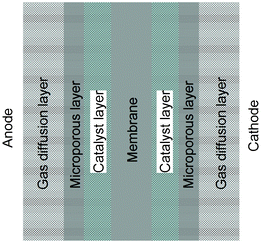 | ||
| Fig. 1 Schematic representation of a membrane electrode assembly (MEA). | ||
Until the 1990s, carbon blacks (CBs) were almost exclusively used as the carbon support for PEMFCs electrodes.7 Great efforts have been made to the development of new carbon nanomaterials with a higher surface area and/or a higher electrical conductivity and explore their feasibility as a carbon material for PEMFCs. These new carbon materials are different from CBs at the nanoscopic level in terms of their structural conformation (e.g. nanotubes), pore texture (e.g. mesopore carbons) and/or, at the macroscopic level, in terms of their form (e.g. microspheres). It is generally believed that metal catalysts should be deposited on porous nanostructured materials in order to increase the specific surface area and better facilitate the mass transport of both chemical and ionic species.7 Three types of pores—micropores <2 nm in diameter, mesopores 2–50 nm in diameter, and macropores >50 nm in diameter—have been identified.20 In conventional carbon materials, micropores provide the greatest contribution to surface area due to their high surface area-to-volume ratio, whereas macropores contribute the least. However, macropores allow for more efficient mass transport than micropores. Thus, mesopores are typically preferred because they balance these two effects, providing high surface area and allowing for efficient mass transport.
Mesoporous carbon (MC) can be classified into two categories according to its structure and morphology:21 i) ordered mesoporous carbon (OMC), which is usually synthesized by nanocasting ordered mesoporous silica (OMS) templates or by directly templating triblock copolymer structure-directing species, and ii) disordered mesoporous carbon (DOMC) with irregular pore structures. Although DOMC shows mesoporosity, the mesopores are, in most cases, isolated or irregularly interconnected. Thus, OMC is preferred as the catalyst support for its higher specific surface area, electricalal conductivity, and mass transport. DOMC may, however, have advantages in the MPL in two-phase mass transport. The present review is focused on recent advances in MC and its fuel cell applications in both the GDL and the CL. This may help us obtain a better understanding of the multifunctional role of MCs and improve the fuel cell performance by taking advantage of the unique properties of MCs.
2 Mesoporous carbon in the gas diffusion layer
The GDL was developed to manage water as well as to promote gas distribution to the active catalyst regions in an attempt to obtain higher power density in all current density regions.22–24 For several years, carbon papers or carbon cloth substrates (macroporous layers) with a polytetrafluoroethylene (PTFE)-based MPL were the major choice for GDLs. The MPL properties, especially porosity and pore size distribution, have an important impact on the mass transport.4,24,25 The most widely used materials for the MPL are Vulcan carbon XC-72R (VC-72), pearl black, acetylene black and Ketjen black. Chun et al.26 modified the pore size distribution of the MPLs using pore forming agents to facilitate cathode mass transport for PEMFC under different humidity conditions. Jordan et al.27 found experimentally that the GDL using acetylene black carbon powder performs better than that using VC-72 carbon powder, because the acetylene black carbon has less micropores than VC-72. The GDL using acetylene black carbon powder promotes gas diffusion. The cell performance increases by 15% when acetylene black carbon is used instead of VC-72 carbon. Wang et al.28 reported a bifunctional GDL with a composite carbon powder consisting of black pearls 2000 and acetylene black carbon. Black pearls 2000 can offer more hydrophilic micropores for liquid transport. Acetylene black carbon possesses comparatively more hydrophobic mesopores, which offers a great many passageways for gas diffusion. By adopting the two carbon blacks with greatly different features, the bifunctional pore structure is able to meet the requirement for good transportation of both gas and liquid water.Since the reactant distribution and proper water management in PEMFCs strongly depend on the porous structure of carbon materials in a GDL layer, it is interesting to learn about this behavior as a function of pore structure. Sahu et al.29 prepared a MC by the co-assembly of a tri-block copolymer, pluronic-F127, as a structure-directing agent, and a mixture of phloroglucinol and formaldehyde as the carbon precursor. The resulting MC showed disordered mesopores with a specific surface area of 370 m2 g−1, a pore diameter of 6.7 nm and a pore volume of 0.45 cm3 g−1. A peak power density of 0.53 W cm−2 at a current density of 1.1 A cm−2 was achieved for the PEMFC employing electrodes with GDLs made of acid treated MC; the PEMFC employing electrodes with GDLs made of commercial VC-72 achieved a peak power density of 0.47 W cm−2 at a current density of 0.93 A cm−2. These PEMFCs were operating at 70 °C with H2 and air feeds at atmospheric pressure. The favorable surface area and pore size distribution of the mesoporous GDL help ameliorate the liquid water flux through the GDL with minimum flooding and improve oxygen diffusion to the catalyst layer during the fuel cell operation. Xing et al.30 compared the performance of a DOMC-based and a VC-72-based anode GDL for a direct dimethyl ether fuel cell (DDFC). The major differences between MC-based and VC-72-based GDLs are the BET surface area, the pore volume, and the pore size distribution (data shown in Fig. 2a). The MC-based GDL provides more passageways for mass transport than the VC-72-based one. The MC-based GDL possesses small hydrophilic and medium hydrophobic pores, which benefit the liquid and gas transport simultaneously. From Fig. 2b, it can be observed the DDFC showed a 20% increase in power density by using the DOMC-based GDL. The electrochemical measurements indicate that the promotion of the anode two-phase mass transport is the main reason for the significant improvement of the DDFC performance.
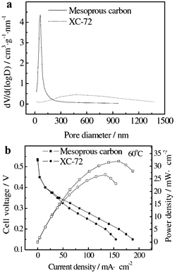 | ||
| Fig. 2 Pore size distribution curves of different GDLs (a); the polarization curves and the power density curves of MEAs with different GDLs (b).30 | ||
From the viewpoint of pore structure and pore-size distribution, MCs are highly desired for facile mass transport in PEMFCs. Combining the best components for each of the functionalities cannot make the best GDL; a trade-off between the properties will give the optimum GDL. Hence, the development of a highly functionalized GDL with self-adjusting water retention and water draining characteristics, along with the ability to transport reactant gases steadily will be essential for the mass utilization of fuel cells in various power density applications.
3 Mesoporous carbon in the catalyst layer
As a catalyst support for fuel cell applications, carbon materials should satisfy several requirements such as a large surface area for finely dispersing catalytic metal particles, high electrical conductivity for providing electrical pathways, highly developed mesoporosity for facile diffusion of reactants and by-products, and electrochemical stability for long term operation. The most commonly used carbon catalyst support material for PEMFCs is VC-72, which has a pore size distribution that is predominantly microporous (<2 nm in pore diameter). As these pores are too small to accommodate Pt nanoparticles of the optimal size (∼3 nm),31–33 the nanoparticles reside primarily on the external surface of VC-72, making it vulnerable to agglomeration and dislodgement. VC-72 is also susceptible to corrosion, forming CO2 during PEMFC operation. In addition, the dominant microporous structure of the VC-72 could restrict the optimal distribution of reactants at the solid-liquid-gas interface of the electrode. Compared with VC-72, MCs have higher surface areas and lower amounts or even an absence of micropores in general. In an MC-supported catalyst, the metal catalyst particles are distributed and supported on the surface or in the pores of the MC. This gives rise to a high dispersion of metal particles, resulting in a large effective surface area of catalyst with a high catalytic activity. The mesoporous structure facilitates smooth mass transport to give rise to high limiting currents. In addition, oxidation-resistant graphitic MCs with strong catalyst-support interactions are expected to provide a substantial improvement in stability and durability to a fuel cell catalyst.3.1 Mesoporous carbon supports
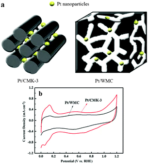 | ||
| Fig. 3 (a) Pore morphology of carbon support on the dispersion of Pt nanoparticles, and (b) cyclic voltammetry curves of the catalysts in 0.5 mol H2SO4 with a scan rate of 20 mV s−1.44 | ||
Evidently, OMCs have shown attractive properties as catalyst supports for increasing cell performance by providing improved catalyst activity and mass transport. This unique property in mass transport is more pronounced when a fuel composed of bigger molecules used.44,50,51 He and coworkers51 investigated the methanol, ethanol and isopropanol oxidation reactions on two Pt catalysts supported on OMCs (CMK-3 and FDU-15Pt). CMK-3 has continuous mesopores between adjacent carbon nanorods which are isolated and hexagonally arrayed by carbon spacers, while FDU-15 has isolated and hexagonally arrayed channel-like mesopores among the continuous carbon framework. The interconnected nanopore structure allows CMK-3 to provide fast mass transfer paths, and in this way enhances the activity of Pt nanoparticles towards alcohol electrooxidation, especially in the case of isopropanol with a bigger molecular size and lower molecular polarity. In addition, the improvement in the mass transfer of MC means that a more concentrated fuel solution can be used to increase the energy density.52
The first report in the literature regarding the use of OMC-supported Pt nanoparticles as oxygen reduction reaction (ORR) catalysts was quite promising.9 In that report, a general strategy for the synthesis of highly ordered, rigid arrays of nanoporous carbon having uniform but tunable diameters was described. These structures were formed by using ordered mesoporous silicas as templates, the removal of which leaves a partially ordered graphitic framework, and the X-ray diffraction pattern (XRD) indicated the hexagonal order between carbon cylinders (TEM image and XRD shown in Fig. 4a and 4b). Compared with commercial carbon-supported catalysts, the resulting OMC-supported Pt catalyst (TEM image shown in Fig. 4c) demonstrated increased catalytic activity and cell efficiency due to the high dispersion of small Pt nanoparticles (ORR test shown in Fig. 4d). The same situation was also reported by Yi and co-authors.53 In addition to the dispersion effect, Yi et al. also investigated the mesoporosity effect of the MC-supported Pt catalysts by changing the molar ratio of the silica template to a formaldehyde–resorcinol resin precursor. Fig. 5 shows that the MC supported Pt catalysts give a higher cell performance then Pt/C does. The result indicated that the surface area combined with the mesoporosity had a positive influence on the metal dispersion and the distribution of ionomers, leading to the enhanced cell performance. In Pei's work,54 the wall thickness effect of the MC was investigated for ORR using two MCs 15 nm (CIC-15) and 26 nm (CIC-26) in pore diameter. Results indicated that both MCs out-performed VC-72. Pt/CIC-15 demonstrated higher ORR activity than Pt/CIC-26, because CIC-15 has significantly thicker walls, giving a lower measured electronic resistance, a lower ORR Tafel slope, and thus better performance overall despite the smaller pore size and lower surface area. In Joo's work,55 the pore diameter effect of the MC (15, 25 and 40 nm) was also investigated for ORR in PEMFCs. They found that all MC-supported Pt catalysts exhibited higher cell performance than a catalyst supported on activated carbon. In particular, the Pt/MC-40 nm catalyst showed the best cell performance among the catalysts tested. They indicated that the large pore size and the high surface roughness of MC-40 nm favored Pt dispersion. In addition, they also pointed out that the large pore size of the Pt/MC-40 nm appeared to have a positive effect on the distribution of ionomers, resulting in the facile formation of a triple-phase boundary. In their work, the electronic resistances of the three MCs were nearly the same. Compared with Pei and Joo's respective works, the conflicting electronic resistance of the MC-supported Pt catalysts may have been due to the morphological difference between the MC and different Pt loadings on carbon support. In Banham's work,56 the pore size, wall thickness and wall crystallinity of carbon materials were compared in VC-72, OMCs (a surfactant-templated OMC with 1.6 and 3.3 nm pores), silica colloid-imprinted carbon (CIC with a 15 nm in pore size) supported Pt catalysts. TEM measurements revealed that the Pt nanoparticles resided inside the majority of the pores of the OMCs and CIC, but are located only on the outer-surface of VC-72. ORR performance studies showed that the Pt-loaded CIC outperformed both Pt-loaded OMCs and VC-72 due to the higher electronic conductivity (thicker and more crystalline walls) and facilitated mass transport in the larger pores of the CIC support. In Joo's work,57 the effect of the particle size of the OMCs on the electrocatalytic activity of Pt/OMC catalysts was investigated for ORR in DMFCs. For this purpose, OMS templates with three distinct particle sizes (100, 300, 700 nm) were synthesized by controlling the synthesis pH and Na content in the sodium silicate solution. In ORR activity measurements, marginal differences were observed for the three OMC-supported Pt catalysts. The particle sizes of OMC, which are in most cases dependent on the size of the OMS template, ranged from 100 nm to several microns. For fuel cell applications, similar to other areas, smaller particle sizes are favored for the efficient diffusion and transport of reactants and byproducts. Furthermore, each primary particle should be sufficiently separated to avoid significant agglomeration.
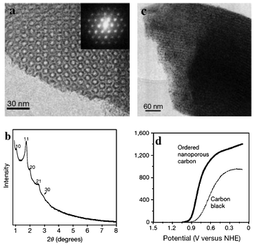 | ||
Fig. 4 (a) TEM image viewed along the direction of the OMC and the corresponding Fourier diffractogram, (b) XRD pattern of the OMC, (c) TEM image of the OMC supported Pt, (d) ORR test for 33 wt% Pt/carbons, obtained in 0.1 M HClO4 saturated with O2 at 10![[thin space (1/6-em)]](https://www.rsc.org/images/entities/char_2009.gif) 000 rpm with a scan rate of 50 mV s−1.9 000 rpm with a scan rate of 50 mV s−1.9 | ||
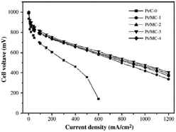 | ||
| Fig. 5 Cell performance of the carbon supported Pt catalysts, cell temperature 75 °C (MC-X, X represents the molar ratio of silica to carbon precursor).53 | ||
Studies have indicated that the mesopores of a carbon support are favored for mass transfer of liquid and gas reactants and products in electrochemical reactions of fuel cells, although this is still controversial. Su and co-workers58 pointed out that the mesoporous structure of the carbon support is important for liquid-phase electrochemical reactions, while micropores are more suitable for gas reactions at the electrodes of fuel cells. In their work, the Pt catalysts supported on mesoporous and microporous carbons were compared as both MOR and ORR catalysts in DMFCs. OMCs synthesized using the template method were employed as the representative of MC, and carbon black BP2000 was used as the microporous carbon because of its microporous structure and high surface area comparable to that of the prepared OMCs. The results showed that, for MOR, the Pt/OMC catalyst possessed a significantly higher catalytic activity measured by cyclic voltammetry than Pt/BP2000 and its performance even exceeded that of commercial catalyst Pt/C (E-TEK). The electrochemical impedance measurement indicated that Pt/OMC had a smaller charge-transfer resistance and faster overall MOR rate than either the Pt/BP2000 or E-TEK catalyst. In contrast, for ORR, the mass activity of Pt/BP2000 was higher than that of Pt/OMC on a rotating disk electrode but was comparable to that of E-TEK. In addition to the reactant and product transport issue, Ambrosio59 and Liu60 indicated that further investigation is needed to improve the ohmic resistance limitation of MC materials. In particular, the variation of the grain size distribution with the Pt content and the effective distribution of ionomers such as Nafion® on the OMC surface should be considered.
Gupta et al.68 investigated the stability of the MC-supported Pt nanoparticles (<4 nm) in ORR. The result indicated that the graphitic MC-supported Pt showed negligible loss in mass activity and active surface area after an accelerated durability test (1000 cycles, 0.5–1.2 V), whereas the Pt catalyst supported on amorphous MC lost −70% of its mass activity and active surface area. The high oxidation resistance of the graphitized carbon helped to maintain electrical contact between the metal and carbon while mitigating Pt dissolution, ripening, and coalescence. Improvement in catalyst stability provided by MC support was also reported by Liu,69 Slanac70 and Shao.71 In addition, Gupta et al.68 pointed out that the high dispersion of Pt on mesoporous supports with large surface areas and tortuous pathways in the bicontinuous 3D mesopores can further lower the tendency of Pt to coalesce, contributing to the catalyst stability.
3.2 N-doped mesoporous carbon catalysts
Nitrogen doping of carbon nanostructured materials can be classified into two categories:72 (i) direct doping during the synthesis of porous carbon nanostructured materials, known as ‘‘in situ’’ doping; and (ii) post-treatment of presynthesized carbon nanostructured materials with nitrogen-containing precursors (N2, NH3, etc.), known as post-doping. Post-doping of carbon nanomaterials often leads to surface functionalization without altering their bulk properties. In contrast, in situ doping can incorporate nitrogen atoms into the entire carbon nanomaterial homogeneously.Wang et al.73 demonstrated that nitrogen-doped OMCs via NH3 activation can act as alternative metal-free ORR catalysts with a better stability than Pt-based electrocatalysts. However, the catalytic performance of these reported N-doped carbon nanomaterials still needs to be further improved to meet the requirements of practical applications in acidic media. Liu et al.74 reported the in situ fabrication of N-doped OMC arrays on the basis of a metal-free nanocasting technology using ordered mesoporous silica SBA-15 as a template, and a nitrogen-containing aromatic dyestuff, N,N′-bis(2,6-diisopropyphenyl)-3,4,9,10-perylenetetracarboxylic diimide, as the carbon precursor. The unique features of the resulting N-OMC arrays, including a high surface area and a graphitic framework with moderate nitrogen content, led to high electrocatalytic activity, excellent long-term stability, and resistance to methanol crossover effects in the ORR in alkaline media. These properties are superior to those observed for the commercially available Pt/C catalyst. Owing to the metal-free preparation procedure, the electrocatalytic activity can be attributed exclusively to the incorporation of nitrogen in N-OMC arrays. Using SBA-15 as the template and polypyrrole as the nitrogen-containing precursor, Shrestha et al.75 prepared N-OMCs and investigated the ORR activity in acidic media. The N-OMC prepared at 800 °C showed enhanced catalytic activity and stability over VC-72.
An overview of the known and possible nitrogen functionalities present in carbon is shown in Fig. 6. The nitrogen functionalities are in the forms of pyridinic-N, pyrrolic-N/pyridone-N, quaternary-N (graphite-N), and pyridinic-N+–O− (oxide).75,76 It was reported that pyridinic-N is a type of nitrogen that contributes one p-electron to the aromatic p-system and has a lone electron pair in the plane of the carbon matrix.76 The pyridinic-N can be found on the edge of a carbon plane and a carbon vacancy. The lone electron pair in the plane of the carbon matrix enhances the electrondonor property of the catalyst, weakening the O–O bond via the bonding between oxygen and nitrogen and/or the adjacent carbon atom, and facilitating the reduction of oxygen.77,78 Matter et al.17,79 proposed that these pyridinic-N moieties may not be the definitive ORR active sites, but based on their research results, the more active samples contain more pyridinic-N. Note that the relationship between the chemical state of nitrogen and the ORR activity of carbon-based catalysts has long been a topic of debate. Liu et al.74 indicated that graphite-like nitrogen atoms in N-OMGs arrays play a crucial role in ORR in alkaline media. Yang et al.80 also reported that the local graphitic carbon structure of N-doped MCs results in high catalytic activity, even in the metal-free case in ORR in alkaline media. The as-prepared materials exhibit a low onset potential for ORR (Fig. 7A) and methanol tolerance (Fig. 7D) compared with those of commercial 20 wt% Pt/C catalyst. Analysis of the plateau currents through Koutecky–Levich plots (Fig. 7B) reveals the reduction of O2 with meso-EmU catalysts by a four-electron process (Fig. 7C), yielding water as the main product. Liu and co-authors17 suggested that pyridinic-N and quaternary-N may both be the active sites for ORR and the change of pyridinic-N to pyridinic-N–H may decrease the ORR activity in N-OMCs. Ikeda et al.81 used the Car–Parrinello MD approach to model oxygen reduction on N-doped carbon layers and found that the O2 molecule is preferentially adsorbed associatively at C sites on graphene-like zig-zag edges if a quaternary-N is located nearby. The subsequent oxygen reduction mainly takes the four-electron reaction path, with a low free-energy barrier. However, recent studies have suggested that the edge plane defects are important factors for enhancing electrocatalysis in ORR. However, the role of nitrogen in ORR activity remains to be elucidated. The term “edge plane” or “defects” which indicates the active site is somewhat ambiguous.78,82 Therefore, the exact catalytic role of each of the nitrogen forms in nanocarbon ORR catalysts is still a matter of controversy.73,83 In addition, it is a challenge to determine the exact locations of nitrogen atoms in the nanocarbon structures, the chemical nature of the catalytic sites, or the electrochemical kinetics of the N-doped nanocarbon electrodes. A combined experimental and theoretical approach would be essential in studying the N-doped nanocarbon catalysts.78
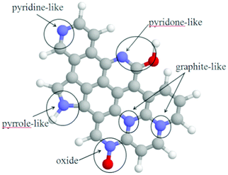 | ||
| Fig. 6 Local geometry for various nitrogens in graphite. Gray, blue, red, and white balls represent carbon, nitrogen, oxygen, and hydrogen atoms, respectively. | ||
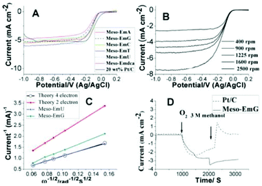 | ||
| Fig. 7 (A) Polarization curves on a glassy carbon rotating disk electrode for N-doped carbons, as compared with 20 wt% Pt/C in O2-saturated 0.1 M KOH at a scan rate of 10 mV s−1 and rotation rate of 1600 rpm. (B) Voltamperograms for oxygen reduction on a meso-EmG electrode in O2-saturated 0.1 M KOH at various rotation speeds; scan rate 10 mV s−1. (C) Koutecky–Levich plot of meso-EmU at −0.35 V, (D) Current–time (I–t) response of meso-EmG and 20 wt% Pt/C at 0.26 V in 0.1 M KOH saturated with N2 (0–1000 s) or O2 (1000–2000 s) and in O2-saturated 3 M CH3OH (2000–3000 s).80 | ||
Although N-doping has greatly improved ORR activity, these metal-free catalysts still exhibited poorer, or at best comparable, ORR performance compared with Pt catalysts.73,74,84 Work to improve oxygen reduction in fuel cells is ongoing. Recently, Liu and co-workers17 investigated the Fe–N-MC ORR catalysts by pyrolyzing iron acetate-impregnated N-MC in argon, where the N-doped ordered porous carbon was synthesized via a nano-casting process using polyacrylonitrile as the carbon and nitrogen precursors and mesoporous silica as a hard template. They found that the encapsulated Fe species in the carbon substrate may exert some electron effect on the nitrogen-modified active sites and facilitate the ORR, but these were not active sites. They also found that the incorporation of iron during catalyst preparation produced more ORR active sites which can catalyze the four-electron reaction of ORR in acidic media. They indicated that the presence of Fe may facilitate the incorporation of pyridinic-N and quaternary-N into the carbon matrix with a strong Lewis basicity, which can enhance the electron-donor properties of the N-doped carbon. This in turn will weaken the O–O bond via the bonding between oxygen and nitrogen and/or the adjacent carbon atom. Hence, the catalytic activity of the N-doped carbon-based catalysts will increase in the ORR. Lefevre and Matter proposed that the transition metal may catalyze the formation of active sites through the growth of carbon nanostructures with a specific architecture. For example, Fe particles might catalyze the growth of carbon nanostructures with a higher percentage of the edge plane exposure.85,86 These edge planes were believed to exhibit much higher activity towards ORR. However, there is much disagreement in the literature regarding the nature of the active sites in ORR. In order to understand the structure of the active sites more clearly, more sensitive and efficient surface characterization should be undertaken. It should be mentioned that the N-OMCs were also more desirable as catalyst supports than pristine MC. Studies have indicated that the presence of doped nitrogen species in carbon supports favors Pt dispersion and leads to the increased catalyst activity and stability of the resulting catalysts.87–89 The improvements in methanol-tolerance ORR catalysts were also reported by Liu and co-workers with the data shown in Fig. 8.90
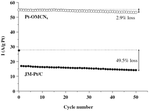 | ||
| Fig. 8 Durability tests of Pt-OMCNx and JM-Pt/C during 50 cycles of ORR in O2 saturated 0.1 M H2SO4 solution with 1 M CH3OH. The dashed line indicates the current density of Pt-OMCNx and JM-Pt/C performed during ORR in O2 saturated 0.1 M H2SO4 solution without CH3OH.90 | ||
4 Conclusions and outlook
The overall performance of PEMFCs is controlled by different processes, such as the diffusion of the fuel to the electrolyte–catalyst interface, the electrochemical reaction at the catalyst–electrolyte interface, the transport of charges by the current collector, the ion transport across the membrane, the hydration of the electrolyte membrane, etc.91 As mentioned earlier, MCs have demonstrated great performance as a constituent of the gas diffusion layer and the catalyst layer, among other PEMFC components. The incorporation of the DOMC into the GDL improves the two-phase mass transport in PEMFCs. The replacement of carbon black support by OMCs leads to significant changes in the catalyst layer structure of the fuel cell. The high surface area and large amount of mesopores in OMCs allow high metal dispersion and good reactant flux. Thus, in most cases, catalysts supported on OMCs have higher catalytic activity than the same catalysts supported on carbon black. There are some discrepancies between the reported results, because the properties of MC-supported catalysts depend on several factors such as the primary particle size, pore structure and crystallinity of the OMC as well as the preparation method. By increasing the graphitization of the MCs, the stability of the fuel cell conditions of MC-supported metals can be enhanced. The unique features of N-OMCs, including a high surface area and a graphitic framework with moderate nitrogen content, leads to high electrocatalytic activity, excellent long term stability, and resistance to fuel crossover effects.Even though MCs have been proved to be valuable in improving the PEMFC performance, a few challenges still need to be overcome before they can be used widely in PEMFCs. The OMC with a smaller (<100 nm) primary particle size but wider pore size (>10 nm) and 3D interconnected pore structures is a more favorable catalyst support. In fact, the Nafion® binder solution, which is generally used in electrode preparation, is made up of ionomers that cannot enter pores smaller than 20 nm in diameter, so catalyst particles chemically deposited into such pores are not in contact with the proton conductor and/or the fuel. For this reason, the presence of mesopores with pore size <20 nm supports the gas flow, but decreases the active surface area of the catalyst. For fuel cells, a method should be developed for preparing metal (Pt or Pt/Ru) nanocatalysts using OMCs as the support with a high loading level while maintaining the particle size below 3 nm. Although the scope of the present review is limited to fuel cells, the application of MCs in other electrochemical energy devices such as Li-ion batteries and electric double layer capacitors (EDLCs) is also promising. The enhanced performance of electrochemical energy devices that make use of MC materials demonstrates the promise of such materials, which are likely be commercialized in the near future.
Acknowledgements
The work described in this paper was fully supported by a grant from the Research Grants Council of the Hong Kong Special Administrative Region, China (Project No. HKUST9/CRF/11G).References
- Y. Wang, K. S. Chen, J. Mishler, S. C. Cho and X. C. Adroher, Appl. Energy, 2011, 88, 981–1007 CrossRef CAS.
- W. Schmittinger and A. Vahidi, J. Power Sources, 2008, 180, 1–14 CrossRef CAS.
- T. S. Zhao, C. Xu, R. Chen and W. W. Yang, Prog. Energy Combust. Sci., 2009, 35, 275–292 CrossRef CAS.
- L. Cindrella, A. M. Kannan, J. F. Lin, K. Saminathan, Y. Ho, C. W. Lin and J. Wertz, J. Power Sources, 2009, 194, 146–160 CrossRef CAS.
- Y. S. Li, T. S. Zhao and W. W. Yang, Int. J. Hydrogen Energy, 35, 5656–5665 CrossRef CAS.
- Q. X. Wu, S. Y. Shen, Y. L. He and T. S. Zhao, Int. J. Hydrogen Energy, 2012, 37, 5958–5968 CrossRef CAS.
- E. Antolini, Appl. Catal., A, 2009, 88, 1–24 CrossRef CAS.
- J. B. Xu and T. S. Zhao, J. Power Sources, 2010, 195, 1071–1075 CrossRef CAS.
- S. H. Joo, S. J. Choi, I. Oh, J. Kwak, Z. Liu, O. Terasaki and R. Ryoo, Nature, 2001, 412, 169–172 CrossRef CAS.
- Y. Sun, Q. Wu and G. Shi, Energy Environ. Sci., 2011, 4, 1113–1132 CAS.
- Y. Zhou, K. Neyerlin, T. S. Olson, S. Pylypenko, J. Bult, H. N. Dinh, T. Gennett, Z. Shao and R. O'Hayre, Energy Environ. Sci., 2010, 3, 1437–1446 CAS.
- J. H. Jang, J. Kim, Y. H. Lee, I. Y. Kim, M. H. Park, C. W. Yang, S. J. Hwang and Y. U. Kwon, Energy Environ. Sci., 2011, 4, 4947–4953 CAS.
- E. F. Holby, W. Sheng, Y. Shao-Horn and D. Morgan, Energy Environ. Sci., 2009, 2, 865–871 CAS.
- V. Mazumder, Y. Lee and S. Sun, Adv. Funct. Mater., 2010, 20, 1224–1231 CrossRef CAS.
- Z. X. Liang, T. S. Zhao and J. B. Xu, J. Power Sources, 2008, 185, 166–170 CrossRef CAS.
- J. Xu, T. Zhao, Z. Liang and L. Zhu, Chem. Mater., 2008, 20, 1688–1690 CrossRef CAS.
- G. Liu, X. Li, P. Ganesan and B. N. Popov, Appl. Catal., B, 2009, 93, 156–165 CrossRef CAS.
- R. Chen and T. S. Zhao, Electrochem. Commun., 2007, 9, 718–724 CrossRef CAS.
- F. Jaouen, E. Proietti, M. Lefevre, R. Chenitz, J. P. Dodelet, G. Wu, H. T. Chung, C. M. Johnston and P. Zelenay, Energy Environ. Sci., 2011, 4, 114–130 CAS.
- E. P. Ambrosio, C. Francia, C. Gerbaldi, N. Penazzi, P. Spinelli, M. Manzoli and G. Ghiotti, J. Appl. Electrochem., 2008, 38, 1019–1027 CrossRef CAS.
- J. Lee, J. Kim and T. Hyeon, Adv. Mater., 2006, 18, 2073–2094 CrossRef CAS.
- Q. X. Wu, T. S. Zhao and W. W. Yang, Int. J. Heat Mass Transfer, 2010, 54, 1132–1143 CrossRef.
- Y. S. Li, T. S. Zhao, J. B. Xu, S. Y. Shen and W. W. Yang, J. Power Sources, 2011, 196, 1802–1807 CrossRef CAS.
- C. Xu, T. S. Zhao and Y. L. He, J. Power Sources, 2007, 171, 268–274 CrossRef CAS.
- P. P. Mukherjee, Q. Kang and C. Y. Wang, Energy Environ. Sci., 2011, 4, 346–369 CAS.
- J. H. Chun, K. T. Park, D. H. Jo, J. Y. Lee, S. G. Kim, E. S. Lee, J. Y. Jyoung and S. H. Kim, Int. J. Hydrogen Energy, 2010, 35, 11148–11153 CrossRef CAS.
- L. R. Jordan, A. K. Shukla, T. Behrsing, N. R. Avery, B. C. Muddle and M. Forsyth, J. Appl. Electrochem., 2000, 30, 641–646 CrossRef CAS.
- X. Wang, H. Zhang, J. Zhang, H. Xu, X. Zhu, J. Chen and B. Yi, J. Power Sources, 2006, 162, 474–479 CrossRef CAS.
- A. K. Sahu, K. G. Nishanth, G. Selvarani, P. Sridhar, S. Pitchumani and A. K. Shukla, Carbon, 2009, 47, 102–108 CrossRef CAS.
- L. H. Xing, Y. Z. Gao, Z. B. Wang, C. Y. Du and G. P. Yin, Int. J. Hydrogen Energy, 2011, 36, 11102–11107 CrossRef CAS.
- D. Zhao and B. Q. Xu, Angew. Chem., Int. Ed., 2006, 45, 4955–4959 CrossRef CAS.
- H. Bönnemann and Ryan M. Richards, Eur. J. Inorg. Chem., 2001, 2001, 2455–2480 CrossRef.
- Z. Tang, D. Geng and G. Lu, J. Colloid Interface Sci., 2005, 287, 159–166 CrossRef CAS.
- Z. Wu, Y. Lv, Y. Xia, P. A. Webley and D. Zhao, J. Am. Chem. Soc., 2012, 134, 2236–2245 CrossRef CAS.
- G. S. Chai, S. B. Yoon, J. S. Yu, J. H. Choi and Y. E. Sung, J. Phys. Chem. B, 2004, 108, 7074–7079 CrossRef CAS.
- H. Chang, S. H. Joo and C. Pak, J. Mater. Chem., 2007, 17, 3078–3088 RSC.
- J. Qi, L. Jiang, Q. Tang, S. Zhu, S. Wang, B. Yi and G. Sun, Carbon, 2012, 50, 2824–2831 CrossRef CAS.
- G. Ramos-Sanchez, M. M. Bruno, Y. R. J. Thomas, H. R. Corti and O. Solorza-Feria, Int. J. Hydrogen Energy, 2012, 37, 31–40 CrossRef CAS.
- A. D. Moore, S. M. Holmes and E. P. L. Roberts, RSC Adv., 2012, 2, 1669–1674 RSC.
- T. Maiyalagan, T. O. Alaje and K. Scott, J. Phys. Chem. C, 2012, 116, 2630–2638 CAS.
- Y. Ma, L. Cui, J. He, T. Wang, Y. Guo, J. Tang, G. Li, Y. Hu, H. Xue, M. Liu and X. Sun, Electrochim. Acta, 2012, 63, 318–322 CrossRef CAS.
- F. Hasche, T. P. Fellinger, M. Oezaslan, J. P. Paraknowitsch, M. Antonietti and P. Strasser, ChemCatChem, 2012, 4, 479–483 CrossRef CAS.
- B. Guvenatam, B. Ficclar, A. Bayrakceken and I. Eroglu, Int. J. Hydrogen Energy, 2012, 37, 1865–1874 CrossRef.
- S. Song, Y. Liang, Z. Li, Y. Wang, R. Fu, D. Wu and P. Tsiakaras, Appl. Catal., B, 2010, 98, 132–137 CrossRef CAS.
- Z. P. Sun, X. G. Zhang, Y. Y. Liang, H. Tong, R. L. Xue, S. D. Yang and H. L. Li, J. Electroanal. Chem., 2009, 633, 1–6 CrossRef CAS.
- K. Y. Chan, S. W. Ting and J. Ren, in AIChE 100–2008 AIChE Annual Meeting, Conference Proceedings, 2008 Search PubMed.
- J. R. C. Salgado, F. Alcaide, G. Alvarez, L. Calvillo, M. J. Lazaro and E. Pastor, J. Power Sources, 2010, 195, 4022–4029 CrossRef CAS.
- T. K. Yeh, C. H. Tsai and M. T. Wu, Mater. Chem. Phys., 2009, 114, 199–203 CrossRef CAS.
- H. J. Liu, X. M. Wang, W. J. Cui, Y. Q. Dou, D. Y. Zhao and Y. Y. Xia, J. Mater. Chem., 20, 4223–4230 RSC.
- J. Liu, Z. Li, C. He, R. Fu, D. Wu and S. Song, Int. J. Hydrogen Energy, 2011, 36, 2250–2257 CrossRef CAS.
- C. He, Y. Liang, R. Fu, D. Wu, S. Song and R. Cai, J. Mater. Chem., 2011, 21, 16357–16364 RSC.
- Z. Yan, H. Meng, L. Shi, Z. Li and P. K. Shen, Electrochem. Commun., 2010, 12, 689–692 CrossRef CAS.
- J. B. Joo, P. Kim, W. Kim, J. Kim and J. Yi, Catal. Today, 2006, 111, 171–175 CrossRef CAS.
- K. Pei, D. Banham, F. Feng, T. Furstenhaupt, S. Ye and V. Birss, Electrochem. Commun., 12, 1666–1669 CrossRef CAS.
- J. B. Joo, P. Kim, W. Kim and J. Yi, J. Electroceram., 2006, 17, 713–718 CrossRef CAS.
- D. Banham, F. Feng, T. Furstenhaupt, K. Pei, S. Ye and V. Birss, J. Power Sources, 2011, 196, 5438–5445 CrossRef CAS.
- S. H. Joo, H. I. Lee, D. J. You, K. Kwon, J. H. Kim, Y. S. Choi, M. Kang, J. M. Kim, C. Pak, H. Chang and D. Seung, Carbon, 2008, 46, 2034–2045 CrossRef CAS.
- F. Su, C. K. Poh, Z. Tian, G. Xu, G. Koh, Z. Wang, Z. Liu and J. Lin, Energy Fuels, 24, 3727–3732 CrossRef CAS.
- E. P. Ambrosio, M. A. Dumitrescu, C. Francia, C. Gerbaldi and P. Spinelli, Fuel Cells, 2009, 9, 197–200 CrossRef CAS.
- B. Liu and S. Creager, Electrochim. Acta, 55, 2721–2726 CrossRef CAS.
- J. B. Xu, T. S. Zhao, S. Y. Shen and Y. S. Li, Int. J. Hydrogen Energy, 2010, 35, 6490–6500 CrossRef CAS.
- H. Liu and A. Manthiram, Energy Environ. Sci., 2009, 2, 124–132 CAS.
- L. Zhang, L. Wang, C. M. B. Holt, B. Zahiri, Z. Li, K. Malek, T. Navessin, M. H. Eikerling and D. Mitlin, Energy Environ. Sci., 2012, 5, 6156–6172 CAS.
- J. Zhang, K. Sasaki, E. Sutter and R. R. Adzic, Science, 2007, 315, 220–222 CrossRef CAS.
- T. Okada, Y. Ayato, H. Satou, M. Yuasa and I. Sekine, J. Phys. Chem. B, 2001, 105, 6980–6986 CrossRef CAS.
- Y. Shao, G. Yin and Y. Gao, J. Power Sources, 2007, 171, 558–566 CrossRef CAS.
- G. Gupta, D. A. Slanac, P. Kumar, J. D. Wiggins-Camacho, X. Wang, S. Swinnea, K. L. More, S. Dai, K. J. Stevenson and K. P. Johnston, Chem. Mater., 2009, 21, 4515–4526 CrossRef CAS.
- G. Gupta, D. A. Slanac, P. Kumar, J. D. Wiggins-Camacho, J. Kim, R. Ryoo, K. J. Stevenson and K. P. Johnston, J. Phys. Chem. C, 2010, 114, 10796–10805 CAS.
- S. H. Liu, W. Y. Yu, C. H. Chen, A. Y. Lo, B. J. Hwang, S. H. Chien and S. B. Liu, Chem. Mater., 2008, 20, 1622–1628 CrossRef CAS.
- D. A. Slanac, N. Li, K. J. Stevenson and K. P. Johnston, in 10AIChE–2010 AIChE Spring Meeting and 6th Global Congress on Process Safety Search PubMed.
- Y. Shao, S. Zhang, R. Kou, X. Wang, C. Wang, S. Dai, V. Viswanathan, J. Liu, Y. Wang and Y. Lin, J. Power Sources, 2010, 195, 1805–1811 CrossRef CAS.
- Y. Shao, J. Sui, G. Yin and Y. Gao, Appl. Catal., B, 2008, 79, 89–99 CrossRef CAS.
- X. Wang, J. S. Lee, Q. Zhu, J. Liu, Y. Wang and S. Dai, Chem. Mater., 2010, 22, 2178–2180 CrossRef CAS.
- R. Liu, D. Wu, X. Feng and K. Müllen, Angew. Chem., Int. Ed., 2010, 49, 2565–2569 CrossRef CAS.
- S. Shrestha and W. E. Mustain, J. Electrochem. Soc., 2010, 157, B1665–B1672 CrossRef CAS.
- J. R. Pels, F. Kapteijn, J. A. Moulijn, Q. Zhu and K. M. Thomas, Carbon, 1995, 33, 1641–1653 CrossRef CAS.
- K. Gong, F. Du, Z. Xia, M. Durstock and L. Dai, Science, 2009, 323, 760–764 CrossRef CAS.
- D. Yu, E. Nagelli, F. Du and L. Dai, J. Phys. Chem. Lett., 2010, 1, 2165–2173 CrossRef CAS.
- P. H. Matter, L. Zhang and U. S. Ozkan, J. Catal., 2006, 239, 83–96 CrossRef CAS.
- W. Yang, T. P. Fellinger and M. Antonietti, J. Am. Chem. Soc., 2011, 133, 206–209 CrossRef CAS.
- T. Ikeda, M. Boero, S. F. Huang, K. Terakura, M. Oshima and J. I. Ozaki, J. Phys. Chem. C, 2008, 112, 14706–14709 CAS.
- H. Niwa, K. Horiba, Y. Harada, M. Oshima, T. Ikeda, K. Terakura, J.-I. Ozaki and S. Miyata, J. Power Sources, 2009, 187, 93–97 CrossRef CAS.
- J. I. Ozaki, S. i. Tanifuji, A. Furuichi and K. Yabutsuka, Electrochim. Acta, 2010, 55, 1864–1871 CrossRef CAS.
- K. Kwon, Y. J. Sa, J. Y. Cheon and S. H. Joo, Langmuir, 2012, 28, 991–996 CrossRef CAS.
- M. Lefevre, J. P. Dodelet and P. Bertrand, J. Phys. Chem. B, 2002, 106, 8705–8713 CrossRef CAS.
- P. H. Matter and U. S. Ozkan, Catal. Lett., 2006, 109, 115–123 CrossRef CAS.
- Y. Guo, J. He, T. Wang, H. Xue, Y. Hu, G. Li, J. Tang and X. Sun, J. Power Sources, 2011, 196, 9299–9307 CrossRef CAS.
- G. Ramos-Sanchez, M. M. Bruno, Y. R. J. Thomas, H. R. Corti and O. Solorza-Feria, Int. J. Hydrogen Energy, 2011, 37, 31–40 CrossRef.
- S. H. Liu, S. C. Chen and W. H. Sie, Int. J. Hydrogen Energy, 2011, 36, 15060–15067 CrossRef CAS.
- S. H. Liu and J. R. Wu, Int. J. Hydrogen Energy, 2011, 36, 87–93 CrossRef CAS.
- W. Zhang, S. Ravi and P. Silva, Reviews on Advanced Materials Science, 2011, 29, 1–14 CAS.
| This journal is © The Royal Society of Chemistry 2013 |
