Tunable Fano resonance in symmetric multilayered gold nanoshells
Ovidio
Peña-Rodríguez
*a,
Antonio
Rivera
a,
Mariano
Campoy-Quiles
b and
Umapada
Pal
c
aInstituto de Fusión Nuclear, Universidad Politécnica de Madrid, C/José Gutiérrez Abascal 2, E-28006, Madrid, Spain. E-mail: ovidio.pena@upm.es; Fax: +34 91 336 3002
bInstitut de Ciència de Materials de Barcelona (ICMAB-CSIC), Campus UAB, E-08193, Bellaterra, Spain. E-mail: mcampoy@icmab.es
cInstituto de Física, Benemérita Universidad Autónoma de Puebla, A.P. J-48, Puebla 72570, Mexico. E-mail: upal@sirio.ifuap.buap.mx; Fax: +52 222 229 5611
First published on 1st November 2012
Abstract
We have studied the evolution of dipole–dipole all-plasmonic Fano resonances (FRs) in symmetric multilayered nanoshells as a function of their geometrical parameters. We demonstrate that symmetry breaking is not mandatory for controlling the Fano resonance in such multilayer structures. By carefully selecting the geometrical parameters, the position of the FR can be tuned between 600 and 950 nm and its intensity can be increased up to four fold with respect to the non-optimized structures. Generation of FRs in such symmetric nanostructures presents clear advantages over their asymmetric counterparts, as they are easier to fabricate and can be used in a wider range of technological applications.
Introduction
Fano resonances (FRs) are typical spectral features caused by the coupling of a discrete state with a continuum.1 This phenomenon has been known for many years in atomic physics and constitutes the basis for the electromagnetically induced transparency (EIT);2–6 however, only recently it has been achieved in all-plasmonic systems.7–13 In addition to fundamental scientific interests, plasmonic Fano resonances in strongly coupled systems give rise to the so-called plasmon-induced transparency (PIT),4,14 a phenomenon similar to EIT. In turn, PIT has a great potential for the fabrication of sub-wavelength waveguides, low-loss metamaterials and chemical sensors.6,12–16 Therefore, it is not surprising that several plasmonic structures have been proposed as candidates for generating Fano resonances.Plasmonic nanostructures of appropriate size (50–100 nm) typically exhibit wide dipolar resonance and one or more narrow, higher-order modes that overlap spatially and spectrally to some extent. This situation might be optimal for producing FRs, as the former mode can act as a continuum and the latter as the localized state. However, coupling between the dipolar and higher-order modes is forbidden for concentric systems because they are orthogonal.17,18 Hence, breaking the symmetry of the system is the most common approach for producing Fano resonances in these structures. This symmetry breaking produces a non-uniform electromagnetic environment around the nanoparticle, leading to the effective coupling between broad and narrow plasmon resonances.
For instance, symmetry breaking-induced plasmonic Fano resonances have been reported in a variety of plasmonic systems such as heterodimer structures,7,19,20 nanocavities,11 non-concentric multilayered nanoshells14,18,21 and ring-disk nanocavities,9,22,23 nanoparticle clusters,12,15,16,24 and nanocrystals supported on substrates.25,26 This systematic and controlled symmetry breaking is very complicated to attain experimentally and, consequently, most of these metal nanostructures are either fabricated using complex and expensive techniques or they work only under specific conditions (e.g., for light impinging at certain angles), which severely reduces their application potentials. In contrast, plasmonic Fano resonances in highly symmetric metal NPs are harder to obtain and have been reported only in a few symmetric bimetallic NPs,27,28 metallic nanoshells18 and gold@dielectric core–shell structures.29 Moreover, to the best of our knowledge, the structural tunability of all-plasmonic Fano resonances has never been studied in detail for symmetric nanoshells.
In this work we investigate the plasmon coupling in multilayered and symmetric gold nanoshells (Au/SiO2/Au and SiO2/Au/SiO2/Au).30–32 This kind of structures is both easy to synthesize14,33 and interesting for various applications like cancer treatment,33 medical diagnostics,34 immunoassay35,36 and studies of living cells and bacteria.37 A proper modulation of the geometry reveals the tunable nature of the dipole–dipole Fano resonances in the extinction spectra of these nanoshells. Generation and evolution of the FRs in these multilayered systems are discussed on the basis of plasmon hybridization theory.
Procedure
Among the methods available for studying the scattering of electromagnetic (EM) radiation by small particles, Mie theory38,39 is probably the most popular and widely used one. Though it was originally developed for solid spheres, it has also been extended for bi- and multi-layered spheres.40–42 The analytical solution for the light scattering by a multilayered sphere can be obtained by expressing the electromagnetic field inside each layer of the sphere as a linear combination of inward- and outward-travelling waves. Each layer is characterized by a size parameter xl = 2πnmrl/λ = krl and a relative refractive index ml = nl/nm, l = 1, 2, …, L, where λ is the wavelength of the incident wave in a vacuum, rl is the outer radius of the lth layer, k is the propagation constant and nm and nl are the refractive indices of the medium outside the particle and its lth component, respectively. For an L-layered sphere, there are 2L unknown field coefficients, and the scattering coefficients can be calculated by matching the tangential components of the electromagnetic fields at each interface and solving the obtained linear system of 2L independent equations.43,44The theory of plasmon hybridization45 is a complementary, mainly qualitative method, where the characteristics of the SPR are explained in terms of interactions between the plasmons of metallic nanostructures of simpler shapes. In the present article, we have studied gold multilayered nanoshells with geometries as shown in Fig. 1. The extinction, scattering and absorption efficiencies (Qext, Qsca and Qabs, respectively) for different configurations were calculated using Scattnlay,43 a computer implementation of the algorithm developed by Yang44 for the calculation of the scattering of EM radiation by a multilayered sphere. For calculations, the bulk values of Au dielectric functions reported by Johnson and Christy46 have been utilized, after applying the usual size correction.47,48 The obtained shifts of the SPR positions were explained in terms of the plasmon hybridization theory.
![(a) Schematic illustration of a double concentric nanoshell and its corresponding energy diagram, representing plasmon hybridization. The extinction spectra (b) of the inner nanoshell with [t0, t1] = [25, 10] nm, (c) the multilayered configuration with [t0, t1, t2, t3] = [25, 10, 15, 25] nm, and (d) the outer nanoshell with [t0, t1] = [50, 25] nm, are shown. The shadowed region in (c) corresponds to the dipole–dipole Fano resonance. The dipolar and quadrupolar contributions to the total spectra are shown as dashed and dash-dot lines, respectively. The dipole–dipole and quadrupole–quadrupole hybridizations are represented in black and red, respectively.](/image/article/2013/NR/c2nr32281a/c2nr32281a-f1.gif) | ||
| Fig. 1 (a) Schematic illustration of a double concentric nanoshell and its corresponding energy diagram, representing plasmon hybridization. The extinction spectra (b) of the inner nanoshell with [t0, t1] = [25, 10] nm, (c) the multilayered configuration with [t0, t1, t2, t3] = [25, 10, 15, 25] nm, and (d) the outer nanoshell with [t0, t1] = [50, 25] nm, are shown. The shadowed region in (c) corresponds to the dipole–dipole Fano resonance. The dipolar and quadrupolar contributions to the total spectra are shown as dashed and dash-dot lines, respectively. The dipole–dipole and quadrupole–quadrupole hybridizations are represented in black and red, respectively. | ||
We have studied metal–dielectric–metal (MDM) and double concentric nanoshell (DCN) structures, which are spherical particles with alternating dielectric (silica) and metal (gold) layers, exhibiting geometries as shown in Fig. 1a; rl and tl (l = 0, …, 3) being the radii and thicknesses of the lth layer. Indeed, the MDM structures are simply a particular case of the DCNs, having r0 = t0 = 0. The extinction spectrum of a DCN configuration [t0, t1, t2, t3] = [25, 10, 15, 25] nm with a total radius of 75 nm is shown in Fig. 1c (black continuous line). The spectra corresponding to the inner nanoshell (blue continuous lines) and the outer nanoshell (green continuous line) are also shown in Fig. 1b and d, respectively. For all the cases, the dipolar and quadrupolar contributions to the total spectra are shown as dashed and dash-dot lines, respectively. In essence, the plasmonic dipole [quadrupole] mode of the inner nanoshell (|ωi−〉(1) [|ωi−〉(2)]) couples with the dipole [quadrupole] mode (|ωo−〉(1) [|ωo−〉(2)]) of the outer nanoshell. The dipole–dipole [quadrupole–quadrupole] hybridization produces two energy modes: a subradiant bonding mode (|ω−−〉(1) [|ω−−〉(2)]) and a superradiant antibonding mode (|ω+−〉(1) [|ω+−〉(2)]). The dip observed around 1.6 eV (shadowed region in Fig. 1c) corresponds to the dipole–dipole Fano resonance that originates from the near field coupling between the two dipolar hybridized modes, because the |ω+−〉(1) energy mode is substantially broader than the |ω−−〉(1) one.14 The spectra corresponding to the MDM structures have been omitted from the previous discussion because, apart from the energy shift, the plasmon modes of the solid inner sphere (|ωs〉(1) and |ωs〉(2)) are virtually identical to the bonding energy modes of the inner nanoshell (|ωi−〉(1) and |ωi−〉(2)), resulting in a very similar hybridization for both structures. As can be seen from Fig. 1, the dipolar hybridization is asymmetric (i.e., the antibonding mode is located at a lower energy than that of the inner nanoshell). This behaviour has been reported earlier for multilayered nanoshells31,45 and has been ascribed to phase-retardation effects45,49 along with the small but finite interaction between the higher energy |ωi+〉 and |ωo+〉 plasmon modes45 (not shown).
In the following section we will further discuss the hybridization process in these multilayered nanoshells, the influence of the total size of the nanoparticle, and the possibility of tuning the intensity50 and position of the FR in them. In particular, the influence of geometric parameters on the Fano resonance will be studied for two (three) different cases of selected bimetallic MDM (DCN) structures. For the DCN structures, variations of |ωi−〉 and |ωo−〉 energy modes (first and third cases, respectively) as well as the thickness of the separating silica layer (case 3) will be considered. For the MDM structures, the situation corresponding to the variation of |ωi−〉 (case 1) will be omitted as the SPR position for a solid sphere is essentially fixed.
Results and discussion
The optical responses of two different multilayered configurations are shown in Fig. 2 with dimensions [t0, t1, t2, t3] equal to [0, 35, 15, 25] nm and [25, 10, 15, 25] nm, respectively. Due to the relatively wide spacing layer (t2) of the considered configurations, the coupling is weak and the bonding (antibonding) hybridized mode is mainly defined by the energy mode of the inner (outer) structure.31 Moreover, the outer nanoshell is considerably bigger than the inner sphere/nanoshell, resulting in a wide |ω+−〉(1) energy mode dominated by scattering, and a narrow |ω−−〉(1) energy mode, mainly of absorptive nature. For a typical small nanoshell, the modes are clearly separated due to the coupling effect that shifts the bonding (antibonding) mode to lower (higher) energies.49 However, when the size is increased beyond a certain limit they appear almost degenerated in energy, as the expected blue shift of the |ω+−〉(1) peak is cancelled by the red shift produced by the phase retardation effect.45,49 This picture is more obvious when we look at the scattering (black solid lines) and the absorption (red solid lines) of the multilayered structures: the FR is clearly observable in the former curve, precisely located at the position of the latter (Fig. 2). The figure also depicts the wide scattering efficiency of the outer nanoshell (green solid line), which should be similar to the |ω+−〉(1) energy mode in the absence of the FR. Finally, since the extinction efficiency of the multilayered structure (blue continuous line) is the sum of Qsca and Qabs, we can observe the appearance of the deformed FR (Fig. 2) containing the contribution of the |ω−−〉(1) peak.![Simulated scattering (black lines), absorption (red lines) and extinction (blue lines) efficiencies for a MDM/DCN structure and scattering efficiency for its outer nanoshell (green line). Two different configurations with dimensions (a) [t0, t1, t2, t3] = [0, 35, 15, 25] nm and (b) [25, 10, 15, 25] nm are shown. The dashed vertical lines represent the position of the |ω−−〉(1) energy mode.](/image/article/2013/NR/c2nr32281a/c2nr32281a-f2.gif) | ||
| Fig. 2 Simulated scattering (black lines), absorption (red lines) and extinction (blue lines) efficiencies for a MDM/DCN structure and scattering efficiency for its outer nanoshell (green line). Two different configurations with dimensions (a) [t0, t1, t2, t3] = [0, 35, 15, 25] nm and (b) [25, 10, 15, 25] nm are shown. The dashed vertical lines represent the position of the |ω−−〉(1) energy mode. | ||
Now we will further analyze the effect of the nanoparticle size on the optical properties, as this parameter plays a crucial role in the hybridization picture discussed above, and therefore, in the occurrence or non-occurrence of the FR. Fig. 3 depicts the optical responses of two different DCNs with the same aspect ratio but different sizes. The scattering is quite low and narrow for the smaller particle, as can be seen in Fig. 3a; consequently, no Fano resonance is observed in its optical spectra. For the bigger particle (Fig. 3b), on the other hand, the increase in size leads to an enhanced scattering band, which in addition becomes wider and red-shifted due to the aforementioned phase retardation effect. It should be noted that the effect occurs only for a certain range of particle size values, since for even bigger particles (>100 nm, not shown) multiple nearly degenerate modes appear, reducing the strength of the SPR modes and producing various weak FRs with little practical utility.
![Simulated scattering (black lines), absorption (red lines) and extinction (blue lines) efficiencies for a DCN structure and scattering efficiency for its outer nanoshell (green line). The configurations have dimensions (a) [t0, t1, t2, t3] = [4, 3, 3, 5] nm and (b) [20, 15, 15, 25] nm, but have the same aspect ratio.](/image/article/2013/NR/c2nr32281a/c2nr32281a-f3.gif) | ||
| Fig. 3 Simulated scattering (black lines), absorption (red lines) and extinction (blue lines) efficiencies for a DCN structure and scattering efficiency for its outer nanoshell (green line). The configurations have dimensions (a) [t0, t1, t2, t3] = [4, 3, 3, 5] nm and (b) [20, 15, 15, 25] nm, but have the same aspect ratio. | ||
From here onwards we will study the FR using the scattering spectra because the contribution of absorption distorts them in the extinction spectra, as has been discussed in the previous paragraphs. The dependence of the optical response on the geometrical parameters is shown in Fig. 4 for the MDM structure. In the first case (Fig. 4a) we studied the effect of the intermediate dielectric layer, for which the thickness of the outer metallic layer (t3 = 25 nm) and the total size (r3 = 75 nm) were kept constant, while the thicknesses t1 and t2 were varied inversely (t1 + t2 = 50 nm). It should be recalled that for a spherical particle the position of the SPR peak is relatively independent of its size; therefore, with the selected variations we are mainly probing the variations of the FR with the coupling intensity (defined by the thickness of the dielectric layer). For the thicker dielectric layer, the plasmon coupling is weak and the FR appears blue-shifted; whereas it moves to the red as t2 value decreases, due to enhanced coupling. There is, however, an important issue with the obtained behaviour: the (|ω+−〉(1) and |ω−−〉(1)) modes shift differently by the variations of the coupling strength, which makes the FR considerably weaker for the extreme values of t2 (t2 < 5 nm or t2 > 30 nm). As we will describe below, this problem can be dealt with by a judicious choice of geometric parameters.
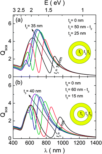 | ||
| Fig. 4 Simulated scattering efficiency for two different configurations of a MDM structure (t0 = 0) of 27 nm total size. The spectra were calculated by (a) keeping t3 = 25 nm and t1 + t2 = 50 nm fixed while varying t2 in-between 10 and 35 nm and (b) keeping t2 = 15 nm and t1 + t3 = 60 nm fixed while varying t3 in-between 15 and 40 nm. | ||
For the MDM structure we have also tested the influence of the outer metallic shell thickness on its optical response (Fig. 4b). In this case the thickness of the dielectric layer (t2 = 25 nm) and the total size (r3 = 75 nm) were kept constant, while the thicknesses of the two metallic layers were varied inversely (t1 + t3 = 60 nm). The reduction of outer metallic layer thickness produces a red-shift of the |ωo−〉 energy mode,48 which, in principle, displaces both dipolar hybridized modes to lower energies. However, the red-shift of the |ω+−〉(1) energy mode is more pronounced, resulting in an increased overlap between both peaks, consequently generating the more intense FR.
Once we have demonstrated the tunability of the FR in MDM structures, we next investigated if additional benefits can be obtained by using an extra layer. The influence of the geometrical parameters on the optical response is, then, analyzed for the DCNs (Fig. 5). With respect to the MDM, this structure has an extra tunable parameter in the aspect ratio of the inner nanoshell (t1/r1), which mainly controls the bonding energy mode of the multilayered structure. The modification of this parameter is exemplified in Fig. 5a, where the thicknesses of the outer layers were kept constant (t2 = 15 nm and t3 = 25 nm) by varying the thicknesses of the two inner layers inversely (t0 + t1 = 35 nm). As can be seen, the reduction of the aspect ratio causes a considerable red-shift of the bonding mode. On the other hand, the position of the antibonding dipole mode of the DCN structure remains largely unchanged. This effect comes from the interaction between the antibonding mode and the lower energy subradiant quadrupole modes, balancing the shifts produced by the modifications of the inner structure.18 The net effect of these variations is the generation of considerably weaker FRs for the higher red-shifts, reducing the practical utility of this parameter. The effects of the dielectric spacing layer and the outer metallic layer were studied for these structures (Fig. 5b and c, respectively). In both cases, the obtained results of geometrical tunability were very similar to the behaviour observed for the equivalent MDM structures. The only appreciable gain is a slight red-shift with respect to their three-layer counterparts. Our results indicate that an appropriate choice of geometric parameters for MDM structures would, then, yield an equivalent FR response, and therefore MDM provides a simpler technological solution.
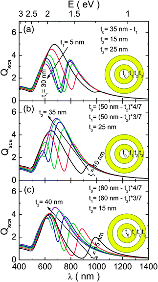 | ||
| Fig. 5 Simulated scattering efficiency for three different configurations of a DCN structure of 75 nm total size. The spectra were calculated by (a) keeping t2 = 15 nm, t3 = 25 nm and t0 + t1 = 35 nm fixed while varying t1 in-between 5 and 30 nm, (b) keeping t3 = 25 nm, t0 + t1 + t2 = 50 nm, and t1/t0 = ¾ fixed while varying t3 in-between 10 and 35 nm and (c) keeping t2 = 15 nm, t0 + t1 + t3 = 60 nm, and t1/t0 = ¾ fixed while varying t3 in-between 15 and 40 nm. | ||
Once we have shown that both the energy and intensity of the FR can be tuned, we setup to quantify these effects in order to provide a useful guidance for the synthesis of structures with the desired response. This quantification can be performed by fitting the calculated spectra of the considered configurations using the expressions developed by Gallinet and Martin,51,52 for Fano resonances on a continuum with the Lorenzian shape:
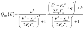 | (1) |
In Gallinet and Martin's approach52 the symmetric resonance given by the first term builds a continuum that is modulated by the asymmetric Fano-like line shape (second term). Finally, in order to properly fit our spectra, it was necessary to add a sigmoidal term [B1 + A1/(1 + exp(−A2 × (E − E0)))] to account for the interband absorption of gold. Here B1, A1, A2 and E0 are the offset, amplitude, slope and position of the sigmoid, respectively. The values for these variables (B1 = −1.66, A1 = 2.21, A2 = 2.84 eV−1 and E0 = 2.5 eV) were determined from a preliminary fit with all the parameters freely adjustable and then all the fits were repeated with the parameters of the sigmoid fixed, since the interband absorption is not expected to change.
Some examples of the fits obtained using eqn (1) are depicted in Fig. 6. As can be seen, the goodness of the fit is very high in the region of the FR. Moreover, the Fano parameter has a negative value when the position of the |ω−−〉(1) mode is lower than the position of the wide |ω+−〉(1) mode (Fig. 6a) and is positive for the inverse case (Fig. 6b).52 The actual shapes of the FRs obtained from the fits are also shown as insets in Fig. 6.
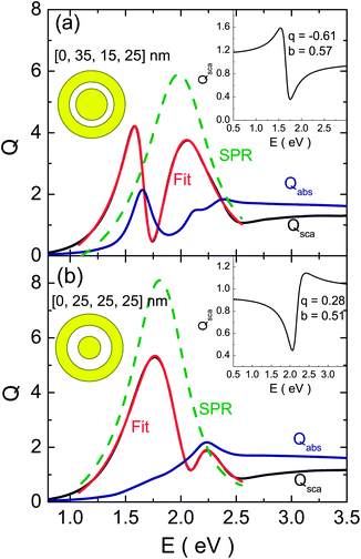 | ||
| Fig. 6 Some typical fits of the scattering spectra using eqn (1); (a) represents a case where the energy position of the dipolar bonding mode is lower than the position of the wide dipolar antibonding mode whereas in (b) the opposite is true. The calculated (using Mie theory) and fitted curves are represented in black and red, respectively and the contribution of the SPR Lorentzian peak was graphed using a green dashed line. The obtained FR shapes are represented in the inset of the figures. | ||
The evolution of the position and line-width of both resonances with the variation of geometrical parameters are also shown, in Fig. 7. The position of both resonances (Fig. 7a) varied on an expected manner,31,49 considering that the Lorentzian SPR and the FR are located at the position of the |ω+−〉(1) and |ω−−〉(1) energy modes, respectively. The FR, in particular, gets blue-shifted almost linearly with the increase of the relevant thickness parameters in all cases,31 deducing energy shifts of nearly 1 eV for a 20 nm change in the relevant thicknesses. The first investigated DCN structure (where the inner shell's parameters are tuned) exhibits, however, a saturation value beyond a given aspect ratio threshold of the inner shell (t1/r1 ∼ 0.6).48 As can be noticed, the shifts of the asymmetric resonance are far more pronounced than those of its symmetric counterpart and, consequently, they intersect at some points, producing some interesting variations of the FR (see below). On the other hand, a rather constant width is observed for both resonances (around 0.1 eV and 0.4 eV for the asymmetric and symmetric peak, respectively), except at the point where they are degenerate in energy, where their widths are almost equal. It should be noted that, however, the spectral overlap of both peaks complicates the analysis and we cannot rule out the fact that this unexpected variation of the peak widths is just an artefact of the fit.
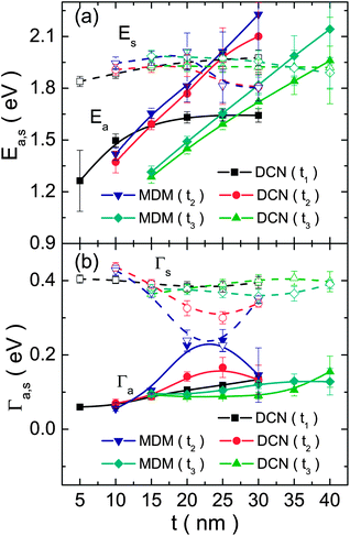 | ||
| Fig. 7 (a) Position and (b) width of the asymmetric (filled symbols, a index) and symmetric (open symbols, s index) resonances, obtained from the fits, as a function of the relevant thickness parameter (specified in the legends) for all the analyzed cases. The lines are just a guide to the eye. | ||
The evolution of the damping (b) and asymmetry (q) parameters can be seen in Fig. 8; it should be recalled that the FR vanishes for b = 1 and q = 0. The modulation damping parameter (and hence the intrinsic losses) exhibits a similar behaviour in all of the analyzed cases. The smaller losses are obtained for the values of t1 and t2 in-between 20 and 25 nm, and t3 ∼ 30 nm. On the other hand, the magnitude of the asymmetry parameter (related to the shape of the FR) decreases monotonically with the increase of t1 for the first case of the DCN (Fig. 8b). An abrupt change in the sign of q is observed when the position of the |ω−−〉(1) energy mode surpasses the value of the |ω+−〉(1) mode, with rather constant values at both sides. Finally, a monotonic increase of the asymmetry parameter value is observed with the increase of t3 (blue-shift of the |ωo−〉 mode). Considering that the intensity of the FR is defined by a combination of b and q (it is more intense for the lower values of b and higher values of |q|); then, adjustment of t2 and t3 values can yield similarly intense FRs for small red-shifts. The latter, however, has the advantage of not affecting considerably the intensity for the largest red-shifts; furthermore, there is not an abrupt variation of the FR shape with the variation of t3 values, as does occur in the case of t2. In all cases, the maximum gains in intensity for the optimal structures are in-between two and four fold, with respect to their non-optimized counterparts.
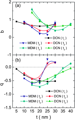 | ||
| Fig. 8 (a) Damping and (b) asymmetry parameters, obtained from the fits, as a function of the relevant thickness parameter (specified in the legends) for all the analyzed cases. The lines are just a guide to the eye. | ||
The quantitative analysis presented in Fig. 7 and 8 can be employed to guide the synthesis of symmetric multilayered nanoshell structures with the desired properties in terms of FR energy, intensity as well as minimizing the losses.
Conclusions
In summary, we have studied the influence of geometrical parameters on the optical responses of symmetric multilayered nanoshells. It has been demonstrated that the dipole–dipole FR arises from the interaction between the wide |ω+−〉(1) energy mode dominated by scattering, and the narrow, mostly absorptive, |ω−−〉(1) energy mode. Although all geometric parameters control to some extent the position and intensity of the Fano resonance, the most important one is the thickness of the outer layer (t3), which allows us to tune the FR position to the infrared region (from 600 nm to 950 nm) with little variations of its intensity. Our results demonstrate that symmetry breaking is not mandatory for controlling the Fano resonance in multilayered plasmonic nanostructures. Generation of all-plasmonic FRs in such symmetric nanostructures presents clear advantages over their asymmetric counterparts (where this effect has been achieved so far) considering their technological advantages and suitability for fabrication.Acknowledgements
OPR thanks the Moncloa Campus of International Excellence (UCM-UPM) for offering a PICATA postdoctoral fellowship. M.C.-Q. thanks the Spanish Ministry of Economy and Competitivity for generous funding through the Ramon y Cajal program, as well as projects MAT2009-10642 and PLE2009-0086.Notes and references
- U. Fano, Phys. Rev., 1961, 124, 1866–1878 CrossRef CAS.
- K.-J. Boller, A. Imamolu and S. E. Harris, Phys. Rev. Lett., 1991, 66, 2593–2596 CrossRef CAS.
- M. Fleischhauer, A. Imamoglu and J. P. Marangos, Rev. Mod. Phys., 2005, 77, 633 CrossRef CAS.
- S. Zhang, D. A. Genov, Y. Wang, M. Liu and X. Zhang, Phys. Rev. Lett., 2008, 101, 047401 CrossRef.
- N. Liu, L. Langguth, T. Weiss, J. Kästel, M. Fleischhauer, T. Pfau and H. Giessen, Nat. Mater., 2009, 8, 758–762 CrossRef CAS.
- N. Liu, T. Weiss, M. Mesch, L. Langguth, U. Eigenthaler, M. Hirscher, C. Sönnichsen and H. Giessen, Nano Lett., 2010, 10, 1103–1107 CrossRef CAS.
- G. Bachelier, I. Russier-Antoine, E. Benichou, C. Jonin, N. Del Fatti, F. Vallée and P.-F. Brevet, Phys. Rev. Lett., 2008, 101, 197401 CrossRef CAS.
- C. Tserkezis, G. Gantzounis and N. Stefanou, J. Phys.: Condens. Matter, 2008, 20, 075232 CrossRef.
- F. Hao, Y. Sonnefraud, P. V. Dorpe, S. A. Maier, N. J. Halas and P. Nordlander, Nano Lett., 2008, 8, 3983–3988 CrossRef CAS.
- M. I. Tribelsky, S. Flach, A. E. Miroshnichenko, A. V. Gorbach and Y. S. Kivshar, Phys. Rev. Lett., 2008, 100, 043903 CrossRef.
- N. Verellen, Y. Sonnefraud, H. Sobhani, F. Hao, V. V. Moshchalkov, P. V. Dorpe, P. Nordlander and S. A. Maier, Nano Lett., 2009, 9, 1663–1667 CrossRef CAS.
- N. A. Mirin, K. Bao and P. Nordlander, J. Phys. Chem. A, 2009, 113, 4028–4034 CrossRef CAS.
- B. Luk'yanchuk, N. I. Zheludev, S. A. Maier, N. J. Halas, P. Nordlander, H. Giessen and C. T. Chong, Nat. Mater., 2010, 9, 707–715 CrossRef CAS.
- S. Mukherjee, H. Sobhani, J. B. Lassiter, R. Bardhan, P. Nordlander and N. J. Halas, Nano Lett., 2010, 10, 2694–2701 CrossRef CAS.
- J. B. Lassiter, H. Sobhani, J. A. Fan, J. Kundu, F. Capasso, P. Nordlander and N. J. Halas, Nano Lett., 2010, 10, 3184–3189 CrossRef CAS.
- J. A. Fan, C. Wu, K. Bao, J. Bao, R. Bardhan, N. J. Halas, V. N. Manoharan, P. Nordlander, G. Shvets and F. Capasso, Science, 2010, 328, 1135–1138 CrossRef CAS.
- P. Nordlander, ACS Nano, 2009, 3, 488–492 CrossRef CAS.
- J. Ho, B. Luk'yanchuk and J. Zhang, Appl. Phys. A: Mater. Sci. Process., 2012, 107, 133–137 CrossRef CAS.
- O. Peña-Rodríguez, U. Pal, M. Campoy-Quiles, L. Rodríguez-Fernández, M. Garriga and M. I. Alonso, J. Phys. Chem. C, 2011, 115, 6410–6414 Search PubMed.
- Z.-J. Yang, Z.-S. Zhang, W. Zhang, Z.-H. Hao and Q.-Q. Wang, Appl. Phys. Lett., 2010, 96, 131113 CrossRef.
- D. Wu, S. Jiang and X. Liu, J. Chem. Phys., 2012, 136, 034502 CrossRef.
- Y. Sonnefraud, N. Verellen, H. Sobhani, G. A. E. Vandenbosch, V. V. Moshchalkov, P. Van Dorpe, P. Nordlander and S. A. Maier, ACS Nano, 2010, 4, 1664–1670 CrossRef CAS.
- Y. H. Fu, J. B. Zhang, Y. F. Yu and B. Luk'yanchuk, ACS Nano, 2012, 6, 5130–5137 CrossRef CAS.
- J. A. Fan, K. Bao, C. Wu, J. Bao, R. Bardhan, N. J. Halas, V. N. Manoharan, G. Shvets, P. Nordlander and F. Capasso, Nano Lett., 2010, 10, 4680–4685 CrossRef CAS.
- S. Zhang, K. Bao, N. J. Halas, H. Xu and P. Nordlander, Nano Lett., 2011, 11, 1657–1663 CrossRef CAS.
- H. Chen, L. Shao, T. Ming, K. C. Woo, Y. C. Man, J. Wang and H.-Q. Lin, ACS Nano, 2011, 5, 6754–6763 CrossRef CAS.
- O. Peña-Rodríguez and U. Pal, Nanoscale, 2011, 3, 3609–3612 RSC.
- D. Wu, S. Jiang and X. Liu, J. Phys. Chem. C, 2011, 115, 23797–23801 CAS.
- H. Chen, L. Shao, Y. C. Man, C. Zhao, J. Wang and B. Yang, Small, 2012, 8, 1503–1509 CrossRef CAS.
- Z. Jian, L. Jian-Jun and Z. Jun-Wu, Plasmonics, 2011, 6, 527–534 CrossRef.
- O. Peña-Rodríguez and U. Pal, J. Phys. Chem. C, 2010, 114, 4414–4417 Search PubMed.
- H. Xu, Phys. Rev. B: Condens. Matter Mater. Phys., 2005, 72, 073405 CrossRef.
- R. Bardhan, S. Mukherjee, N. A. Mirin, S. D. Levit, P. Nordlander and N. J. Halas, J. Phys. Chem. C, 2010, 114, 7378–7383 CAS.
- L. R. Allain and T. Vo-Dinh, Anal. Chim. Acta, 2002, 469, 149–154 CrossRef CAS.
- L. R. Hirsch, J. B. Jackson, A. Lee, N. J. Halas and J. L. West, Anal. Chem., 2003, 75, 2377–2381 CrossRef CAS.
- Y. Cui, B. Ren, J.-L. Yao, R.-A. Gu and Z.-Q. Tian, J. Phys. Chem. B, 2006, 110, 4002–4006 CrossRef CAS.
- W. R. Premasiri, D. T. Moir, M. S. Klempner, N. Krieger, G. Jones and L. D. Ziegler, J. Phys. Chem. B, 2005, 109, 312–320 CrossRef CAS.
- G. Mie, Ann. Phys., 1908, 330, 377–445 CrossRef.
- C. F. Bohren and D. R. Huffman, Absorption and Scattering of Light by Small Particles, Wiley-Interscience, 1998 Search PubMed.
- A. L. Aden and M. Kerker, J. Appl. Phys., 1951, 22, 1242–1246 CrossRef.
- J. Wait, Appl. Sci. Res., Sect. B, 1963, 10, 441–450 Search PubMed.
- R. Bhandari, Appl. Opt., 1985, 24, 1960–1967 CrossRef CAS.
- O. Peña and U. Pal, Comput. Phys. Commun., 2009, 180, 2348–2354 CrossRef.
- W. Yang, Appl. Opt., 2003, 42, 1710–1720 CrossRef.
- E. Prodan, C. Radloff, N. J. Halas and P. Nordlander, Science, 2003, 302, 419–422 CrossRef CAS.
- P. B. Johnson and R. W. Christy, Phys. Rev. B: Solid State, 1972, 6, 4370–4379 CrossRef CAS.
- R. D. Averitt, S. L. Westcott and N. J. Halas, J. Opt. Soc. Am. B, 1999, 16, 1824–1832 CrossRef CAS.
- O. Peña, U. Pal, L. Rodríguez-Fernández and A. Crespo-Sosa, J. Opt. Soc. Am. B, 2008, 25, 1371–1379 CrossRef.
- D. Wu and X. Liu, Appl. Phys. B: Lasers Opt., 2009, 97, 193–197 CrossRef CAS.
- Use of the word ‘intensity’ might not be completely accurate when describing the FR. For the purposes of this work we have considered the intensity of the FR as the difference between the maximum and the minimum of the oscillation.
- B. Gallinet and O. J. F. Martin, Phys. Rev. B: Condens. Matter Mater. Phys., 2011, 83, 235427 CrossRef.
- B. Gallinet and O. J. F. Martin, ACS Nano, 2011, 5, 8999–9008 CrossRef CAS.
| This journal is © The Royal Society of Chemistry 2013 |