Controlling morphology and improving the photovoltaic performances of P3HT/ZnO hybrid solar cells via P3HT-b-PEO as an interfacial compatibilizer
Yueqin
Shi
a,
Fan
Li
*ab and
Yiwang
Chen
*ab
aDepartment of Chemistry/Institute of Polymers, Nanchang University, 999 Xuefu Avenue, Nanchang 330031, China. E-mail: ywchen@ncu.edu.cn; lfan@ncu.edu.cn; Fax: +86 791 83969561; Tel: +86 791 83969562
bJiangxi Provincial Key Laboratory of New Energy Chemistry, Nanchang University, 999 Xuefu Avenue, Nanchang 330031, China
First published on 19th October 2012
Abstract
The well-defined rod–coil diblock copolymer poly(3-hexylthiophene)-b-poly(ethylene oxide) (P3HT-b-PEO) was used as the interfacial compatibilizer for P3HT/ZnO (1![[thin space (1/6-em)]](https://www.rsc.org/images/entities/char_2009.gif) :2 w/w) hybrid heterojunction solar cells. The power conversion efficiency of the device was enhanced from 0.5 to 0.98% in the presence of 0–10 wt% P3HT-b-PEO under illumination of AM 1.5G (100 mW cm−2), resulting from the morphology variation. In the P3HT/ZnO/P3HT-b-PEO ternary blends, the block copolymer does not influence the crystallinity of ZnO NPs, but does influence the crystallinity of P3HT and the dispersion of ZnO NPs. An enhanced crystalline and fiber-like P3HT and more uniform dispersion of ZnO NPs are observed with a small amount of P3HT-b-PEO (10 wt%) loading, leading to a smaller domain size, enhanced interfacial area for charge separation and a favored active layer morphology for improving the device performance. On the other hand, the incorporated P3HT-b-PEO could also suppress macrophase separation during long time thermal annealing and improve the device thermal stability. These results demonstrated that the promising effect of the rod–coil diblock copolymers interfacial compatibilizer for controlling the morphology and improving the performance of hybrid bulk heterojunction solar cells.
:2 w/w) hybrid heterojunction solar cells. The power conversion efficiency of the device was enhanced from 0.5 to 0.98% in the presence of 0–10 wt% P3HT-b-PEO under illumination of AM 1.5G (100 mW cm−2), resulting from the morphology variation. In the P3HT/ZnO/P3HT-b-PEO ternary blends, the block copolymer does not influence the crystallinity of ZnO NPs, but does influence the crystallinity of P3HT and the dispersion of ZnO NPs. An enhanced crystalline and fiber-like P3HT and more uniform dispersion of ZnO NPs are observed with a small amount of P3HT-b-PEO (10 wt%) loading, leading to a smaller domain size, enhanced interfacial area for charge separation and a favored active layer morphology for improving the device performance. On the other hand, the incorporated P3HT-b-PEO could also suppress macrophase separation during long time thermal annealing and improve the device thermal stability. These results demonstrated that the promising effect of the rod–coil diblock copolymers interfacial compatibilizer for controlling the morphology and improving the performance of hybrid bulk heterojunction solar cells.
1 Introduction
Organic–inorganic hybrid bulk heterojunction (BHJ) solar cells incorporating conjugated polymers and nanocrystals as active layers offer the potential to deliver efficient energy conversion with low-cost fabrication. They possess many advantages attributed to conjugated polymers, such as flexibility, light weight, roll-to-roll production, low cost and large area, in conjunction with the tunable optical properties, and physical and chemical stability of inorganic nanocrystals.1–4 However, originating from incompatible interfaces between conjugated polymers and inorganic nanocrystals, hybrid BHJ solar cells based on the blends of conjugated polymers and inorganic nanocrystals suffer from two drawbacks: a poorly controlled electron donor (conjugated polymers)/acceptor (inorganic nanocrystals) phase-separated domain size and inherent thermal instability of morphology. Therefore, the resulting domain size will eventually become larger than the exciton diffusion length and even the device performance will inevitably degrade.5To achieve high charge separation yields, efficient charge transfer and transport in the hybrid BHJ solar cells, the donor and acceptor should self-assemble into domains with dimensions of the order of the exciton diffusion length (10 nm). Thus, the active layer morphology, with appropriate interfaces between conjugated polymers and inorganic nanocrystals in hybrid BHJ solar cells, plays a key role in the power conversion efficiency (PCE). To obtain an optimized nanostructured active layer, thermal annealing,1–3 different solvents (or mixed solvents),6,7 solvent annealing,1–3 processing additives,8 biological synthons, such as DNA and proteins or peptides,9–12 immiscible liquid–liquid interfaces13 and ligands14–18 were commonly utilized, leading to an increase in photovoltaic performance. Thermal annealing was employed in P3HT/PCBM blend systems to optimize the morphology and achieve high efficiency,19 but also led to a dramatic failure of the hybrid solar cell architecture due to poor thermal and dimensional stabilities. Solvent annealing was not suitable for roll-to-roll processes as it required a long exposure time to solvent vapor, which did not fit the requirements of industrial mass production. In addition, via oxidative mechanisms or thermal decomposition, these processes could destroy other parts of the devices such as the electrodes.20 DNA and proteins or peptides were found to be effective in obtaining nanoparticle arrays with tunable symmetry and dimensionality, but large-scale fabrication posed a significant hurdle for practical applications.8 The conventional method for preparing a conjugated polymer/inorganic nanocrystals blend was by mixing a conjugated polymer with inorganic nanocrystals through the use of ligands. However, the ligands would form an insulating interface, even in a nanometric length between the polymer matrix and the nanocrystals, which would further reduce charge transfer ability and might decrease the PCE of the hybrid BHJ solar cells.
In order to overcome the limitations inherent in the above methods, chemical processing additives could be used, including small molecule processing aids and a block copolymer compatibilizer.8,21–25 It is well known that a proper additive could reduce interfacial tension and suppress coalescence,26–28 thereby limiting donor/acceptor domain sizes and improving morphological stability. For photovoltaic applications, the self-assembly of block copolymers was particularly attractive because it was an inexpensive and scalable process that could be designed to produce a stable solid-state composite. On the other hand, when combined with nanocrystals, the self-assembly of block copolymers offered a way to control the organization of inorganic nanocrystals and reduce nanocrystal aggregation.29 Thus, the block copolymer was envisioned to act as a proper polymer compatibilizer for optimizing the active layer morphology in conjugated polymer/inorganic nanocrystal hybrid BHJ solar cells. Recently, some efforts to control the nanoscale film morphology of the BHJ solar cells based on a P3HT/PCBM system by the use of a block copolymer compatibilizer have been reported.21–25 All results showed that a proper block copolymer compatibilizer can reduce the domain size of the blend, retard the rate of phase separation in the blend systems and promote the morphological stability.
Herein, inspired by the above virtues of block copolymers, we use a well-defined block copolymer, poly(3-hexylthiophene)-b-poly(ethylene oxide) (P3HT-b-PEO), as an interfacial compatibilizer for the poly(3-hexylthiophene) (P3HT) and ZnO nanoparticle (NP) hybrid system (P3HT:ZnO 1:2 w/w) to fabricate hybrid BHJ solar cells. The combination of a semiconducting regioregular P3HT block and a non-conjugated flexible PEO block has been shown to generate various highly organized structures. In particular, the well-defined P3HT-b-PEO diblock copolymer has demonstrated increased crystallinity of P3HT chains compared to pristine P3HT.30 Moreover, significant interactions between the two blocks of P3HT-b-PEO diblock copolymer and the P3HT/ZnO blend are expected because of the strong interaction between the oxygen atoms of the PEO chains and the ZnO nanoparticle polar surface,31 in addition to the similarities in the chemical structure of P3HT-b-PEO to the P3HT/ZnO hybrid system. It is expected to acquire an improved P3HT/ZnO blend morphology, enhanced crystallinity of P3HT, a significant enhancement of the solar cell efficiency and improved morphological and device thermal stability compared with hybrid BHJ solar cells based on the pristine blends of P3HT and ZnO nanoparticles.
2 Experimental
Synthesis of P3HT and P3HT-b-PEO
The P3HT (Mn = 10000, PDI < 1.2) was synthesized by Grignard metathesis polymerization. The block copolymer compatibilizer P3HT-b-PEO was synthesized by the Suzuki coupling reaction and the PEO block had a Mn of 400 with a narrow molar mass distribution (PDI < 1.1).30
Synthesis of ZnO nanoparticles
The synthesis of ZnO nanoparticles was carried out under a N2 atmosphere. First, 1.23 g of Zn(Ac)2·2H2O was dissolved in 55 mL of methanol at room temperature. Then, 25 mL of a methanol solution containing 0.48 g of KOH was added dropwise over a 20 min time interval at 60 °C with magnetic stirring. After the KOH solution was added, the solution was stirred at 60 °C for 2 h. The product appears as a white precipitate. After collecting by centrifugation, this white precipitate was washed three times with methanol until it transformed to a gel-like precipitate. Each washing process included dispersion into methanol by sonication and subsequent centrifugation. Finally, the gel-like precipitate was redispersed in 1,2-dichlorobenzene. The ZnO concentration was determined from the solid residue after solvent evaporation. The ZnO solution was used within three days after synthesis, because this led to the highest reproducibility. On average, a ZnO concentration of 45 mg mL−1 was obtained.Preparation of P3HT/ZnO or P3HT/ZnO/P3HT-b-PEO blends
Different ratios of interfacial compatibilizer (0–25 wt% with respect to the amount of P3HT), P3HT-b-PEO, were blended into P3HT/ZnO in 1,2-dichlorobenzene to form homogeneous solutions. In a typical procedure, P3HT (10 mg) or the blend of P3HT (10 mg) and a small amount of P3HT-b-PEO were dissolved in 1,2-dichlorobenzene (556 μL), and 444 μL of ZnO solution was added. Finally, 1 mL of 1,2-dichlorobenzene solution of P3HT/ZnO or P3HT/ZnO/P3HT-b-PEO blend was obtained.Characterizations
The nuclear magnetic resonance (NMR) spectra were collected on a Bruker ARX 400 NMR spectrometer with deuterated chloroform as the solvent and with tetramethylsilane (δ = 0) as the internal standard. The UV-vis spectra of the samples were recorded on a Perkin Elmer Lambda 750s spectrophotometer. Fluorescence measurements for the photoluminescence (PL) of all simples were carried out on a Hitachi F-7000 spectrofluorophotometer with a xenon lamp as the light source. Texture observations by polarizing optical microscopy (POM) were made with a Nikon E600POL polarizing optical microscope equipped with an Instec HS 400 heating and cooling stage. The X-ray diffraction (XRD) study of the samples was carried out on a Bruker D 8 Focus X-ray diffractometer operating at 30 kV and 20 mA with a copper target (λ = 1.54 Å) and at a scanning rate of 1° min−1. TEM images were recorded using a JEOL-2100F transmission electron microscope and an internal charge-coupled device (CCD) camera. To investigate the structures of the crystalline and active layers, transmission electron microscopy (TEM; JEOL, JEM-2100F, field emission transmission electron microscope) was employed. Atomic force microscopy (AFM) images were measured on a nanoscope III A (Digital Instruments) scanning probe microscope using the tapping mode. All the films were spin coated at a spin speed of 1000 rpm for 1 min on the quartz glass for AFM and optical micrographs, while the films made for TEM observations were fabricated as if they were made to be active layers in photovoltaic devices.Device fabrication
All the devices were manufactured with a structure of glass/ITO/PEDOT:PSS/active layer/LiF/Al. The conductive ITO substrates were cleaned by ultrasonication in acetone, soap water, deionized water and isopropanol. After drying the ITO substrates and treating the surface with UV ozone for 15–20 min, poly(3,4-ethylenedioxythiophene):polystyrene sulfonate (PEDOT:PSS) was spin coated onto the surface of indium tin oxide (ITO) at a spin speed of 4000 rpm for 1 min and then dried at 150 °C for 20 min. Subsequently, the 1,2-dichlorobenzene solutions of 20 mg mL−1 ternary blends of P3HT, ZnO NPs (P3HT:ZnO 1:2 w/w) and P3HT-b-PEO were spin coated at a spin speed of 1000 rpm for 1 min. The devices were then thermally annealed at 120 °C for 10 min in a glove box filled with argon. Then the lithium fluoride followed by a layer of aluminum was deposited onto the active layer in a vacuum chamber. I–V curves of the devices were measured under 100 mW cm−2 AM1.5 solar irradiation in ambient air.
3 Results and discussion
Numerous experimental and theoretical studies had demonstrated that the addition of a proper block copolymer compatibilizer to the blends could lead to a reduction of interfacial tension and a decrease of phase separation due to the interaction of block copolymer with the blend components at the interfaces. As shown in Scheme 1, owing to the interaction between the oxygen atoms of the PEO chains and the ZnO polar surfaces, diblock copolymer P3HT-b-PEO would preferentially locate at the interfaces between P3HT and ZnO NPs. The addition of diblock copolymer as an interfacial compatibilizer to P3HT/ZnO blends could lead to a better morphology of conjugated polymers/inorganic nanocrystal hybrid films, enhancement of the hybrid solar cell efficiency and improved device thermal stability. | ||
| Scheme 1 Schematic representation of the morphology of the active layer in the hybrid BHJ solar cells with and without P3HT-b-PEO interfacial compatibilizers. | ||
The optical properties of blend films were used to investigate the molecular organization and charge transfer between conjugated polymers and nanocrystals in the P3HT/ZnO/P3HT-b-PEO ternary blend films, including the UV-vis absorption and PL spectra. The UV-vis spectra of P3HT/ZnO/P3HT-b-PEO ternary blend films with various loadings (0, 5, 10, 15, 25 wt%) of P3HT-b-PEO diblock copolymer are shown in Fig. 1. With the addition of the diblock copolymer, the ternary blended films showed similar absorption spectra compared to the pristine P3HT/ZnO film. In general, P3HT exhibited three characteristic vibronic peaks at 521, 560 and 605 nm32,33 and the intensity at 610 nm was derived from a strong intermolecular interaction of π–π stacking and the crystallinity of the P3HT main chains. Comparing absorption intensities of the blend films at 610 nm, we could find that the addition of a small amount of P3HT-b-PEO diblock copolymer (10 wt%) could improve the packing of P3HT chains slightly.
 | ||
| Fig. 1 UV-vis spectra of P3HT/ZnO (1:2 w/w) blended with 0, 5, 10, 15 and 25 wt% P3HT-b-PEO in thin films on quartz plate using 1,2-dichlorobenzene as the processing solvent. | ||
The PL spectra of P3HT/ZnO/P3HT-b-PEO ternary blend films with various loadings (0, 5, 10, 15, 25 wt%) of P3HT-b-PEO diblock copolymer are shown in Fig. 2. The blend films were excited at 460 nm and the emission spectra were recorded in the range 600–800 nm. Compared with the pristine P3HT/ZnO blend film, all ternary blend films exhibited strong fluorescence quenching, especially for 10% loading of P3HT-b-PEO diblock copolymer, mainly due to the formation of a better heterojunction and the faster deactivation of the excited state by the electron transfer reaction between the polymer donor and the ZnO NP acceptor upon addition of P3HT-b-PEO. The result showed that the addition of a small amount of P3HT-b-PEO diblock copolymer resulted in higher charge separation yields and more efficient charge transfer. Moreover, the fluorescence could be used as a measure of the physical contact between the donor and acceptor in the hybrid BHJ solar cells.34 The strong fluorescence quenching efficiency after the addition of P3HT-b-PEO block copolymer showed the stronger affinity between P3HT and ZnO NPs with the addition of P3HT-b-PEO compatibilizer.
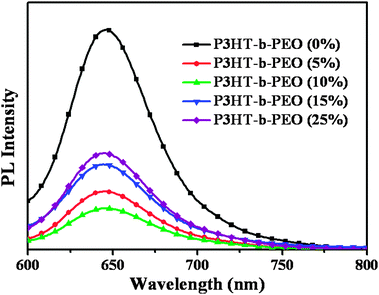 | ||
| Fig. 2 PL spectra of P3HT/ZnO (1:2 w/w) blended with 0, 5, 10, 15 and 25 wt% P3HT-b-PEO in thin films on quartz plates using 1,2-dichlorobenzene as the processing solvent. (λex = 460 nm). | ||
Because polymer chain packing would affect exciton dissociation, recombination and charge transport,35 the crystalline structures of P3HT/ZnO films blended with different amounts of diblock copolymers were observed by XRD measurement as shown in Fig. 3. The diffraction peaks in the range of 30–60° all arose from crystal structures of ZnO. It could be observed that the ZnO crystal structures in the ternary blends were almost unchanged compared with the as-prepared P3HT/ZnO, implying that the addition of compatibilizer P3HT-b-PEO diblock copolymer did not influence the ZnO crystal structures. The diffraction peaks at 2θ ⋍ 6.3° arose from crystallized P3HT chains. It was interesting to note that the obvious increase of diffraction peak intensity was observed after the addition of P3HT-b-PEO diblock copolymer, especially for 10% loading of P3HT-b-PEO diblock copolymer, which reflected the increased crystallization of the P3HT domains. Moreover, the diffraction peak of crystallized P3HT chains in P3HT/ZnO hybrid systems blended with P3HT-b-PEO displayed a shift to a larger d-spacing from 1.46 to 1.66 nm, indicating that the block copolymer P3HT-b-PEO could intercalate between the side chains of P3HT with larger space. The alkyl side chains of the P3HT were expected to vertically align with respect to the substrate surface to form an edge-on orientation and the intermolecular π–π stacking interactions among the thiophene rings were expected to be parallel to the substrate as shown in Fig. 3c,36,37 which might lead to improved exciton dissociation, charge transport and increased photovoltaic performance.
 | ||
| Fig. 3 XRD patterns (a and b) of the P3HT/ZnO (1:2 w/w) blended with 0, 5, 10, 15 and 25 wt% P3HT-b-PEO block copolymer in thin films on quartz plates using 1,2-dichlorobenzene as the processing solvent; (c) schematic model showing the organization of π–π stacking between polythiophene backbones. | ||
AFM analysis was used to further investigate the molecular organization and surface morphology of the ternary blended films. Fig. 4 showed the AFM images of the P3HT/ZnO (1:2 w/w) system with different ratios of rod-coil block copolymer P3HT-b-PEO. The pristine P3HT/ZnO blends showed a rough topography with a root mean square (RMS) surface roughness of 40.862 nm, which indicated a coarse phase separation (Fig. 4a). Using P3HT-b-PEO as the compatibilizer in the P3HT/ZnO blends, the ternary blend films showed much smoother surfaces, especially when 5 and 10 wt% P3HT-b-PEO block copolymers were added. Adding 5 or 10 wt% P3HT-b-PEO block copolymer in the P3HT/ZnO blends showed a smooth surface with a RMS surface roughness of only 7.623 and 8.641 nm, respectively, which implied a better miscibility of P3HT and ZnO NPs when P3HT-b-PEO diblock copolymer was added. However, further increasing the concentration of P3HT-b-PEO diblock copolymer resulted in a rough topography with higher surface roughness, which might be the strong interaction between the oxygen atoms of the PEO chains and ZnO polar surface. Additionally, too much P3HT-b-PEO could make ZnO NPs accumulate within the PEO block, causing a large aggregation of ZnO NPs. Moreover, the samples with 5 or 10 wt% of diblock copolymer P3HT-b-PEO showed phase segregation was minimized and the donor-acceptor interface was maximized compared with the pristine P3HT/ZnO, which might be in favor of the charge generation, transfer and transport, resulting in an increase of Jsc and FF.38
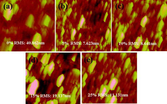 | ||
| Fig. 4 AFM of the P3HT/ZnO (1:2 w/w) blended with (a) 0, (b) 5, (c) 10, (d) 15 and (e) 25 wt% P3HT-b-PEO block copolymer in thin films on quartz plates using 1,2-dichlorobenzene as the processing solvent. The image sizes are all 3 × 3 μm. | ||
Because of the high electron density in ZnO NPs, there was a large contrast between polymer and ZnO NPs, which made TEM an excellent imaging technique to investigate the polymer chain packing and film morphology, as shown in Fig. 5. Compared with the pristine P3HT/ZnO films, ZnO NPs dispersed more uniformly in the blend films with addition of P3HT-b-PEO diblock copolymers. Moreover, the P3HT/ZnO/P3HT-b-PEO ternary blend films all exhibited gray fibril-like structures, mainly due to the crystallization of P3HT. When a small amount of P3HT-b-PEO was added to the hybrid systems, the nanofibril structures were produced and the quantity of fibril-like structures increased compared with the pristine P3HT/ZnO film, especially when 5 and 10 wt% P3HT-b-PEO diblock copolymers were added (Fig. 5b and c), which resulted from the intermolecular interaction of block copolymers, homopolymers and ZnO NPs, leading to the increase of the compatibility between components to induce the orientation change and enhance the ordered stacking of P3HT chains.39 The fibril-like structures were expected to facilitate hole transport within the active layer. In our research, a small amount of P3HT-b-PEO block copolymers was expected to play an important role in controlling the morphology of P3HT/ZnO hybrid systems.
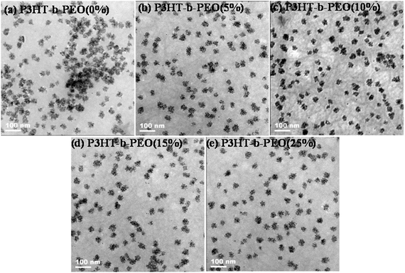 | ||
| Fig. 5 TEM images of P3HT/ZnO NPs blend films with (a) 0, (b) 5, (c) 10, (d) 15 and (e) 25 wt% P3HT-b-PEO block copolymer cast from 1,2-dichlorobenzene. | ||
In order to gain further insight into fibril-like structures, selected area electron diffraction (SAED) patterns of P3HT, P3HT/ZnO and P3HT/ZnO/P3HT-b-PEO ternary films were obtained and are shown in Fig. 6. The outer rings in the electron diffraction patterns were from P3HT and the bright spot rings were from ZnO NPs.28 When ZnO NPs were added, the rings of P3HT became weaker in the pristine P3HT/ZnO blend film, implying that the addition of ZnO NPs could hamper the ordering of P3HT chains. However, upon incorporation of the P3HT-b-PEO diblock copolymer compatibilizer into the P3HT/ZnO blends, the rings of P3HT became obvious again, implying that P3HT-b-PEO diblock copolymer compatibilizer could be attributed to the ordering of P3HT chains and increase the crystallinity of P3HT. The results were consistent with the observations of XRD.
 | ||
| Fig. 6 Selected area electron diffraction patterns of (a) P3HT, (b) P3HT/ZnO nanoparticles and (c) P3HT/ZnO nanoparticles with 10% P3HT-b-PEO. The outer rings in the electron diffraction patterns are from P3HT. | ||
The photovoltaic characteristics of the incorporation of various loading of P3HT-b-PEO diblock copolymer as interfacial compatibilizer in P3HT:ZnO (1:2 w/w) hybrid BHJ solar cells are shown in Fig. 7 and are summarized in Table 1. The power conversion efficiency (PCE) of the corresponding polymer with various loadings of P3HT-b-PEO in the P3HT/ZnO (1:2) system were 0.5 (0 wt%), 0.93 (5 wt%), 0.98 (10 wt%), 0.71 (15 wt%) and 0.56 (25 wt%), respectively, as depicted in Table 1. Compared with the pristine P3HT/ZnO device, the addition of P3HT-b-PEO led to an increase in PCE. Owing to the interaction between the oxygen atoms of the PEO chains and ZnO polar surface and the preferential location of the diblock copolymers at the interface between P3HT and ZnO NPs phases, there existed ordered microphase-separated domains, enhanced crystallinity of P3HT and large interfacial area in the P3HT/ZnO/P3HT-b-PEO ternary blends, resulting in enhanced charge generation, transfer and transport, and thereby, improved device performance.
 | ||
| Fig. 7 Current–voltage characteristics of photovoltaic cells based on P3HT/ZnO with different P3HT-b-PEO block copolymer hybrid films under AM 1.5G illumination from a calibrated solar simulator with an intensity of 100 mW cm−2. | ||
| Devices | J sc (mA cm−2) | V oc (V) | FF | PCE (%) |
|---|---|---|---|---|
| 0% P3HT-b-PEO/ZnO | 2.00 | 0.57 | 0.44 | 0.5 |
| 5% P3HT-b-PEO/ZnO | 3.88 | 0.51 | 0.47 | 0.93 |
| 10% P3HT-b-PEO/ZnO | 3.88 | 0.46 | 0.55 | 0.98 |
| 15% P3HT-b-PEO/ZnO | 2.90 | 0.50 | 0.49 | 0.71 |
| 25% P3HT-b-PEO/ZnO | 2.40 | 0.48 | 0.48 | 0.56 |
The variations in open circuit voltage (Voc), short circuit current density (Jsc), fill factor (FF) and PCE are shown in Fig. 8. As listed in Fig. 8a, the photovoltaic devices showed the various Voc values with different loads of P3HT-b-PEO. It is well-known that the Voc value is strongly affected by not only the energy difference between the HOMO level of the donor and the LUMO level of the acceptor materials, but also by electrode work functions. In our case, the donor and acceptor materials were the same, therefore, the possible reason for various Voc might be the possible interaction between P3HT-b-PEO and the electrode. The dramatic increase of Jsc, especially at 5 and 10 wt% P3HT-b-PEO in these hybrid systems, could be attributed to the increase of the enhanced P3HT crystallinity and the interfacial area between donor and acceptor in the ternary blend active layer, which induced a better phase separation and charge generation, transfer and transport.21–25 As shown in Fig. 8d, the P3HT-b-PEO block copolymer was an effective compatibilizer to enhance the PCE of hybrid BHJ solar cells, especially when 10 wt% block copolymer was added to the P3HT/ZnO hybrid systems. However, PCE decreased as the amount of P3HT-b-PEO diblock copolymer increased from 10 to 25 wt%, because any further addition of P3HT-b-PEO diblock copolymer likely introduced too much insulating PEO components at the P3HT-ZnO interface in the blend, which would hinder the charge transfer at the interface.
 | ||
| Fig. 8 (a) Voc, (b) Jsc, (c) FF and (d) PCE obtained for as cast solar cell at different P3HT-b-PEO block copolymer weight ratios. | ||
To research the effect of P3HT-b-PEO diblock copolymer on the thermal stability of device performance, the PCEs of P3HT/ZnO hybrid BHJ devices with different amounts of P3HT-b-PEO were measured at 120 °C as a function of annealing time, as shown in Fig. 9. As the annealing time increased, the PCE of the pristine P3HT/ZnO was largely reduced from 0.5 to 0.05, however, the devices with addition of P3HT-b-PEO interfacial compatibilizer demonstrated a much smaller decrease in PCE as compared with the standard P3HT/ZnO device, which clearly illustrated that the addition of P3HT-b-PEO diblock copolymer significantly enhanced the thermal stability of device performance in the P3HT/ZnO hybrid BHJ solar cells.
 | ||
| Fig. 9 PCE of P3HT/ZnO NPs/P3HT-b-PEO BHJ hybrid solar cell devices with 0, 5, 10, 15 and 25 wt% addition of P3HT-b-PEO diblock copolymer as a function of annealing time at 120 °C. | ||
In order to research the origin of the thermal stability of P3HT/ZnO/P3HT-b-PEO hybrid BHJ solar cells, the morphology change was monitored as a function of annealing time by using optical microscopy.40 All the films were spin coated at a spin speed of 1000 rpm for 1 min on the quartz glass. As shown in Fig. 10, compared with the pristine P3HT/ZnO, it was observed that the P3HT/ZnO films blended with 10 wt% P3HT-b-PEO block copolymer exhibited few ZnO NPs aggregates even after 6 h annealing at 120 °C. However, the pristine P3HT/ZnO blend film showed many large aggregations of ZnO NPs after 6 h annealing, which might deteriorate the device performance. The results indicated that the P3HT-b-PEO interfacial compatibilizer could suppress the macrophase separation of P3HT/ZnO hybrid system during long-time thermal annealing, leading to improved device thermal stability.
 | ||
| Fig. 10 Optical microscopy images of P3HT/ZnO nanoparticles (1:2 w/w) blended with 0, 5, 10, 15 and 25 wt% of block copolymer P3HT-b-PEO under 120 °C for 10 min and 6 h. (scale bar: 50 μm). | ||
4 Conclusions
In summary, we have utilized a well-defined P3HT-b-PEO diblock copolymer as an interfacial compatibilizer to control P3HT/ZnO hybrid system morphology and thereby improve the power-conversion efficiency. The results demonstrated that a small amount of P3HT-b-PEO diblock copolymer could minimize phase segregation, enhance the crystallinity of P3HT, and improve device thermal stability, mainly thanks to the improved miscibility between P3HT and ZnO NPs due to the interaction between the oxygen atoms of the PEO chains and the ZnO polar surface, and the preferential location of the diblock copolymers at the interface between the P3HT and ZnO NP phases. Overall, the addition of diblock copolymers to control the phase separation and crystallinity of hybrid systems represents a promising way to enhance the photovoltaic properties of hybrid bulk heterojunction solar cells. However, the PCE of the P3HT/ZnO BHJ device in our experiment is low even after being improved by utilizing the compatibilizer. The main reason is that the polymer and ZnO materials employed here have relatively large band gaps and as a consequence, they can not efficiently harvest the available sunlight in the solar spectrum. An improvement of the power conversion efficiency could possibly be improved by designing polymer and inorganic nanocrystal materials with lower band gaps or by changing the device structure.Acknowledgements
Financial support for this work was provided by the National Natural Science Foundation of China (51073076, 51273088, 51172103 and 50902067).References
- A. J. Moulé, L. Chang, C. Thambidurai, R. Vidu and P. Stroeve, J. Mater. Chem., 2012, 22, 2351 RSC.
- P. Reiss, E. Couderc, J. D. Girolamo and A. Pron, Nanoscale, 2011, 3, 466 RSC.
- H. Borchert, Energy Environ. Sci., 2010, 3, 1682 CAS.
- L. Zhao and Z. Lin, Adv. Mater., 2012, 24, 4353 CrossRef CAS.
- S. D. Oosterhout, L. J. A. Koster, S. S. van Bavel, J. Loos, O. Stenzel, R. Thiedmann, V. Schmidt, B. Campo, T. J. Cleij, L. Lutzen, D. Vanderzande, M. M. Wienk and R. A. J. Janssen, Adv. Energy Mater., 2011, 1, 90 CrossRef CAS.
- W. U. Huynh, J. J. Dittmer and A. P. Alivisatos, Science, 2002, 295, 2425 CrossRef CAS.
- S. Ren, L.-Y. Chang, S.-K. Lim, J. Zhao, M. Smith, N. Zhao, V. Bulović, M. Bawendi and S. Gradečak, Nano Lett., 2011, 11, 3998 CrossRef CAS.
- Y. Zhao, K. Thorkelsson, A. J. Mastroianni, T. Schilling, J. M. Luther, B. J. Rancatore, K. Matsunaga, H. Jinnai, Y. Wu, D. Poulsen, J. M. J. Fréchet, A. P. Alivisatos and T. Xu, Nat. Mater., 2009, 8, 979 CrossRef CAS.
- F. Li, D. Gao, X. Zhai, Y. Chen, T. Fu, D. Wu, Z.-P. Zhang, X.-E. Zhang and Q. Wang, Angew. Chem., 2011, 123, 4288 CrossRef.
- S. Pal, Z. Deng, B. Ding, H. Yan and Y. Liu, Angew. Chem., 2010, 122, 2760 CrossRef.
- C.-L. Chen and N. L. Rosi, J. Am. Chem. Soc., 2010, 132, 6902 CrossRef CAS.
- N. Sharma, A. Top, K. L. Kiick and D. J. Pochan, Angew. Chem., 2009, 121, 7212 CrossRef.
- Y. Lin, H. Skaff, T. Emrick, A. D. Dinsmore and T. P. Russell, Science, 2003, 299, 226 CrossRef CAS.
- S. Dowland, T. Lutz, A. Ward, S. P. King, A. Sudlow, M. S. Hill, K. C. Molloy and S. A. Haque, Adv. Mater., 2011, 23, 2739 CrossRef CAS.
- Y. Lin, V. K. Daga, E. R. Anderson, S. P. Gido and J. J. Watkins, J. Am. Chem. Soc., 2011, 133, 6513 CrossRef CAS.
- M. S. Nikolic, C. Olsson, A. Salcher, A. Kornowski, A. Rank, R. Schubert, A. Frömsdorf, H. Weller and S. Förster, Angew. Chem., 2009, 121, 2790 CrossRef.
- Y. Zhou, M. Kogiso and T. Shimizu, J. Am. Chem. Soc., 2009, 131, 2456 CrossRef CAS.
- E. V. Shevchenko, D. V. Talapin, N. A. Kotov, S. O’Brien and C. B. Murray, Nature, 2006, 439, 55 CrossRef CAS.
- G. Li, V. Shrotriya, J. Huang, Y. Yao, T. Moriarty, K. Emery and Y. Yang, Nat. Mater., 2005, 4, 864 CrossRef CAS.
- C. Renaud, S.-J. Mougnier, E. Pavlopoulou, C. Brochon, G. Fleury, D. Deribew, G. Portale, E. Cloutet, S. Chambon, L. Vignau and G. Hadziioannou, Adv. Mater., 2012, 24, 2196 CrossRef CAS.
- C. Renaud, S.-J. Mougnier, E. Pavlopoulou, C. Brochon, G. Fleury, D. Deribew, G. Portale, E. Cloutet, S. Chambon, L. Vignau and G. Hadziioannou, Adv. Mater., 2012, 24, 2196 CrossRef CAS.
- Z. Sun, K. Xiao, J. K. Keum, X. Yu, K. Hong, J. Browning, I. N. Ivanov, J. Chen, J. Alonzo, D. Li, B. G. Sumpter, E. A. Payzant, C. M. Rouleau and D. B. Geohegan, Adv. Mater., 2011, 23, 5529 CrossRef CAS.
- J. Peet, J. Y. Kim, N. E. Coates, W. L. Ma, D. Moses, A. J. Heeger and G. C. Bazan, Nat. Mater., 2007, 6, 497 CrossRef CAS.
- C. Yang, J. K. Lee, A. J. Heeger and F. Wudl, J. Mater. Chem., 2009, 19, 5416 RSC.
- B. K. Sivula, Z. T. Ball, N. Watanabe and J. M. J. Fréchet, Adv. Mater., 2006, 18, 206 CrossRef.
- H.-W. Liu, D.-Y. Chang, W.-Y. Chiu, S.-P. Rwei and L. Wang, J. Mater. Chem., 2012, 22, 15586 RSC.
- F. Machui, S. Rathgeber, N. Li, T. Ameri and C. J. Brabec, J. Mater. Chem., 2012, 22, 15570 RSC.
- J. Chen, X. Yu, K. Hong, J. M. Messman, D. L. Pickel, K. Xiao, M. D. Dadmun, J. W. Mays, A. J. Rondinone, B. G. Sumpter and S. M. Kilbey, J. Mater. Chem., 2012, 22, 13013 RSC.
- L. Li, J. Hollinger, N. Coombs, S. Petrov and D. S. Seferos, Angew. Chem., Int. Ed., 2011, 50, 8148 CrossRef CAS.
- Z. Gu, T. Kanto, K. Tsuchiya, T. Shimomura and K. Ogino, J. Polym. Sci., Part A: Polym. Chem., 2011, 49, 2645 CrossRef CAS.
- S. B. Jo, J. H. Lee, M. Sim, M. Kim, J. H. Park, Y. S. Choi, Y. Kim, S.-G. Ihn and K. Cho, Adv. Energy Mater., 2011, 1, 690 CrossRef CAS.
- X. Yu, K. Xiao, J. Chen, N. V. Lavrik, K. Hong, B. G. Sumpter and D. B. Geohegan, ACS Nano, 2011, 5, 3559 CrossRef CAS.
- Z. Gu, Y. Tan, K. Tsuchiya, T. Shimomura and K. Ogino, Polymers, 2011, 3, 558 CrossRef CAS.
- W.-C. Yen, Y.-H. Lee, J.-F. Lin, C.-A. Dai, U.-S. Jeng and W.-F. Su, Langmuir, 2011, 27, 109 CrossRef CAS.
- D. Han, X. Tong, Y. Zhao and Y. Zhao, Angew. Chem., Int. Ed., 2010, 49, 1 CrossRef.
- A. T. Yiu, P. M. Beaujuge, O. P. Lee, C. H. Woo, M. F. Toney and J. M. J. Fréchet, J. Am. Chem. Soc., 2012, 134, 2180 CrossRef CAS.
- I. Y. Song, J. Kim, M. J. Im, B. J. Moon and T. Park, Macromolecules, 2012, 45, 5058 CrossRef CAS.
- J. Zhang, W. Cai, F. Huang, E. Wang, C. Zhong, S. Liu, M. Wang, C. Duan, T. Yang and Y. Cao, Macromolecules, 2011, 44, 894 CrossRef CAS.
- S. Y. Choi, J. U. Lee, J. W. Lee, S. Lee, Y. J. Song, W. H. Jo and S. H. Kim, Macromolecules, 2011, 44, 1771 CrossRef CAS.
- Y. Zhang, H.-L. Yip, O. Acton, S. K. Hau, F. Huang and A. K.-Y. Jen, Chem. Mater., 2009, 21, 2598 CrossRef CAS.
| This journal is © The Royal Society of Chemistry and the Centre National de la Recherche Scientifique 2013 |