Fine dispersion and self-assembly of ZnO nanoparticles driven by P3HT-b-PEO diblocks for improvement of hybrid solar cells performance
Fan
Li
ab,
Yueqin
Shi
a,
Kai
Yuan
a and
Yiwang
Chen
*ab
aDepartment of Chemistry/Institute of Polymers, Nanchang University, 999 Xuefu Avenue, Nanchang 330031, China. E-mail: ywchen@ncu.edu.cn; Fax: +86 791 83969561; Tel: +86 791 83969562
bJiangxi Provincial Key Laboratory of New Energy Chemistry, Nanchang University, 999 Xuefu Avenue, Nanchang 330031, China
First published on 2nd October 2012
Abstract
The rod-coil conjugated diblock copolymers of poly(3-hexylthiophene)-b-poly(ethylene oxide) (P3HT-b-PEO), acting as an electron donor, were blended with ZnO nanoparticles to fabricate the hybrid bulk-heterojunction (BHJ) solar cells. According to the ultraviolet-visible (UV-vis) absorption spectroscopy, the intensity at 610 nm, derived from a strong inter-molecular interaction of π–π stacking and the high crystallizability of the P3HT main chains, was higher in P3HT-b-PEO/ZnO blend films than that in P3HT/ZnO blend films especially after thermal treatment, revealing that PEO segments could make P3HT form more densely stacked and orderly structured. Due to the nature of block copolymers and the interaction between the oxygen atoms of the PEO chains and the ZnO polar surface, the surface defects of ZnO were passivated and the fine dispersion and self-assembly of ZnO in the polymer matrix driven by the P3HT-b-PEO diblock copolymer was obtained, leading to the improvement of device power conversion efficiency and thermal stability. Overall, this work demonstrated that the application of conjugated block copolymers in hybrid BHJ solar cells was a promising approach to improve the device performance and thermal stability.
1. Introduction
The hybrid bulk heterojunction (BHJ) solar cell of conjugated polymers and inorganic nanocrystals has attracted considerable attention because it offers the potential of combining the best parts of the characteristic properties of the two parts (e.g. assembly, high electron mobility, excellent processability and perfect physical and chemical stability of the inorganic semiconductor)1–4 and it is widely recognized as one of the most promising approaches for producing lightweight and flexible devices to harvest solar energy.5,6 The hybrid BHJ solar cells are fabricated from a blend of conjugated polymers as the electron donor and inorganic semiconducting nanoparticles as the electron acceptor, which are capable of forming the interpenetrating networks and offer larger surface areas for the dissociation of excitons when compared to conventional bilayer heterojunctions. To achieve high power conversion efficiency (PCE), the scale of the hybrid BHJ microstructure should lie in the order of tens of nanometers, which allows photo-generated excitons to reach the interface between p- and n-type semiconductors effectively. Therefore precise control of the active layer morphology is one of the critical issues to obtain high-performance hybrid BHJ solar cells.7–10However, the conjugated polymers and inorganic nanocrystals are chemically incompatible and tend to form uncontrolled macrophase separation, which impedes the photo-induced electron transfer and charge transport and thus reduces the efficiency of the devices. Extensive efforts have been devoted to optimizing the morphology of the hybrid BHJ materials, including the surface modification of inorganic nanocrystals,1–3,6,11–13in situ growth of inorganic nanocrystals in conjugated polymer matrices14–17 and functionalization of conjugated polymers.5 Meanwhile, the phase-separated structure observed in such blend films is assumed to be thermodynamically unstable due to the nature of polymer/inorganic nanoparticles blend, and it is difficult to control the size and orientation of each domain.1–3 Excitingly, the stabilization of polythiophene–ZnO mixtures has been reported for a material wherein the sidechains can be removed recently and this has actually been used in real manufacture of solar cell modules. And their performance is slightly better even if the performance is somewhat below the current state of the art for BHJ type OPV based on fullerene acceptors.18–20
Recently, utilization of conjugated block copolymers (BCPs) as photoactive materials in hybrid bulk heterojunction devices has attracted increasing interest because it is a possible way to overcome these drawbacks. Compared to conjugated homopolymer and polymer blends, due to different thermodynamic properties of the two blocks, block copolymers can self-assemble into ordered, thermodynamically stable and controllable structures on the nanoscale, which could provide optimized morphologies for charge transport.21–32 It offers the opportunity to tailor and optimize the optoelectronic properties for use in photovoltaic cells. The application of conjugated block copolymers in polymer/PCBM solar cells has been widely studied.33–41 However, there are a few reports on the hybrid BHJs made from the blend of conjugated block copolymers and inorganic nanocrystals for solar cell applications. Stefan et al. synthesized poly(3-hexylthiophene)-b-poly(4-vinylpyridine) (P3HT-b-P4VP) and blended it with CdSe quantum dots and they found that incorporation of a poly(4-vinylpyridine) block with P3HT provided a better dispersion of CdSe within the diblock copolymer matrix.42 Su et al. used the blends of poly(3-hexyl thiophene-b-2-vinyl pyridine) (P3HT-b-P2VP) and nicotinic acid-modified titanium dioxide nanoparticles (TiO2) as the active layer to fabricate the P3HT-b-P2VP/TiO2 hybrid solar cells and the results demonstrated that TiO2 NPs were preferentially confined in the P2VP domain of P3HT-b-P2VP at high order and the hybrid device exhibited a >30 fold improvement in PCE as compared to the corresponding 0.3P3HT–0.7P2VP/TiO2 polymer blend hybrid.11 Moreover, we had prepared the diblock copolymer as a molecular template directed in situ synthesised one-dimensional rodlike ZnO nanocrystals assembly43 and mesogen induced self-assembly based on a liquid crystal D–A copolymer and ZnO nanocrystals.44 These studies provide a way to control the morphology of the hybrid active layer and pave the way for the further development of high-efficiency hybrid BHJ solar cells.
In this report, the rod-coil conjugated diblock copolymers of poly(3-hexylthiophene)-b-poly(ethylene oxide) (P3HT-b-PEO) are applied as an electron donor and blended with ZnO nanoparticles to fabricate the P3HT-b-PEO/ZnO hybrid BHJ solar cells. In P3HT-b-PEO, the semicrystalline P3HT is the rod conjugated block and the PEO is the coil segment. The interest for P3HT stems from the combination of high charge carrier mobility, chemically tunable electronic properties, and good solubility. The interest for PEO stems from the better compatibility with ZnO via the interaction between the oxygen atoms of the PEO backbone and the polar surface of ZnO. Moreover, it was reported that the PEO also could fill the surface oxygen vacancies on a ZnO crystal.45,46 It is expected that the more finely dispersed and self-assembled ZnO in the polymer matrix will be obtained driven by the P3HT-b-PEO diblock copolymer, and the charge carrier generation and PCE will be improved. In addition, the thermal stability of the devices prepared using this approach will also be improved in comparison to devices based on P3HT/ZnO blends due to the nature of block copolymers.
2. Experimental
2.1 Materials
All reactions were conducted under prepurified nitrogen, using oven-dried glassware. 2,5-Dibromo-3-hexylthiophene, methylmagnesium bromide in THF (1 M), poly(ethylene oxide) (PEO) monomethyl ether (Mn = 400), 4-(4,4,5,5-tetramethyl-1,3,2-dioxaborolan-2-yl) benzoic acid (BE), N,N-dicyclohexylcarbodiimide (DCC) and N,N-dimethylaminopyridine (DMAP) were purchased from Aldrich and Alfa Aesar and used without any further purification. 1,3-bis(diphenylphosphino)propane nickel(II) chloride and Pd(PPh3)4 were used as received without any further purification. Tetrahydrofuran (THF) and toluene were distilled from sodium. Hexane, methanol, chloroform, chlorobenzene and diethyl ether were obtained from Shanghai Reagent Co. Ltd., and used as received. Indium-tin oxide (ITO) glass was purchased from Delta Technologies Limited while PEDOT:PSS (Baytron PA14083) was obtained from Bayer Inc.2.2 Synthesis of the P3HT–Br
A dry 100 mL two-neck flask was flushed with N2 and charged with 2,5-dibromo-3-hexylthiophene (1.02 g; 3.12 mmol) and dried THF (10 mL). A 1 M solution of methyl magnesium bromide in THF (3.2 mL) was added via a syringe, and refluxed for 2 h under an atmosphere of nitrogen. At this point, the solution changed to yellow. And 1,3-bis(diphenylphosphino) propane nickel(II) chloride (19.6 mg; 0.036 mmol) in 8 mL anhydrous THF was added in one portion by a dry tee, and refluxing was continued for 100 min. Subsequently, the reaction mixture was concentrated to 10 mL and dropped in methanol under vigorous stirring. The precipitate was collected by filtration and washed with methanol. Then, the crude polymer was exhaustively Soxhlet-extracted with methanol and hexanes to remove residual catalysts and short polymer chains. Yield: 0.448 g (80%).2.3 Synthesis of the PEO–BE
To a two-necked flask equipped with a stopcock were added PEO monomethyl ether (Mn = 400, 2.4 g, 4.0 mmol), 4-(4,4,5,5-tetramethyl-1,3,2-dioxaborolan-2-yl) benzoic acid (3.47g, 14.0 mmol), and anhydrous THF (60 mL) under nitrogen. After N,N-dicyclohexylcarbodiimide (DCC) (2.49 g, 12.0 mmol) and N,N-dimethylaminopyridine (DMAP) (1.46 g, 12.0 mmol) were added, the mixture was stirred for 24 h at room temperature. The precipitation was filtered off, and then the mixture was poured into diethyl ether. The precipitation was collected by filtration and washed with diethyl ether. The product was accomplished by column chromatography on silica with dichloromethane![[thin space (1/6-em)]](https://www.rsc.org/images/entities/char_2009.gif) :methanol (10
:methanol (10![[thin space (1/6-em)]](https://www.rsc.org/images/entities/char_2009.gif) :
:![[thin space (1/6-em)]](https://www.rsc.org/images/entities/char_2009.gif) 1) to afford the polymer. Yield: 1.118 g (22.9%).
1) to afford the polymer. Yield: 1.118 g (22.9%).
2.4 Synthesis of P3HT-b-PEO
To a two-necked flask equipped with a stopcock were added P3HT–Br (Mn = 8000, 0.0913 g), PEO–BE (0.024 g, 0.04 mmol), Pd(PPh3)4 (4.34 mg, 0.0043 mmol), and dried toluene (13 mL) under nitrogen. After that 3 M K2CO3 aq. (3 mL) was added, the mixture was stirred at 100 °C for 24 h. The mixture was extracted by chloroform, and the organic layer was dried by MgSO4. The solution was concentrated and poured into methanol to give the polymer. The polymer was exhaustively Soxhlet-extracted with methanol and acetone. Yield was 0.1077 g (85%).2.5 Synthesis of ZnO nanoparticles
The synthesis of ZnO nanoparticles was accomplished using minor modification of the procedure previously described in the literature. The synthesis was carried out under a N2 atmosphere. At first, 1.23 g of Zn(Ac)2·2H2O was dissolved in 55 mL of methanol at room temperature. Then, 25 mL of a methanol solution containing 0.48 g KOH was added dropwise over a 20 min time interval at 60 °C with magnetic stirring. After the KOH solution was added, the solution was stirred at 60 °C for 2 h. The product appeared as a white precipitate. After collecting by centrifugation, this white precipitate was washed three times with methanol until it transformed to a gel-like precipitate. Each washing process included dispersion into methanol by sonication and subsequent centrifugation. Finally, the gel-like precipitate was redispersed in chlorobenzene.2.6 P3HT-b-PEO/ZnO or P3HT/ZnO blend (1![[thin space (1/6-em)]](https://www.rsc.org/images/entities/h3_char_2009.gif) :
:![[thin space (1/6-em)]](https://www.rsc.org/images/entities/h3_char_2009.gif) 2 wt%)
2 wt%)
Blends of P3HT-b-PEO/ZnO or P3HT/ZnO were prepared starting by dissolving P3HT-b-PEO or P3HT in chlorobenzene. The exact amount of the ZnO nanoparticle stock solution needed to reach the desired amounts of ZnO in the blends was determined from the ZnO concentration in the sol. This ZnO concentration was determined from the solid residue after solvent evaporation. The ZnO solution was used within three days after synthesis, because this led to the best cells with the highest reproducibility. On average a ZnO concentration of 45 mg mL−1 had been obtained. In a typical procedure, P3HT-b-PEO or P3HT (20 mg) was dissolved in chlorobenzene (0.655 mL), 690 μL of the ZnO solution was added. Finally, 1 mL chlorobenzene solution of P3HT-b-PEO/ZnO or P3HT/ZnO (1![[thin space (1/6-em)]](https://www.rsc.org/images/entities/char_2009.gif) :
:![[thin space (1/6-em)]](https://www.rsc.org/images/entities/char_2009.gif) 2 wt%) blend was obtained.
2 wt%) blend was obtained.
2.7 Device fabrication
All the devices were manufactured with a structure of Glass/ITO/PEDOT:PSS/active layer/LiF/Al. Poly(3,4-ethylenedioxythiophene):polystyrene sulfonate (PEDOT:PSS) was spin coated onto a glass slide coated by patterned indium tin oxide (ITO). Subsequently, the chlorobenzene solution of 20 mg mL−1 P3HT/ZnO or P3HT-b-PEO/ZnO (1![[thin space (1/6-em)]](https://www.rsc.org/images/entities/char_2009.gif) :
:![[thin space (1/6-em)]](https://www.rsc.org/images/entities/char_2009.gif) 2 wt%) was spin coated. The devices were then thermal annealed at 120 °C for 10 min at a glove box filled with argon. Then the lithium fluoride followed by a layer of aluminum was deposited onto the active layer in a vacuum chamber. The J–V curves of the devices were measured under 100 mW cm−2 AM 1.5 solar irradiation in ambient air.
2 wt%) was spin coated. The devices were then thermal annealed at 120 °C for 10 min at a glove box filled with argon. Then the lithium fluoride followed by a layer of aluminum was deposited onto the active layer in a vacuum chamber. The J–V curves of the devices were measured under 100 mW cm−2 AM 1.5 solar irradiation in ambient air.
3. Characterizations
The nuclear magnetic resonance (NMR) spectra were collected on a Bruker ARX 600 NMR spectrometer with deuterated chloroform as the solvent and with tetramethylsilane (δ = 0) as the internal standard. The ultraviolet-visible (UV) spectra of the samples were recorded on a Perkin-Elmer Lambda 750 spectrophotometer. Fluorescence measurement for photoluminescence (PL) of the polymers was carried out on a Hitachi F-7000 spectrofluorophotometer with a xenon lamp as the light source. Thermogravimetric analysis (TGA) was performed on a Perkin-Elmer TGA 7 for thermogravimetry at a heating rate of 20 °C min−1 under nitrogen with a sample size of 8–10 mg. The X-ray diffraction (XRD) study of the samples was carried out on a Bruker D8 Focus X-ray diffractometer operating at 30 kV and 20 mA with a copper target (λ = 1.54 Å) and at a scanning rate of 1 °C min−1. TEM images were recorded using a JEOL-2100F transmission electron microscope and an internal charge-coupled device (CCD) camera. Atomic force microscopic (AFM) images were measured on a nanoscope III A (Digital Instruments) scanning probe microscope using the tapping mode. For comparison, the optical and photoluminescence properties of the polymers were investigated in thin solid films. Annealing of some films was conducted by heating in the corresponding temperature for 10 min, followed by cooling to room temperature.4. Results and discussion
The blend of poly(3-hexylthiophene)-b-poly(ethylene oxide) (P3HT-b-PEO) rod-coil diblock copolymers and ZnO nanoparticles is applied as the active layer in hybrid heterojunction solar cells. Through the interaction of the ZnO nanoparticles and the oxygen atom of PEO segments, the ZnO nanoparticles are preferentially located in the PEO domain (Scheme 1). The conjugated block copolymer comprising P3HT and PEO segments was prepared by coupling between each homopolymers. P3HT–Br was synthesized by Grignard metathesis polymerization according to ref. 47 A hydroxyl-terminal of PEO was changed to boronic ester (PEO–BE). Finally, the P3HT–Br was coupled with large excess of PEO–BE via the Suzuki coupling reaction to obtain P3HT-b-PEO without PEO–BE which could be removed by Soxhlet-extracted with methanol.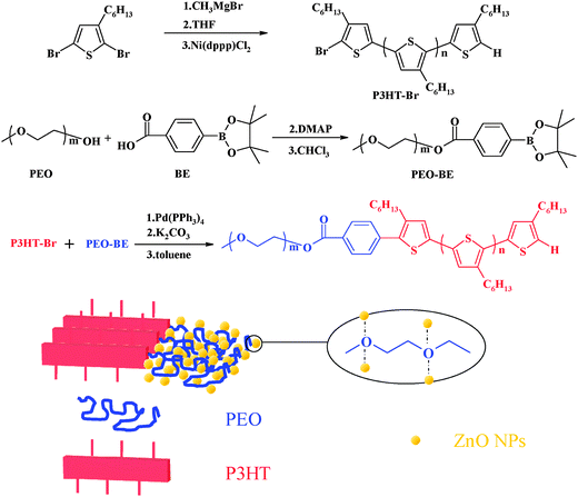 | ||
| Scheme 1 Synthesis of the P3HT-b-PEO block copolymer. | ||
Fig. 1 shows the FT-IR absorption spectra of the PEO, BE and PEO–BE, respectively. The broad absorption peak at 3500 cm−1 can be attributed to the characteristic absorption of hydroxyl groups of PEO. The absorption band at 1690 cm−1 is ascribed to the C![[double bond, length as m-dash]](https://www.rsc.org/images/entities/char_e001.gif) O stretch of the –COOH group of BE, while the absorption band at 1721 cm−1 is attributed to the C
O stretch of the –COOH group of BE, while the absorption band at 1721 cm−1 is attributed to the C![[double bond, length as m-dash]](https://www.rsc.org/images/entities/char_e001.gif) O stretch of the –COO– group of PEO–BE, indicating that the boric acid ester had been successfully linked to the PEO. The absorption band at 2100 cm−1 appearing in the case of PEO–BE was derived from the 1,3-dicyclohexylurea (product of DCC), which could not be completely removed in our experiment.
O stretch of the –COO– group of PEO–BE, indicating that the boric acid ester had been successfully linked to the PEO. The absorption band at 2100 cm−1 appearing in the case of PEO–BE was derived from the 1,3-dicyclohexylurea (product of DCC), which could not be completely removed in our experiment.
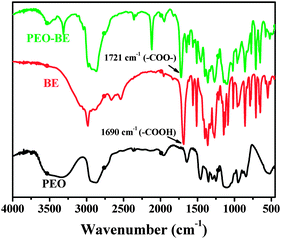 | ||
| Fig. 1 FT-IR spectra of PEO, BE and PEO–BE. | ||
The P3HT-b-PEO block copolymer structure was also confirmed by the 1HNMR spectrum in Fig. 2. In the 1HNMR spectrum of P3HT-b-PEO, the signal assignable to PEO was observed at 3.7 ppm. The protons of the phenyl at 8.1 ppm and 7.5 ppm indicated that the terminal thiophene unit was successfully substituted by PEO segment in Suzuki coupling.
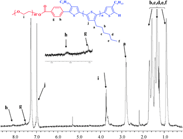 | ||
| Fig. 2 1H NMR spectrum of P3HT-b-PEO in CDCl3. | ||
The thermal properties of P3HT–Br and P3HT-b-PEO were measured by TGA (Fig. 3a). The beginning decomposition temperature of the P3HT-b-PEO block copolymer was higher than the P3HT–Br, indicating the better thermal stability of the P3HT-b-PEO block copolymer. The crystal structures of P3HT–Br and P3HT-b-PEO were also confirmed by XRD (Fig. 3b). The result showed that the crystalline structures of the P3HT-b-PEO diblock copolymer almost had no change compared with the P3HT–Br, implying that the PEO segments did not alter the crystalline structure of the P3HT segments.47
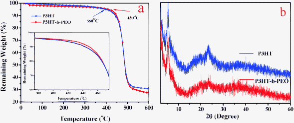 | ||
| Fig. 3 (a) TGA curves and (b) XRD patterns of the P3HT and P3HT-b-PEO. | ||
The optical properties of blend films were useful tools for us to investigate the aggregation state of polymer chains, charge transfer between polymers and nanocrystals and the surface state of nanocrystals. The aggregation state of P3HT chains could be evaluated by UV-vis spectroscopy. Fig. 4 showed the UV-vis absorption spectra for the blend films of the P3HT/ZnO and P3HT-b-PEO/ZnO after the thermal annealing process at various temperatures (100 °C, 120 °C and 150 °C). For all the blend films, an intense absorption characteristic peak was noticed at about 340 nm due to the presence of ZnO nanoparticles. It is well-known that the absorption and emission properties of semiconductor nanoparticles can be tuned over a wide range by controlling the particle size due to the quantum size effect.1 Usually, the absorption edge of ZnO should be expected at slightly higher wavelength of about 370 nm, the intense absorption characteristic peak at about 340 nm in our cases mainly resulted from the decrease in ZnO nanoparticle diameters. Other absorption wavelengths appeared at approximately 520, 560 and 610 nm similar to those of the P3HT film, revealing that the intermolecular π–π stacking of P3HT was not affected by the presence of ZnO and PEO segments. Moreover, a wide absorption band was observed in the P3HT-b-PEO/ZnO nanocomposite films compared to the P3HT/ZnO. And the intensity at 610 nm derived from a strong intermolecular interaction of π–π stacking and the high crystallizability of the P3HT main chains was higher in P3HT-b-PEO/ZnO blend films than that in P3HT/ZnO blend films, indicating that attaching of the PEO chains on the P3HT favored more orderings, and the more orderings led to an increase in effective conjugation and the enhanced hole mobility in the conjugated polymer.47–49 In addition, it could also be observed that the thermal annealing induced a more orderly accumulation of P3HT in P3HT-b-PEO/ZnO blend films, while the aggregation state of P3HT in P3HT/ZnO blend films remained almost unchanged. All results showed that the PEO segments could make P3HT form more densely stacked and more orderly structured, especially after undergoing thermal treatment, even though the ordering of P3HT chains could be hampered by the presence of ZnO nanoparticle aggregates.
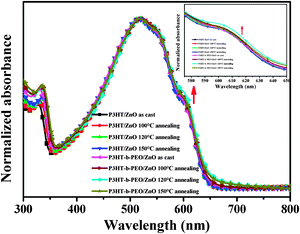 | ||
Fig. 4 UV-vis spectra of P3HT/ZnO and P3HT-b-PEO/ZnO films (1![[thin space (1/6-em)]](https://www.rsc.org/images/entities/char_2009.gif) : :![[thin space (1/6-em)]](https://www.rsc.org/images/entities/char_2009.gif) 2 wt%) under various annealing treatment. 2 wt%) under various annealing treatment. | ||
The pristine P3HT, P3HT-b-PEO, P3HT/ZnO and P3HT-b-PEO/ZnO before and after thermal treatment at 120 °C were excited at 460 nm and the emission spectra were recorded in the range of 500–750 nm, as shown in Fig. 5. Compared to the pristine P3HT and P3HT-b-PEO, PL spectra of P3HT/ZnO and P3HT-b-PEO/ZnO all exhibited strong fluorescence quenching, especially undergoing thermal treatment at 120 °C, mainly due to the formation of heterojunction of P3HT/ZnO and P3HT-b-PEO/ZnO and the fast deactivation of the excited state by the electron-transfer reaction between P3HT, P3HT-b-PEO and ZnO nanoparticles.50
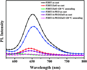 | ||
Fig. 5 PL spectra of P3HT, P3HT-b-PEO, P3HT/ZnO and P3HT-b-PEO/ZnO films (1![[thin space (1/6-em)]](https://www.rsc.org/images/entities/char_2009.gif) : :![[thin space (1/6-em)]](https://www.rsc.org/images/entities/char_2009.gif) 2 wt%) before and after annealing treatment at 120 °C (λEx = 460 nm). 2 wt%) before and after annealing treatment at 120 °C (λEx = 460 nm). | ||
It is well-known that the PL of ZnO is related to the surface defects and crystal quality. To investigate the PL of ZnO nanoparticles in P3HT/ZnO and P3HT-b-PEO/ZnO blend films, we performed another PL measurement using the 325 nm as the excitation wavelength (Fig. 6). As shown in Fig. 6, for the PL spectrum of pristine ZnO nanoparticles, there were a sharp peak at about 360 nm and a broad peak centered at 520 nm. In general, for wurtzite ZnO, there are usually two photoluminescent emission bands. One emission band centered in the UV region is caused by the radiative recombination of electrons from the conduction band with holes from the valence band. And the other broad emission band located in the visible region may be related to some defects induced emission such as oxygen vacancies and zinc interstitials.51,52 After the ZnO nanoparticles were annealed at 120 °C, the intensity of the peak at 360 nm relative to the peak at 520 nm increased, indicating fewer surface defects and better crystal quality. Similar phenomena were observed in the PL spectra of P3HT/ZnO and P3HT-b-PEO/ZnO blend films, revealing that the surface defects of ZnO nanoparticles could be passivated due to the presence of polymer chains and thermal treatment. More interestingly, the ratio of the UV emission intensity to visible emission intensity in the P3HT-b-PEO/ZnO blend film enhanced compared with that in the P3HT/ZnO blend film. The result suggested that the PEO chains effectively wrapped around the ZnO nanoparticles surface and assisted in eliminating surface defects via the interaction between the oxygen atoms of the PEO backbone and ZnO.45,46
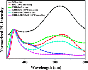 | ||
Fig. 6 Normalized PL spectra of ZnO, P3HT/ZnO and P3HT-b-PEO/ZnO films (1![[thin space (1/6-em)]](https://www.rsc.org/images/entities/char_2009.gif) : :![[thin space (1/6-em)]](https://www.rsc.org/images/entities/char_2009.gif) 2 wt%) under annealing treatment (λEx = 325 nm). 2 wt%) under annealing treatment (λEx = 325 nm). | ||
The active layer morphology is a key factor for the performance of BHJ solar cells. In order to gain insight into the morphology of the blend films, the AFM and TEM were performed. The surface topographies of the P3HT/ZnO and P3HT-b-PEO/ZnO blend films before and after annealing were investigated with tapping mode atomic force microscopy (TM-AFM) (Fig. 7). The as-cast P3HT/ZnO showed rough topographies with a root mean square (RMS) surface roughness of 26.6 nm and the as-cast P3HT-b-PEO/ZnO showed the smoother surface with a RMS surface roughness of 24.3 nm, implying a better miscibility of P3HT-b-PEO and ZnO (Fig. 7a and c). After annealing, the P3HT-b-PEO blend film showed a much smoother surface with a RMS surface roughness of 13.4 nm compared with the annealed P3HT/ZnO blend film, indicating that more fine dispersion of ZnO nanoparticles driven by the P3HT-b-PEO block copolymer (Fig. 7b and d).5 Morever, the most interesting observation in the AFM images was that the structural features (a mixture of spherical features and elongated objects) are visible in the P3HT-b-PEO/ZnO blend annealed at 120 °C. The spherical objects were assigned to the ZnO nanoparticles and the elongated objects were ascribed to the P3HT-b-PEO. In the course of annealing, due to the self-assembly of block copolymers and micro-movement of molecular chains, the accumulation of molecular chains was induced more orderly and the crystallinity of block copolymers also increased, which resulted in elongated objects shown in Fig. 7d.
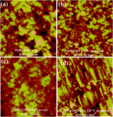 | ||
| Fig. 7 AFM images of P3HT/ZnO blend films (a) as-prepared, (b) annealed at 120 °C for 10 min and P3HT-b-PEO/ZnO blend films (c) as-prepared, (d) annealed at 120 °C for 10 min. The scanning range is 2 μm × 2 μm. | ||
Here, we also used transmission electron microscopy (TEM) to afford information about the morphologies of the active layers between P3HT/ZnO and P3HT-b-PEO/ZnO thin films at the same ZnO concentration (Fig. 8). Both samples were annealed at 120 °C for 10 min. In sharp contrast, the agglomeration of ZnO nanoparticles was reduced in the case of P3HT-b-PEO as compared to P3HT. The TEM image of annealed P3HT/ZnO thin film clearly showed large ZnO clusters and large pure polymer domains in Fig. 8a. As P3HT was the only absorber of visible light in the active layer, these large P3HT domains were unfavorable because the excitons created in such a domain cannot diffuse towards the interface with ZnO during their lifetime and decay before being able to form charges. However, in the annealed P3HT-b-PEO/ZnO thin film, ZnO was much more evenly dispersed inside the polymer matrix in Fig. 8b, which led to more intimate mixing between the rod-coil conjugated block copolymers of P3HT-b-PEO and ZnO nanoparticles and was favorable for charge generation and transport.5 It was interesting that the gray nanofiber-like features were observed in the TEM image of annealed P3HT-b-PEO/ZnO blend film, which was similar to the elongated objects seen in the AFM graph. These gray nanofiber-like areas could be assigned to the rigid P3HT crystalline domains.53 In addition, it should also be noticed that the ZnO nanoparticles were not monodispersed nanoparticles. In contrast, the ZnO nanoparticles self-assembled into the domains on the nanoscale size, which might result from that the ZnO nanoparticles were more selectively associated with the PEO segments. The more detailed mechanism will be investigated in our future research.
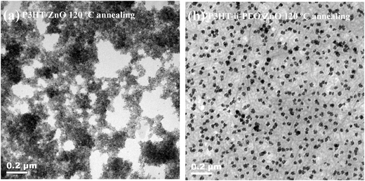 | ||
| Fig. 8 TEM images of (a) P3HT/ZnO nanoparticle blend films annealed at 120 °C and (b) P3HT-b-PEO/ZnO nanoparticles blend films annealed at 120 °C. | ||
The current density–voltage characteristics of these hybrid BHJ devices based on different blend films before and after annealing treatment were shown in Fig. 9. The corresponding photovoltaic parameters, including open circuit voltage (Voc), short-circuit current density (Jsc), fill factor (FF), and power conversion efficiency (PCE) were shown in Table 1. The thermal treatment was carried out under a N2 atmosphere in a glove-box for 10 min. As shown in Table 1, the thermal annealing treatment could lead to a dramatic increase in photovoltaic performance of P3HT/ZnO and P3HT-b-PEO/ZnO blends. The performance improvement was attributed to thermally induced crystallization and nanostructuring of the blend components which resulted in enhanced charge generation and improved charge transport. It should be noticed that the PCE of P3HT-b-PEO/ZnO was higher than that of P3HT/ZnO under the same conditions, mainly resulted from the more fine dispersion and fewer surface defects of ZnO nanoparticles driven by the P3HT-b-PEO diblock copolymer and more densely stacked and orderly structure of P3HT induced by PEO segments.
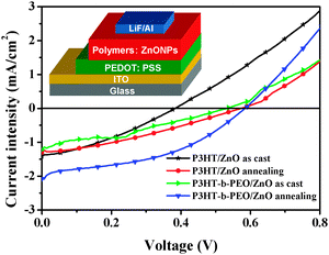 | ||
| Fig. 9 Current–voltage characteristics of photovoltaic cells based on P3HT/ZnO and P3HT-b-PEO/ZnO hybrid films under AM 1.5 G illumination from a calibrated solar simulator with an intensity of 100 mW cm−2. The inset is a schematic of device architecture. | ||
| Devices | J sc (mA cm−2) | V oc (V) | FF | PCE (%) |
|---|---|---|---|---|
| P3HT/ZnO, as cast | 1.42 ± 0.03 | 0.38 ± 0.01 | 0.33 ± 0.01 | 0.18 ± 0.01 |
| P3HT/ZnO, annealing | 1.30 ± 0.04 | 0.57 ± 0.02 | 0.32 ± 0.01 | 0.24 ± 0.02 |
| P3HT-b-PEO/ZnO, as cast | 1.22 ± 0.03 | 0.53 ± 0.01 | 0.32 ± 0.02 | 0.21 ± 0.02 |
| P3HT-b-PEO/ZnO, annealing | 2.08 ± 0.05 | 0.58 ± 0.01 | 0.41 ± 0.01 | 0.49 ± 0.01 |
The intimate compatibility of ZnO nanoparticles towards PEO block of P3HT-b-PEO and the thermodynamical stability of P3HT-b-PEO block copolymers might promote morphological stability under extended annealing and enhance thermal and aging stability of the device. To assess this point, BHJ devices composed of P3HT/ZnO and P3HT-b-PEO/ZnO were fabricated and subsequently annealed at 120 °C for different times in a glove box filled with N2 as an accelerated aging test for device stability. Fig. 10 compared the PCE of these two systems as a function of annealing time. In the course of the thermal annealing, the PCE for P3HT/ZnO increased dramatically for the first 10 min, and then, they gradually decreased to 0.0% after annealing for 3 h. In contrast, the rate of degradation for P3HT-b-PEO/ZnO was much lower, and the PCE remained above 0.2% after annealing for 3 h.
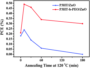 | ||
| Fig. 10 PCE as a function of annealing time for the P3HT/ZnO (blue) and P3HT-b-PEO/ZnO (red) devices. | ||
It had been previously reported that prolonged thermal treatment induced the formation of large aggregates of PCBM in P3HT/PCBM films and degraded device performance.40,54 The optical microscopy images of the active layers were explored to observe the thermal effect on the morphologies of P3HT/ZnO and P3HT-b-PEO/ZnO blend films under harsh annealing conditions at 120 °C as shown in Fig. 11. It was clearly observed that large aggregates of ZnO nanoparticles appeared throughout the P3HT/ZnO films after annealing for 30 min, and after about 120 min of continued annealing, they grew larger in size.40 Conversely, in the case of P3HT-b-PEO/ZnO, only a small number of small ZnO aggregations were observed, even after 120 min of annealing, suggesting that the formation of ZnO aggregations was suppressed by the reduced mobility of the ZnO that was strongly associated with the PEO block.
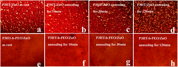 | ||
Fig. 11 Optical microscopy images of P3HT/ZnO NP and P3HT-b-PEO/ZnO NP (1![[thin space (1/6-em)]](https://www.rsc.org/images/entities/char_2009.gif) : :![[thin space (1/6-em)]](https://www.rsc.org/images/entities/char_2009.gif) 2 wt%) blend films under various thermal annealing times at 120 °C. 2 wt%) blend films under various thermal annealing times at 120 °C. | ||
5. Conclusions
In summary, the P3HT-b-PEO diblock copolymers have been successfully applied in hybrid bulk-heterojunction polymer/ZnO solar cells. Compared with the P3HT/ZnO blend system, more fine dispersion and self-assembly of ZnO nanoparticles in the polymer matrix driven by the P3HT-b-PEO block copolymer and reduction of ZnO nanoparticles surface defects will be obtained, stemming from the interaction between the oxygen atoms of the PEO segments and the polar ZnO surface. Therefore, the use of P3HT-b-PEO led to a much finer phase separation when blended with ZnO, and hence, led to the improvement of device performance. In addition, the thermal stability of the devices prepared using this approach will also be enhanced in comparison to devices based on P3HT/ZnO blends due to the nature of block copolymers and the better compatibility.Acknowledgements
This work was supported by the National Natural Science Foundation of China (51073076, 51273088, 51172103 and 50902067).References
- H. Borchert, Energy Environ. Sci., 2010, 3, 1682–1694 RSC.
- P. Reiss, E. Couderc, J. D. Girolamo and A. Pron, Nanoscale, 2011, 3, 466–489 Search PubMed.
- A. J. Moulé, L. L. Chang, C. Thambidurai, R. Vidu and P. Stroeve, J. Mater. Chem., 2012, 22, 2351–2368 RSC.
- C. Burda, X. Chen, R. Narayanan and M. A. El-Sayed, Chem. Rev., 2005, 105, 1025–1102 CrossRef CAS.
- S. D. Oosterhout, L. J. A. Koster, S. S. V. Bavel, J. Loos, O. Stenzel, R. Thiedmann, V. Schmidt, B. Campo, T. J. Cleij, L. Lutzen, D. Vanderzande, M. M. Wienk and R. A. J. Janssen, Adv. Energy Mater., 2011, 1, 90–96 Search PubMed.
- E. Martinez-Ferrero, J. Albero and E. Palomares, J. Phys. Chem. Lett., 2010, 1, 3039–3045 Search PubMed.
- L. Han, D. Qin, X. Jiang, Y. Liu, L. Wang, J. Chen and Y. Cao, Nanotechnology, 2006, 17, 4736–4742 CrossRef CAS.
- Y. Zhou, Y. C. Li, H. Z. Zhong, J. H. Hou, Y. Q. Ding, C. H. Yang and Y. F. Li, Nanotechnology, 2006, 17, 4041–4047 CrossRef CAS.
- W. U. Huynh, J. J. Dittmer, W. C. Libby, G. L. Whiting and A. P. Alivisatos, Adv. Funct. Mater., 2003, 13, 73–79 CrossRef CAS.
- B. Sun and N. C. Greenham, Phys. Chem. Chem. Phys., 2006, 8, 3557–3560 RSC.
- W.-C. Yen, Y.-H. Lee, J.-F. Lin, C.-A. Dai, U.-S. Jeng and W.-F. Su, Langmuir, 2011, 27, 109–115 CrossRef CAS.
- Y. Lin, V. K. Daga, E. R. Anderson, S. P. Gido and J. J. Watkins, J. Am. Chem. Soc., 2011, 133, 6513–6516 CrossRef CAS.
- S. Y. Yang, C.-F. Wang and S. Chen, J. Am. Chem. Soc., 2011, 133, 8412–8415 CrossRef CAS.
- K. Palaniappan, J. W. Murphy, N. Khanam, J. Horvath, H. Alshareef, M. Quevedo-Lopez, M. C. Biewer, S. Y. Park, M. J. Kim, B. E. Gnade and M. C. Stefan, Macromolecules, 2009, 42, 3845–3849 CrossRef CAS.
- X. M. Peng, L. Zhang, Y. W. Chen, F. Li and W. H. Zhou, Appl. Surf. Sci., 2010, 256, 2948–2955 CrossRef CAS.
- A. Stavrinadis, S. Xu, J. H. Warner, J. L. Hutchison, J. M. Smith and A. A. R. Watt, Nanotechnology, 2009, 20, 445608-1–445608-7 Search PubMed.
- H. C. Leventis, S. P. King, A. Sudlow, M. S. Hill, K. C. Molloy and S. A. Haque, Nano Lett., 2010, 10, 1253–1258 CrossRef CAS.
- F. C. Krebs, Sol. Energy Mater. Sol. Cells, 2008, 92, 715–726 CrossRef CAS.
- F. C. Krebs, Y. Thomann, R. Thomann and J. W. Andreasen, Nanotechnology, 2008, 19, 424013–424024 CrossRef.
- F. C. Krebs, M. Jørgensen, K. Norrman, O. Hagemann, J. Alstrup, T. D. Nielsen, J. Fyenbo, K. Larsen and J. Kristensen, Sol. Energy Mater. Sol. Cells, 2009, 93, 422–441 CrossRef CAS.
- N. Sary, F. Richard, C. Brochon, N. Leclerc, P. Lévěque, J.-N. Audinot, S. Berson, T. Heiser, G. Hadziioannou and R. Mezzenga, Adv. Mater., 2010, 22, 763–768 CrossRef CAS.
- M. Sommer, S. M. Lindner and M. Thelakkat, Adv. Funct. Mater., 2007, 17, 1493–1500 CrossRef CAS.
- S. S. Sun, C. Zhang, A. Ledbetter, S. Choi, K. Seo, C. E. Bonner, M. Drees and N. S. Sariciftci, Appl. Phys. Lett., 2007, 90, 043117-1–043117-3 Search PubMed.
- G. Sauve and R. D. McCullough, Adv. Mater., 2007, 19, 1822–1825 CrossRef CAS.
- C. Brochon, N. Sary, R. Mezzenga, C. Ngov, F. Richard, M. May and G. Hadziioannou, J. Appl. Polym. Sci., 2008, 110, 3664–3670 CrossRef CAS.
- B. de Boer, U. Stalmach, P. F. van Hutten, C. Melzer, V. V. Krasnikov and G. Hadziioannou, Polymer, 2001, 42, 9097–9109 CrossRef CAS.
- U. Stalmach, B. de Boer, C. Videlot, P. F. van Hutten and G. Hadziioannou, J. Am. Chem. Soc., 2000, 122, 5464–5472 CrossRef CAS.
- U. Stalmach, B. de Boer, A. D. Post, P. F. van Hutten and G. Hadziioannou, Angew. Chem., Int. Ed., 2001, 40, 428–430 Search PubMed.
- M. H. Van der Veen, B. de Boer, U. Stalmach, K. I. Van de Wetering and G. Hadziioannou, Macromolecules, 2004, 37, 3673–3684 CrossRef CAS.
- K. V. D. Wetering, C. Brochon, C. Ngov and G. Hadziioannou, Macromolecules, 2006, 39, 4289–4297 CrossRef.
- J. S. Liu, E. Sheina, T. Kowalewski and R. D. McCullough, Angew. Chem., Int. Ed., 2002, 41, 329–332 CrossRef CAS.
- C. L. Chochos, J. K. Kallitsis and V. G. Gregoriou, J. Phys. Chem. B, 2005, 109, 8755–8760 CrossRef CAS.
- P. K. Tsolakis, J. K. Kallitsis and A. Godt, Macromolecules, 2002, 35, 5758–5762 Search PubMed.
- S. Kim, Y. Kakuda, A. Yokoyama and T. Yokozawa, J. Polym. Sci., Part A: Polym. Chem., 2007, 45, 3129–3133 Search PubMed.
- F. Richard, C. Brochon, N. Leclerc, D. Eckhardt, T. Heiser and G. Hadziioannou, Macromol. Rapid Commun., 2008, 29, 885–891 CrossRef CAS.
- S. Barrau, T. Heiser, F. Richard, C. Brochon, C. Ngov, K. Van de Wetering, G. Hadziioannou, D. V. Anokhin and D. A. Ivanov, Macromolecules, 2008, 41, 2701–2710 CrossRef CAS.
- M. S. Rahman, S. Samal and J. S. Lee, Macromolecules, 2006, 39, 5009–5014 CrossRef CAS.
- T. Heiser, G. Adamopoulos, M. Brinkmann, U. Giovanella, S. Ould-Saad, C. Brochon, K. Van de Wetering and G. Hadziioannou, Thin Solid Films, 2006, 511, 219–223 CrossRef.
- M. Urien, H. Erothu, E. Cloutet, R. C. Hiorns, L. Vignau and H. Cramail, Macromolecules, 2008, 41, 7033–7040 CrossRef CAS.
- Y. Lin, J. A. Lim, Q. S. Wei, S. C. B. Mannsfeld, A. L. Briseno and J. J. Watkins, Chem. Mater., 2012, 24, 622–632 CrossRef CAS.
- C. Renaud, S.-J. Mougnier, E. Pavlopoulou, C. Brochon, G. Fleury, D. Deribew, G. Portale, E. Cloutet, S. Chambon, L. Vignau and G. Hadziioannou, Adv. Mater., 2012, 24, 2196–2201 Search PubMed.
- K. Palaniappan, N. Hundt, P. Sista, H. Nguyen, J. Hao, M. P. Bhatt, Y.-Y. Han, E. A. Schmiedel, E. E. Sheina, M. C. Biewer and M. C. Stefan, J. Polym. Sci., Part A: Polym. Chem., 2011, 49, 1802–1808 CrossRef CAS.
- K. Yuan, F. Li, Y. Chen, X. Wang and L. Chen, J. Mater. Chem., 2011, 21, 11886–11894 RSC.
- F. Li, W. Chen and Y. Chen, J. Mater. Chem., 2012, 22, 6259–6266 RSC.
- S. B. Jo, J. H. Lee, M. Sim, M. Kim, J. H. Park, Y. S. Choi, Y. Kim, S.-G. Ihn and K. Cho, Adv. Energy Mater., 2011, 1, 690–698 Search PubMed.
- X. M. Sui, C. L. Shao and Y. C. Liu, Polymer, 2007, 48, 1459–1463 Search PubMed.
- Z. J. Gu, T. Kanto, K. Tsuchiya, T. Shimomura and K. Ogino, J. Polym. Sci., Part A: Polym. Chem., 2011, 49, 2645–2652 CrossRef CAS.
- Z. Z. Sun, K. Xiao, J. K. Keum, X. Yu, K. L. Hong and J. Browning, Adv. Mater., 2011, 23, 5529–5535 CrossRef CAS.
- X. Yu, K. Xiao, J. H. Chen, N. V. Lavrik, K. L. Hong, B. G. Sumpter and D. B. Geohegan, ACS Nano, 2011, 5, 3559–3567 CrossRef CAS.
- J. Xu, J. Wang, M. Mitchell, P. Mukherjee, M. Jeffries-EL, J. W. Petrich and Z. Lin, J. Am. Chem. Soc., 2007, 129, 12828–12833 CrossRef CAS.
- L. Y. Zhang, L. W. Yin, C. X. Wang, N. Lun, Y. X. Qi and D. Xiang, J. Phys. Chem. C, 2010, 114, 9651–9658 CrossRef CAS.
- P. Podbršček, G. Dražić, J. A. Paramo, Y. M. Strzhemechny, J. Maček and Z. C. Orel, CrystEngComm, 2010, 12, 3071–3079 RSC.
- G. Grancharov, O. Coulembier, M. Surin, R. Lazzaroni and P. Dubois, Macromolecules, 2010, 43, 8957–8964 CrossRef CAS.
- J.-H. Tsai, Y.-C. Lai, T. Higashihara, C.-J. Lin, M. Ueda and W.-C. Chen, Macromolecules, 2010, 43, 6085–6091 CrossRef CAS.
| This journal is © The Royal Society of Chemistry and the Centre National de la Recherche Scientifique 2013 |
