Research highlights
Mark W. Tibbitta, Ali Fathib, Fariba Dehghanib, Mehmet R. Dokmecicd and Ali Khademhosseini*cdef
aKoch Institute for Integrative Cancer Research, Department of Chemical Engineering, Massachusetts Institute of Technology, Cambridge, Massachusetts 02139, USA
bSchool of Chemical and Biomolecular Engineering, The University of Sydney, Sydney, 2006, Australia
cCenter for Biomedical Engineering, Department of Medicine, Brigham and Women's Hospital, Harvard Medical School, Cambridge, Massachusetts 02139, USA. E-mail: alik@rics.bwh.harvard.edu
dHarvard-MIT Division of Health Sciences and Technology, Massachusetts Institute of Technology, Cambridge, Massachusetts 02139, USA
eWyss Institute for Biologically Inspired Engineering, Harvard University, Boston, Massachusetts 02115, USA
fWorld Premier International – Advanced Institute for Materials Research (WPI-AIMR), Tohoku University, Sendai 980-8577, Japan
First published on 5th July 2013
Low-cost nanoprinting of proteins
High throughput printing of proteins is often needed for the fabrication of biosensors, microarrays and creation of cell alignment in bioanalysis and tissue engineering.1 Current microengineering techniques often involve harsh conditions such as prolonged exposure to light and sudden pH changes that are not favourable for patterning delicate biomolecules such as proteins, as they are susceptible to denaturation. Other alternative approaches such as inkjet printing and parallel dip-pen patterning have been suggested. However, due to their low resolution and lack of control of the size and dimensions of the patterns they have limited applications for protein patterning. More advanced methods such as lift-off printing with silicon (Si) master stamps are technically favourable for the generation of fine patterns with high resolution but the high costs involved in the fabrication of a non-recyclable Si stamp is a burden limiting their widespread use.Ricoult et al. have recently developed a low cost high throughput printing approach to circumvent the issues in patterning proteins.2 Their method involves replication of a Si stamp with low cost poly(dimethylsiloxane) (PDMS) and Norland Optical Adhesive 63 (NOA) polymers. In the approach shown in Fig. 1, after creating the silicon mold with nanopatterns, the authors transfer the features from silicon to a PDMS mold and then to a UV crosslinkable NOA polymer. Then they attach the nanostructured NOA polymer surface to a PDMS substrate coated with proteins. They next separate the two substrates, selectively removing the proteins from the PDMS surface that are in contact with the nanopatterns on the NOA surface. After this step, by pressing the PDMS substrate onto a glass substrate, they transfer the biomolecules from the PDMS onto a glass surface. The researchers have used this approach for precise patterning of biomolecules and created two dimensional digital nanodot gradients (DNGs) of different proteins. The recyclable template is rapidly produced and can be used for high throughput production of biomolecule patterns under moderate conditions. The authors mention that it is possible to fabricate 400 copies of PDMS–NOA templates from a single Si master. This massive replication reduces the cost associated with the lift-off technique that involves the direct use of a Si wafer. Additionally, the processing time for the replication of NOA from PDMS is less than a minute, which allows tens of NOA copies to be rapidly produced.
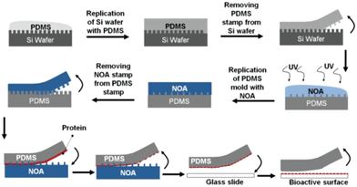 | ||
| Fig. 1 Creation of a bioactive surface using a lift-off approach by PDMS and NOA replicates from a Si wafer. | ||
The authors demonstrated diverse applications for nanodot patterning and created various bioactive surfaces. In one example, they fabricated DNGs of arginine-glycine-aspartic acid (RGD) on the surface of an inert coverslip.2 It has been reported that protein aggregates with dimensions less than 200 nm fail to elicit cell responses.3 Therefore, RGD dots with a diameter of 200 nm were generated. A solution of 75 v% poly-L-lysine grafted with polyethylene glycol and 25 v% poly-D-lysine was added to the coverslip to backfill the surface with an inert background to intensify the response of cells to DNGs. C2C12 myoblast cells were seeded on the surface, adhered, formed filopodia and migrated along the DNGs of RGD peptides. As a negative control for the DNG samples, immunoglobulin G was patterned instead of the RGD peptides. In these samples, cells lost their adhesion and left the surface within 24 h post seeding. This result indicates that cells specifically respond to the peptides and the lift-off printing approach with the replicates is an efficient method for the generation of bioactive surfaces.
In the second experiment, netrin-1 protein, which is a chemoattractant for myoblasts was patterned as the DNG to study the haptotaxis and movement of cells within the bioactive surface. Fluorescence imaging at 18 h post-seeding showed that cells had an affinity to proliferate and collected in the high density netrin-1 regions. Quantitative cell haptotaxis showed that 50% of the cells were located within 30 μm of the highest density regions of netrin-1. The authors observed that the cells in the center regions of the gradient migrated toward the higher density regions whereas cells in the lower end sites migrated in random directions and many left the surface. The results of this experiment demonstrated the viability of controlling the haptotaxis of cells by using DNGs generated with the lift-off technique.
In summary, the method presented is cost effective for the generation of nanoscale patterns with a resolution of about 30 nm. This technique is favourable for the fabrication of bioactive surfaces for a broad range of applications including cell alignment, biological analysis and imaging. One concern in this method is the generation of defects that are mainly attributed to absorbed dust particles on the PDMS stamp during the replication process. Conducting the whole manufacturing process in a clean room can resolve this issue. In addition, the NOA stamp can be used only once for patterning as multiple printing results in the generation of more defects. A thorough cleaning protocol might resolve this problem and enable the use of NOA stamps for multiple printing cycles. Further optimization and improvement of this advanced nanoprinting technique may lead to nanopatterning of biomolecules that can be used in many disparate fields.
Spinning cellular thread
To improve the clinical success of cell-based therapies and organ replacement, a range of materials are being explored as cell delivery vehicles and building blocks for tissue engineering. These cell scaffolds, often formed from natural and/or synthetic polymers, provide a permissive niche for cell viability and can be engineered to promote cell function while minimizing the immune response.4 Further, the materials should enable assembly into complex units that recapitulate organ level structure and function. Three-dimensional hydrogels have emerged as effective materials for cell delivery and organ regeneration; however, clinical success remains limited and opportunities for novel approaches exist.Recently, Onoe et al. presented a strategy to fabricate metre-long microfibres comprised of cells that can be employed to deliver cells to the body or to weave complex structures for tissue engineering.5 This innovative technique relies on a microfluidic device that facilitates the fabrication of coaxial, core–shell microfibres. The inner layer of the microfibres is comprised of cells suspended in a solution of extracellular matrix (ECM) components (e.g., collagen or fibrin). The cell suspension is encased in an alginate based hydrogel providing structural support while the ECM components form a gel. Finally, the alginate sheath is removed selectively once the cells have spontaneously formed tissue-like microfibres. Once the cells have assembled into fibres or tubes, the constructs remain robust and can be manipulated for catheter based injection or woven into multicellular constructs.
Onoe et al. designed the microfluidic device (Fig. 2) such that a solution of cells and ECM components, which takes minutes to hours to gel, could be housed within a stable shell of rapidly gelling alginate. As the CaCl2 solution mixes with the Na-alginate in the outer layer (∼50 μm thick) a robust gel was formed which allowed for rapid production of metre-long fibres (∼200 μm diameter). Since the approach is modular, a range of cell-types were encapsulated within the core (∼100 μm diameter) of the microfibres, including fibroblasts, cardiomyocytes, endothelial cells, cortical cells, neural stem cells, and islet cells. In each case, the cells were allowed to self-assemble within the alginate sheath (1–4 days). Once the cells assembled the sheath was removed by gentle treatment with a solution of alginate lyase (4 mg mL−1) for 15 min.
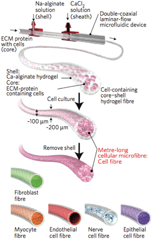 | ||
| Fig. 2 Schematic of the fabrication of core–shell, cell-laden microfibres. A suspension of ECM proteins and cells was gelled within a core of calcium crosslinked alginate. Once the cells assemble into a microtissue structure, the alginate was removed, resulting in long cell-laden microfibres. Reprinted by permission from Macmillan Publishers Ltd: ref. 5, copyright 2013. | ||
Following removal of the alginate sheath, the morphologies and functions of the cellular microfibres were investigated. Cardiomyocytes assembled into actively contractile fibres; human umbilical vein endothelial cells formed tubular structures with an open inner diameter of 23 ± 4 μm; cortical cells aligned their dendrites in the direction of the fiber comprising an aligned neural network with synchronized Ca2+ oscillations; neural stem cells differentiated into neurons and glial cells within the fibre construct. Since the cellular threads remained robust after sheath removal, the authors cleverly manipulated the fibres into complex higher-order assemblies. Individual fibres were handled using capillaries and wrapped around a glass rod to form a large scale tubular structure (∼1 mm diameter and ∼10 mm long) or loaded onto a micro-loom. When fibers were fed into the micro-loom they were woven into fabric-like sheets of multiple cell types, enabling defined cell–cell contacts in large-scale structures. Cells retained function after manipulation and hepatocyte-laden fibres increased albumin production when co-cultured with fibroblast-laden fibres. Finally, islet cells were encapsulated within a microfibre and implanted into the subrenal capsular space of diabetic mice using a microcatheter. The animals that received the cell-based therapy maintained normal glucose levels for up to 13 days.
In all, this unique fabrication of metre-long and cell-laden fibres presents a viable approach for catheter based cell transplantation and another building block for constructing organs outside of the body. One can imagine vascularizing tissue constructs with long, fibre-formed endothelial tubules or weaving a cardiac patch from fibres of cardiomyocytes. While the potential applications seem boundless, it is important to consider the long-term efficacy of such constructs in the body and the organism's immune response. Yet, the future looks promising and tissue engineers may need to add cellular textiles to their toolbox.
Blood clotting under pressure
The circulatory system cycles blood to all parts of the body through a network of high-pressure veins and arteries. When a region of the vasculature – the system of veins and arteries – is damaged, blood exits the vessel forming a hematoma in the surrounding tissue. To prevent excessive hematoma formation, the body has adapted to quickly patch injuries through thrombus formation.6 A thrombus, or blood clot, forms when the vascular endothelium is disrupted, exposing sub-endothelial collagen and tissue factor. Collagen binds and activates platelets from the blood stream to nucleate the thrombus while tissue factor initiates thrombin production and fibrinogen conversion to fibrin. Rapid thrombus formation patches the damaged vessel and provides time for the wounded endothelium to heal. The general mechanism of thrombus formation is understood; however, few in vitro platforms exist to study thrombus formation in depth and in a hemodynamic setting.Now, Muthard and Diamond have provided a microfluidic platform that facilitates orthogonal control over shear stress and pressure at the site of thrombus formation.7 Shear stress and transthrombus pressure gradients are both thought to influence clot formation in vivo, but until recently it has been difficult to study these effects in vitro and in a controlled fashion. The authors designed a microfluidic device around a thrombus inducing chamber that housed collagen with or without tissue factor, along the side of a channel through which blood can flow with hemodynamic shear stresses (initially, 5.2 dynes cm−2 or 33.9 dynes cm−2). An additional inlet was placed downstream of the thrombus-inducing chamber so that the transthrombus pressure could be controlled in real-time by regulating the downstream resistance to flow in the channel (Fig. 3). A feedback loop received inputs from pressure sensors on both sides of the thrombus and regulated the downstream flow rate to maintain appropriate transthrombus pressures (11.3 to 30 mm Hg) independent of the upstream flow rate. Since the thrombus chamber exposed collagen (with or without tissue factor), platelets from the blood deposited on the collagen and initiated thrombus formation. This enabled the researchers to investigate how thrombus thickness and permeability is influenced by both shear stress and transthrombus pressure.
 | ||
| Fig. 3 Schematic of the thrombus microfluidic device. (A) Blood flows in at Inlet Q1 upstream of the thrombus and at Inlet Q2 to regulate the shear stress and transthrombus pressure. Pressure sensors at P1, P2, and P3 monitored the transthrombus pressure and maintained it by controlling the flow rates at Q1 and Q2. (B) At the junction of Outlet P3 and the main channel, a thrombus-inducing chamber was made containing collagen (with or without tissue factor) around a series of support pillars. Figure reprinted with permission from the Royal Society of Chemistry from Muthard and Diamond.7 | ||
Initial studies with the microfluidic thrombus device confirmed that the authors could deposit collagen with or without tissue factor into the thrombus-inducing chamber and expose it to blood at arterial (33.9 dynes cm−2) or venous (5.2 dynes cm−2) wall shear stresses. Further, in both cases, the transthrombus pressure could be tightly regulated over a range of physiologic pressures (20.6 to 30 mm Hg for arterial shear; 11.3 to 22.5 mm Hg for venous shear). In all cases, platelets deposited on the collagen and initiated thrombus formation. Interestingly, it was observed that increased transthrombus pressure (23.4 mm Hg compared to 20.8 or 0 mm Hg) resulted in decreased thrombus thickness. Furthermore, the increased transthrombus pressure decreased the distance that thrombin was able to diffuse from the collagen chamber into the forming clot, as the pressure provided convective resistance to the thrombin diffusion.
In all, the device presented by Muthard and Diamond significantly expands the range of physiologic conditions in which thrombus formation can be studied. This has implications in pathological thrombus formation, such as thrombosis, as well as understanding the basic function of wound healing in the vasculature. In the future, similar devices that enable orthogonal control over shear stress and pressure may be adapted to angiogenesis and, more broadly, branching morphogenesis.
References
- A. Sassolas, B. D. Leca-Bouvier and L. J. Blum, Chem. Rev., 2008, 108, 109–139 CrossRef CAS.
- S. G. Ricoult, M. Pla-Roca, R. Safavieh, G. M. Lopez-Ayon, P. Gruetter, T. E. Kennedy and D. Juncker, Small, 2013 DOI:10.1002/smll.201202915.
- B. Geiger, J. P. Spatz and A. D. Bershadsky, Nat. Rev. Mol. Cell Biol., 2009, 10, 21–33 CrossRef CAS.
- M. W. Tibbitt and K. S. Anseth, Biotechnol. Bioeng., 2009, 103, 655–663 CrossRef CAS.
- H. Onoe, T. Okitsu, A. Itou, M. Kato-Negishi, R. Gojo, D. Kiriya, K. Sato, S. Miura, S. Iwanaga, K. Kuribayashi-Shigetomi, Y. T. Matsunaga, Y. Shimoyama and S. Takeuchi, Nat. Mater., 2013, 12, 584–590 CrossRef CAS.
- B. Furie and B. C. Furie, N. Engl. J. Med., 2008, 359, 938–949 CrossRef CAS.
- R. W. Muthard and S. L. Diamond, Lab Chip, 2013, 13, 1883–1891 RSC.
| This journal is © The Royal Society of Chemistry 2013 |