Research highlights
Nasim
Annabi
abc,
Hojae
Bae
d,
Mehmet R.
Dokmeci
ab and
Ali
Khademhosseini
*abce
aCenter for Biomedical Engineering, Department of Medicine, Brigham and Women's Hospital, Harvard Medical School, Cambridge, Massachusetts 02139, USA. E-mail: alik@rics.bwh.harvard.edu
bHarvard-MIT Division of Health Sciences and Technology, Massachusetts Institute of Technology, Cambridge, Massachusetts 02139, USA
cWyss Institute for Biologically Inspired Engineering, Harvard University, Boston, Massachusetts 02115, USA
dCollege of Animal Bioscience and Technology, Department of Bioindustrial Technologies, Konkuk University, Hwayang-dong, Kwangjin-gu, Seoul 143-701, Republic of Korea
eWorld Premier International–Advanced Institute for Materials Research (WPI-AIMR), Tohoku University, Sendai 980-8577, Japan
First published on 23rd May 2013
A perfusable vascular network
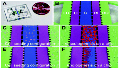
Engineering functional blood vessels in vitro can be used to investigate the dynamics and functions of native vessels. It can be also utilized to create and study disease dynamics on-chip, as well as to discover drugs and therapeutics for different vascular diseases. However, successful development of these functional vasculatures remains a significant challenge. For example, 2D systems have been developed by seeding endothelial cells (ECs), the main cell type for blood vessel formation, on a substrate, but these systems do not replicate the biological complexities of the native 3D blood vessels. To address this limitation, microfluidic channels have been successfully utilized to generate perfusable 3D vasculature systems by seeding ECs inside the channels to form hollow structures. Despite the significant progress in making 3D vascularized networks, these systems could not mimic complex endothelial dynamics in actual vasculogenesis (formation of new blood vessels when there are no pre-existing ones) and angiogenesis (formation of new blood vessels through sprouting from pre-existing vessels), thus exhibiting artifacts in the structural and functional aspects of the resulting vasculature.An ideal engineered blood vessel should be perfusable, have barrier function, and produce nitric oxide (NO) under certain stimuli. Jeon et al. engineered a novel microfluidic platform to create 3D perfusable and functional vasculatures in a gel matrix.1 The polydimethylsiloxane (PDMS)-based device consisted of five parallel channels, a central channel (C) flanked by two microfluidic channels (LI, RI) and two stromal cell culture channels (LO, RO) (Fig. 1A, B). A spatially patterned co-culture of ECs (in the central channel) and perivascular cells (in LO or RO) in this single platform was used to induce two distinct processes of blood vessel formation, vasculogenesis (Fig. 1C, D) and angiogenesis (Fig. 1E, F). In a patterned co-culture system of EC-fibroblasts, fibroblast-secreted growth factors from the stromal channels were shown to promote both vasculogenic and angiogenic processes. In the vasculogenic process, the secreted growth factors from both LO and RO channels supported the ECs, which were encapsulated in the fibrin gel in the central channel, to form a complex interconnected architecture at day 4 (Fig. 1D). In contrast, using a co-culture of ECs and fibroblasts resulted in a well-interconnected, but non-perfusable vascular network. To induce angiogenesis, ECs were seeded on the left side-wall of the central channel filled by the gel. Fibroblasts were also seeded on the opposite side in the RO channel, exposing ECs to a gradient of fibroblast-secreted factors to induce the formation of angiogenic sprouts within the gel, forming mature microvascular networks during 4 days of sprout extension and maturation. (Fig. 1F). It was found that this co-culture system of ECs and fibroblasts induced robust formation of intact and readily perfusable microvascular networks.
 | ||
| Fig. 1 An image of the chip (A) and its structure (B): Central channel C; cell culture medium channels Left Inside, LI; Right Inside, RI; and two outside stromal cell culture channels Left Outside, LO; Right Outside, RO. (C, D) Cell-seeding configuration for the vasculogenesis experiment with ECs embedded in a 3D fibrin matrix inside the central channel, and fibroblasts within fibrin matrices in the LO and RO channels. (E, F) Cell-seeding configuration for the angiogenesis experiment with ECs coated on the side of the central channel filled with fibrin matrix and fibroblasts in a fibrin matrix placed in the RO channel. Figure adapted and reprinted with permission from the Royal Society of Chemistry from Kim et al.1 | ||
After the formation of a stable and perfusable 3D microvasculature, the effect of fluid flow on the cytoskeleton reorganization and activation of NO synthesis, a crucial signaling molecule for vascular physiology, was investigated. The mechanical forces induced by fluid flow enhanced the NO production and facilitated the cell filament reorganization along the longitudinal axis of the tubules as early as 2 h after perfusion.
The platform that was developed in this paper allowed for the integration of critical microenvironmental factors that resemble the in vivo blood vessel environment. The developed device was combined with patterned co-culture systems to study diverse types of cell–cell interactions in a single platform. In contrast to previous studies on vascular formation based on only endothelialization of hydrogel constructs,2 the reported platform facilitated the formation of vasculature with intact barrier function and 3D architecture, resembling the native blood vessel. This versatile platform has the potential to be used as an in vitro model for further investigation of functional and structural variations of blood vessels in response to biochemical and biophysical cues.
A gradient generating microfluidic chip
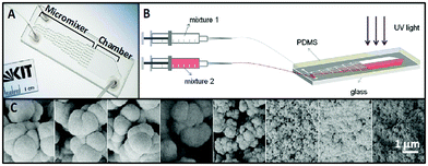
The porosity of tissue engineering scaffolds plays a critical role in tissue formation both in vitro and in vivo.3 For example, the presence of pores on the surface of the scaffolds can promote in vitro cell attachment and growth. To study the effects of scaffold porosity on cellular behavior, gradients of porosity and pore size have been generated in both 2D and 3D constructs.4 These gradients were created using different techniques, such as electrochemical etching,5 3D fiber deposition,6 and centrifugal forces.7 However, these techniques are incompatible with miniaturized platforms for in vitro studies of cellular responses to biomaterial porosity.Kreppenhofer et al.8 developed a PDMS-based microfluidic chip to fabricate thin films of polymers containing gradients of pore sizes in the range of 100 to 500 nm. The microfluidic device consisted of a cascade micromixer to generate a gradient of two polymer solutions, and a reaction chamber for the photo-polymerization and formation of a polymer film having a pore size gradient (Fig. 2A). The chip was fabricated by reversible bonding of a microstructured PDMS layer, formed using a micromilled aluminium master, to a glass slide. To form a polymer gradient film, two polymer mixtures containing different types of porogen were injected into the device using two syringe pumps. Mixture one contained cyclohexanol as the porogen to form a polymer film with a pore size in the range of tens of nanometers, and mixture two had 1-decanol as a porogen to create pore sizes of 1–2 μm in the polymer film. After the formation of a gradient, the microfluidic chip was placed under UV light for 15 min to photo-polymerize the polymer solution inside the chamber (Fig. 2B). The PDMS layer was then removed from the glass slide, leaving the polymer film containing the porogens. The film was kept in methanol overnight to remove the porogens and create a porosity gradient on the polymer film (Fig. 2C).
 | ||
| Fig. 2 (A) A PDMS-based microfluidic device for generating polymer films with pore size gradients. The chip consisted of a network of zigzag mixing channels and a reaction chamber. (B) A polymer gradient film was created by injecting polymer mixtures containing porogen into the device using a syringe pump, and polymerization of polymer gradient was carried out with UV light. (C) The gradient porous film was generated after removing porogens from the polymer film. Figure adapted and reprinted with permission from Langmuir from Kreppenhofer et al.8 | ||
The effects of the injection flow rate and fluid density on gradient formation were investigated using microscopic laser-induced fluorescence to visualize the concentration gradient in the reaction chamber, and electron microscopy analysis to measure the pore sizes in the polymer film. At higher flow rates a sharp step-like pore gradient was formed, however, low flow rates led to the formation of shallower gradients. To visualize the gradient shape, a fluorescence marker was dissolved in one of the two injected fluids and the formation of the gradient was assessed by taking images of the chamber using a fluorescence microscope.9 For fluids with the same density, linear concentration gradients were formed both at a low flow rate (0.001 mL min−1), due to the diffusive mixing, and at a high flow rate (20 mL min−1), due to convection mixing when transversal secondary flows arise as a consequence of the meandering shape of the zigzag channels. In addition, no mixing occurred when using 1 mL min−1, as the flow was too fast for diffusion mixing and too slow for the secondary flows.
Gradient patterns were altered when fluids with different densities were used. For example, a linear concentration gradient was formed at a flow rate of 1 mL min−1 by using fluids with different densities. In this case, the fluid with a lower density tends to slip over the higher density one, which resulted in the formation of an apparent uniform concentration at a low flow rate (0.001 mL min−1). However, a 2D wedge-like arrangement of the two fluids was formed at a higher flow rate (1 mL min−1) when there is less time for the fluid with the lower density to slip over the more dense liquid. The density-driven wedge-like gradient resulted in the formation of a polymer film containing a gradient of pore sizes.
This study demonstrated the formation of polymer surfaces having a gradient of pore sizes by using a microfluidic device. The designed platform can be used as a convenient way to generate porous polymer films with a gradient of porosity to investigate cell-scaffold surface interactions. However, one of the limitations of the chip is the possible absorption of porogens by the PDMS layer, which may limit the control over the pore sizes generated across the polymer film.
Storing data on a microfluidic chip
Since its early days of development, microfluidics technology has been used in the development of various applications, such as DNA analysis and cell/tissue culture. With the advancement of this technology, highly specialized microfluidic devices are being built for numerous applications, such that the functionality and process parameters are different and specific to each device. Henceforth, it would be a tremendous advantage if information, such as the expiration date, process and operation parameters can be stored on a chip and readily retrieved. Despite this clear need, very few approaches exist to store and retrieve data on a chip in a simple, scalable and programmable manner.Gijs and colleagues have previously demonstrated parylene-C as a bonding layer and a structural material to form microfluidic channels.10 In their recent study, Ciftlik et al.11 explored the possibility of storing and rewriting data using this intermediate layer by characterizing the fluorescence behaviour of parylene-C under illumination. They demonstrated that the UV light can be used to enhance the fluorescence of parylene-C, whereas the use of green light decreased its fluorescence. Thus, by patterning a surface in such a manner a bar code can be generated.
To fabricate such device, they first coated a pyrex wafer with a parylene-C film and etched channels inside this film. Next, fluidic inlet holes were opened in a silicon wafer and the two wafers were bonded in vacuum. To pattern the surface, an inverted fluorescent microscope with a CCD camera having a high-pressure mercury lamp was used to provide sufficient UV illumination to a wider area.
First, the intermediate parylene-C bonding layer fluorescence (iPBLF) was evaluated by quantifying the fluorescence of the parylene-C pattern. Short time exposure (<1 s) using 6 different filter sets (excitation/emission) was done to show that patterned parylene-C fluorescence was significant only under UV and green light excitation. Next, the time dependence of iPBLF was performed under long-term illumination using the UV/blue and green/red filter sets where the UV illumination induced fluorescence in both cases. Interesting behavior resulted from the green light illumination, which resulted in the bleaching (decrease) of iPBLF when observed in the green/red filter set. To further establish the technique, long-term stability of a spot formed by UV (induced fluorescence) and green light (bleaching) illumination was studied for over 7 days. The results suggested that the written information on parylene-C substrates remained stable over such a time period.
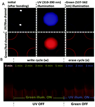
From the above preliminary analysis, induced fluorescence observed in the green/red channel was shown to have an opposite trend depending on the light source (UV or green), while bleaching was not observed in the UV/blue channel (Fig. 3A). Therefore, the induced fluorescence by UV light and bleaching by green light at a single region can be exploited for re-writable data storage on-chip. The green illumination was used to decrease the iPBLF fluorescence intensity to “write”, while subsequent UV illumination at the same spot was used to “erase” by reversing the bleaching effect (Fig. 3B).
 | ||
| Fig. 3 A schematic representation of a ‘write’ and ‘erase’ cycle by illumination and an example of an iPBLF application for automated operation of the microfluidic chip. (A) Fluorescence observation before and after UV and green light illumination. (B) Dynamic programming of iPBLF using green and UV light. The green illumination decreases fluorescence to ‘write’ and the UV illumination is used in the same region to ‘erase’ by reversing the effect. Figure adapted and reprinted with permission from the Royal Society of Chemistry from Ciftlik et al.10 | ||
The applications of iPBLF are diverse for creating data storage on-chip, such as making Quick Response (QR)-codes that can easily be engraved and modified. As a proof of concept, microfluidic devices were exposed to UV using a standard lithography mask to mark each device with a QR-code that could be read by a smart phone. In particular, the irreversible UV/blue channel fluorescence was used for read-only applications and the green/red channel was used for modifiable applications. To test the long-term stability of the code, the chip was stored at room temperature for 2 months and the code could still be recognized by the software.
The proposed method utilized the complementary behaviour of iPBLF fluorescence intensity under UV and green light illumination. The authors verified the possibility to ‘write’ or ‘erase’ the fluorescence for many cycles, which indicated that iPBLF can be used for diverse applications, including measuring device dimensions and data storage. Despite the promising results, more work is needed to explore miniaturization of the codes, and characterization of long term drift and stability of the smaller structures. The iPBLF's versatility as a bonding/structural layer and its ability to store data could directly benefit industrial exploitation of microfluidics in the biomedical field by enabling higher reproducibility and operational control of device parameters.
References
- S. Kim, H. Lee, M. Chung and N. L. Jeon, Lab Chip, 2013, 13, 1489–1500 RSC.
- E. C. Novosel, C. Kleinhans and P. J. Kluger, Adv. Drug Delivery Rev., 2011, 63, 300–311 CrossRef CAS.
- N. Annabi, J. W. Nichol, X. Zhong, C. Ji, S. Koshy, A. Khademhosseini and F. Dehghani, Tissue Eng., Part B: Rev., 2010, 16, 371–380 CrossRef CAS.
- S. Sant, M. J. Hancock, J. P. Donnelly, D. Iyer and A. Khademhosseini, Can. J. Chem. Eng., 2010, 88, 899–911 CrossRef CAS.
- P.-Y. Wang, L. R. Clements, H. Thissen, A. Jane, W.-B. Tsai and N. H. Voelcker, Adv. Funct. Mater., 2012, 22, 3414–3423 CrossRef CAS.
- T. B. Woodfield, C. A. Van Blitterswijk, J. De Wijn, T. J. Sims, A. P. Hollander and J. Riesle, Tissue Eng., 2005, 11, 1297–1311 CrossRef CAS.
- S. H. Oh, I. K. Park, J. M. Kim and J. H. Lee, Biomaterials, 2007, 28, 1664–1671 CrossRef CAS.
- K. Kreppenhofer, J. Li, R. Segura, L. Popp, M. Rossi, P. Tzvetkova, B. Luy, C. J. Kahler, A. E. Guber and P. A. Levkin, Langmuir, 2013, 29, 3797–3804 CrossRef CAS.
- N. Jeon, S. Dertinger, D. Chiu, I. Choi, A. Stroock and G. Whitesides, Langmuir, 2000, 16, 8311–8316 CrossRef CAS.
- A. T. Ciftlik and M. A. M. Gijs, Lab Chip, 2012, 12, 396–400 RSC.
- A. T. Ciftlik, D. G. Dupouy and M. A. M. Gijs, Lab Chip, 2013, 13, 1482–1488 RSC.
| This journal is © The Royal Society of Chemistry 2013 |
