Development of automated paper-based devices for sequential multistep sandwich enzyme-linked immunosorbent assays using inkjet printing†
Amara
Apilux
ab,
Yoshiaki
Ukita
a,
Miyuki
Chikae
a,
Orawon
Chailapakul
*bc and
Yuzuru
Takamura
*a
aSchool of Materials Science, Japan Advanced Institute of Science and Technology, 1-1 Asahidai, Nomi City, Ishikawa 923-1292, Japan. E-mail: yztakamura@jaist.ac.jp; Fax: +81-761-51-1665; Tel: +81-761-51-1661
bDepartment of Chemistry, Faculty of Science, Chulalongkorn University, 254 Phayathai Road, Patumwan, Bangkok 10330, Thailand. E-mail: corawon@chula.ac.th; Fax: +66-2-218-7615; Tel: +66-2-218-7615
cCenter of Excellence for Petroleum, Petrochemicals and Advanced Materials, Chulalongkorn University, 254 Phayathai Road, Patumwan, Bangkok 10330, Thailand
First published on 24th October 2012
Abstract
To the best of our knowledge, this is the first report on paper-based devices for automating the sequential multistep procedures of a sandwich-type enzyme-linked immunosorbent assay (ELISA) that require only a single-step application of the sample solution. The device was based on a piece of nitrocellulose (NC) membrane with specially designed channels, where all the reagents are applied at different locations in order to control the fluid travel to the detection region. The inkjet printing method, a simple and low-cost process, was used to create the flow channel and device barrier patterns. The fabricated barrier was found to be an efficient boundary for the liquid along the printed design in the NC membrane, enabling direct control of the reagent flow time. ELISA results were obtained with a single-step sample application. The developed devices (so-called automated paper-based devices) provided a simple procedure for the sandwich ELISA, while reducing assay time and reagent consumption. Colorimetric results were measured using digital camera imaging with software processing. The capability of the method developed herein was successfully used to determine the levels of human chorionic gonadotropin (hCG) by ELISA.
Introduction
The enzyme-linked immunosorbent assay (ELISA) is a commonly used method for biochemical analysis because it provides high specificity and high sensitivity via signal amplification.1 However, typical sandwich-type ELISAs require a multistep process of mixing, washing, and incubation, the entirety of which is complicated and time consuming. Therefore, there is an increasing need for the development of simpler devices that allow for a one-step assay protocol and are portable for rapid analysis. An enzyme-linked immunostrip biosensor for sandwich ELISAs has been developed.2,3 In this method, the sensor strip is placed into the sample solution to absorb the solution into the strip in the vertical direction. After the immuno-reaction, 2 pads (the substrate application pad and absorption pad) are arranged on each lateral side of the signal generation pad of the sensor strip to absorb substrate flow in the horizontal direction. Although this method has been successful for sandwich ELISAs, it still requires manual input by the user, and the device needs several types of different functional membranes to prepare the immunochromatographic assay sensor strip.Paper-based microfluidic devices, whereby microfluidic platforms are created on paper-based material, have recently received considerable attention for the development of point-of-care diagnostics because they are easy to use, rapid, inexpensive, and portable.4 They require small volumes of the reagent and do not require an external power source. Nitrocellulose (NC) membranes, which are a porous hydrophilic paper-like substrate, have been used as the paper-based material in this approach because they have a uniform pore size, smooth surface, and high protein-binding capability, which makes them suitable for protein immobilization.5,6 Recently, several methods, including photolithography,7 plasma oxidation,8 and plotting,9 have been reported to create a hydrophobic barrier to control the fluid direction or the rate of the fluid absorption on paper. However, each of these methods has some disadvantages. For example, photolithography requires multiple steps to fabricate the device. Additionally, the NC membrane can be damaged in the developing step, plasma oxidation requires a specific mask, and the plotting method provides only a low resolution of the barrier. As an alternative, inkjet printing is very attractive because it enables direct patterning onto the material surface, which saves time, reduces the number of steps without loss of resolution, and can be used for patterning various kinds of materials, including NC membranes. Therefore, we utilized this inkjet printing method in the current study.
Most paper-based devices have been created recently for multi-analysis using a simple colorimetric bioassay.10–13 Prior to use, the reagent(s) for the assay are spotted and dried onto the test zone of the device during fabrication of the paper-based devices. The entrance channel is dipped into the test sample to introduce the sample to the test zone during analysis. These systems are limited to a single-step reaction with one-time sample loading since multistep reactions would require multistep handling. A paper-based device for ELISA has been reported;14,15 the ELISA was performed on paper or an NC membrane. Although this method provided a high level of sensitivity, it required multiple steps, and each step required manual operations, which is somewhat similar to the conventional ELISA format. Therefore, it is not ideally suited for point-of-care diagnostics. Additionally, two-dimensional paper networks that can be used to drive multistep sequences autonomously have been reported.16,17 The timing for the reagent travel can be controlled by changing the path length of each inlet and the volume of fluid applied to each inlet. By this method, all reagents were introduced to each source pad at the multi-inlet to complete the multistep reaction.
Here, we report the development of a new methodological concept and an alternative to automated paper-based devices for automatic multistep sequencing of sandwich ELISAs. The design of the delaying channel was fabricated on one piece of the NC membrane, and a small amount of the expensive reagents, such as antibodies (Abs) and substrates, were prepared at different locations in the device. By only dipping the device into 100 μL of the analyte solution, the multi-reagent steps in the sequence for multistep assays can be performed. To demonstrate the usefulness of our device, human chorionic gonadotropin (hCG) was used as the realistic analyte. hCG is a glycoprotein hormone that is normally produced by the placenta during pregnancy and is produced by trophoblast cells in gestational trophoblastic diseases. hCG is an important diagnostic target in all pregnancy tests and in trophoblastic diseases, such as choriocarcinoma and invasive and non-invasive hydatidiform moles.18,19 The device developed herein was used for the one-step quantitative ELISA-based analysis of hCG, and the signal intensities of digital images were measured for quantification.
Materials and methods
Conceptual design of the automated paper-based device for sandwich ELISA
There were two conceptual designs of the automated paper-based device created herein for automating the sequential multistep procedures required for sandwich ELISAs (Fig. 1). Pattern 1 was our first concept for controlling the reagent flow time on 1 piece of the device. Pattern 2 was created to improve the sensitivity of the device over pattern 1 (see details in ESI† section A).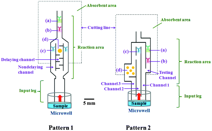 | ||
| Fig. 1 Schematic illustration of the automated paper-based device with 2 different designs for the sandwich ELISA. The prepared substances were included on the devices in (a) the control zone, which contained the immobilized Ab that picks up free (Ag unbound) enzyme-linked detection Ab to confirm that the test has operated correctly; (b) the test zone, which contained the immobilized Abs specific to the target Ag (forming a sandwich ELISA) and showed a colored band for positive test samples; (c) enzyme-linked detection antibody (the second antibody) that was allowed to bind to the antigen; and (d) substrate mixture that reacted with the enzyme label to generate the insoluble colored product. The outer shape of the device was cut from an NC membrane. | ||
For the first pattern, we made 2 types of channels (delaying and nondelaying) in the reaction area. The two channels had controlled differential reagent flow times and merged into 1 main channel towards the end of their path length. The delaying channel had special printing with a set of baffles to delay the flow of the solution into the prespotted substrate region. The nondelaying channel was used to guide the solution flow directly and immediately to the prespotted region of the enzyme-linked detection Abs.
The second pattern was designed with 3 separate channels in the reaction area with a different path length from the input “leg” to the test zone. The 3 channels included channel 1, where the sample solution flowed toward the testing channel, and channels 2 and 3, which were used to guide the solution flow to the prespotted region of the enzyme-linked detection Ab (enzyme-Ab2) and the substrate, respectively. Furthermore, we created a gap between channel 2 (below (c)) and channel 3 to guide the enzyme-Ab2 to migrate upward to the test zone and to prevent mixing of the enzyme-Ab2 and the substrate from the top of the channel 2 to the test zone.
For ELISA testing using automated paper-based devices, each reaction was run automatically after applying the sample solution to the device. Because of the delaying pattern, switching of the fluidic flow occurred at the test zone, allowing sequential reactions to occur. Switching of the flow obtaining from patterns 1 and 2 are schematically shown in Fig. 2. For pattern 1 (Fig. 2A), a 2-step reaction, including capture of enzyme-Ab2-Ag complexes and enzymatic reactions, was performed sequentially by a one-time switch of flow. In step 1, before the solubilized substrate (y) was rehydrated in the delaying channel, the sample fluid (s) that passed through pre-spot of the enzyme-Ab2 (x) migrated toward the test area, allowing enzyme-Ab2-Ag complexes be captured with the immobilized specific Ab1 at this area. In step 2, after the substrate (y) was rehydrated, the fluidic flow at the middle of test line was switched from the sample fluid containing the enzyme-Ab2 (x + s) to the sample fluid containing the substrate (y + s), which allowed the substrate react with the enzyme-Ab2. For pattern 2 (Fig. 2B), a 4-step process including the capture of Ag, capture of enzyme-Ab2, washing of unbound enzyme-Ab2, and enzymatic reactions, was performed sequentially by a 3-step switch. In step 1, the sample fluid (s) flow passed through test area. Thus, the (s) was captured and preconcentrated at the test zone. In step 2, after the membrane was fully wetted, the (x + s) migrated to the test zone at the left-hand side of the test. In Step 3, the (s) that has passed through the gap between channels 2 and 3 reached the (x + s); therefore, the (s) front moved to the test zone, allowing the unbound (x) to be washed away. In step 4, the (y) was rehydrated, and the front moved to the test area, permitting the flow pattern to change and switch from the sample (s) to the (y + s), thereby allowing the enzyme reaction occur at the left-hand side of the test zone. The sandwich ELISA procedure is schematically shown in Fig. S1† and summarized in ESI† section B.
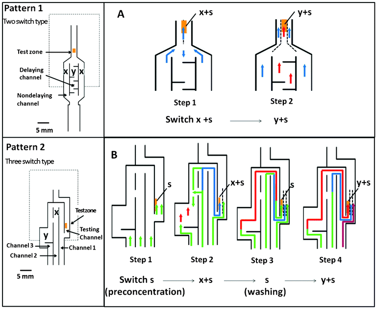 | ||
| Fig. 2 Schematic illustration of the automated paper-based device with 2 different designs: (A) pattern 1 and (B) pattern 2, and the switching of flow pattern. The green arrow represents the flow of sample (s); the blue arrow represents the flow of sample containing enzyme-Ab2 (x); the red arrow represents the flow of sample containing substrate (y). | ||
Fabrication of automated paper-based devices
The designed patterns were transferred to the inkjet software program for processing. The patterns were fabricated on the NC membrane using dipropylene glycol methyl ether acetate containing 20% acrylic polymer as the solvent ink with an SLT0505-HKF inkjet printing machine (SIJ Technology; Tsukuba, Japan). The outer rims of the device were cut by following the print line. The NC membrane (HF135MC100) was purchased from Nihon Millipore K.K. (Tokyo, Japan). The printed barrier width was quantified using a Digital HF microscope (VH8000C, Keyence Co., Japan). In the inkjet process, the surface of the NC membrane to be sprayed by solvent ink followed the patterned design that provided the barrier to create a hydrophilic channel. The width of the printed lines was based on the spreading of the solvent, which depended on solvent viscosity and various instrumental parameters, including the voltage supply, bias, frequency, and the gap between the tip and surface membrane; therefore, the optimal conditions for these parameters were determined. The resulting optimal instrument parameters for solvent ink printing on the NC membrane were set to control the barrier width.Chemicals
Monoclonal (m) mouse anti-human alpha subunit 6601SPR-5 (anti-hCGα mAb) and mouse anti-human chorionic gonadotropin (anti-hCG mAb) were purchased from Medix Biochemica (Kauniainen, Finland). Polyclonal (p) rabbit anti-mouse immunoglobulins (anti-mouse IgG pAb) were purchased from Dako Cytomation (Glostrup, Denmark). Alkaline phosphatase (ALP)-labeled anti-hCG (ALP-anti-hCG mAb) was prepared using an alkaline phosphatase-labeling kit purchased from Dojindo (Rockford, IL) according to the manufacturer's instructions.20 hCG was purchased from Rohto Pharmaceutical Co., Ltd. (Tokyo, Japan). The BCIP/NBT (5-bromo-4-chloro-3′-indolyphosphate p-toluidine salt, nitro-blue tetrazolium chloride) substrate solution and substrate buffer solution were obtained from Nacalai Tesque (Kyoto, Japan). Disodium hydrogen phosphate (Na2HPO4), sodium chloride (NaCl), potassium chloride (KCl), boric acid, casein, sodium dodecyl sulfate (SDS), and sucrose were purchased from Wako Pure Chemical Industries (Osaka, Japan). Bovine serum albumin (BSA) was purchased from Sigma Aldrich Japan (Tokyo, Japan). Analytical-grade reagents and 18 MΩ cm resistance water (obtained from a Barnstrad Milli-Q purification system) were used throughout this experiment.Preparation of reagents for the hCG ELISA
Briefly, the anti-hCGα mAb and the anti-mouse IgG pAb were prepared at 1 mg mL−1 in 50 mM phosphate buffered saline (PBS, pH 7.4) and subsequently mixed with 1% (w/v) sucrose solution in 50 mM Na2HPO4 (pH 7.5). The blocking solution was 50 mM boric acid buffer with 0.5% (w/v) casein, and the washing solution was 50 mM phosphate buffer (pH 7.5) with 0.01% (w/v) SDS. ALP-anti-hCG mAb was prepared at 25 μg mL−1 in 50 mM PBS (pH 7.5) containing 0.1% (w/v) BSA. The BCIP/NBT substrate was prepared in the substrate buffer solution (1![[thin space (1/6-em)]](https://www.rsc.org/images/entities/char_2009.gif) :10 dilution). Test sample solutions were prepared by dilution of the hCG solution with substrate buffer, and 100 μL of each solution was placed into the microwells for each experiment.
:10 dilution). Test sample solutions were prepared by dilution of the hCG solution with substrate buffer, and 100 μL of each solution was placed into the microwells for each experiment.
Preparation of the automated paper-based device for the one-step detection of hCG by ELISA
The scheme of the automated paper-based device for the sandwich ELISA was briefly described above and is shown in Fig. 1. For detection of hCG by ELISA, the anti-mouse IgG pAb and anti-hCGα mAb solutions (0.5 μL at 1 mg mL−1) were immobilized by application to the NC membrane in the control and test zones at locations (a) and (b), respectively. After drying for 1 h at room temperature, the NC membrane was blocked (against nonspecific protein adsorption) and washed by sequential immersion in blocking and washing solutions for 30 min each at room temperature, and the membrane was dried overnight. The ALP-anti-hCG mAb (0.5 μL at 25 μg mL−1) and the BCIP/NBT substrate (0.5 μL at 1:10 dilution) were spotted by hand onto the NC membrane at locations (c) and (d), respectively, and allowed to dry.
Data processing
Images of the paper-based device were captured using a digital camera (IXY200F, Canon, Japan, operated in automatic mode with no flash and using macro imaging settings). The signal measurement was taken at the test zone, and the background measurement was taken at the area just above the test zone in the same piece of the device. Then, the mean color intensity of the image at the selected area was quantified using the histogram function with the RGB channel in Adobe Photoshop CS3. The mean intensity values of each data point were obtained by background subtraction.Results and Discussion
Creating the barrier pattern in NC membranes using an inkjet printing method
In this work, the device was designed to use single fluid solubilized substances deposited on the membrane at different areas and to sequentially deliver the substances to the detection region. An inkjet printer was used to print the solvent ink onto the NC membrane to create the barrier line of the patterned devices. This inkjet dispensing system was resistant to the organic solvents used to create this line on the NC membrane. The quality of the printed line on the membrane was dependent on the adjustable instrumental parameters and the substrates (see ESI†, section C). The resulting optimal parameters for the NC membrane were set as follows: voltage supply = 1000 V, bias = 200 V, frequency = 300 Hz, and gap between the inkjet tip and surface paper = 250 μm. The barrier lines were printed at one time. After drying the solvent at room temperature, the pattern was imprinted on the device. The morphology of the printed line on the NC membrane was observed by scanning electron microscopy (SEM), where the cross-sectional images of the well-defined barrier structure on the NC membrane could be clearly seen (Fig. 3A). NC membranes are made of pure cellulose nitrate, and solutions can pass through the membrane pores by capillary action. By the inkjet printing method, ink is directly printed onto the surface of the membrane and penetrates the entire depth of the membrane layer. The organic solvent dissolves, damages, and shrinks the microporous membrane structure. Consequently, after evaporation of the solvent, the acrylic polymer is deposited with nitrocellulose at the surface of the support to make a tight layer. As a result, the solution cannot pass through the printed line, allowing it to act as a barrier area. The barrier quality was tested by applying 15 μL of Victoria blue B color solution (5 μg mL−1) in the middle of a 5 × 5 mm printed square area on the NC membrane, in which each square was printed with lines of different thickness (Fig. 3B). The results showed that the solutions were completely contained by the barrier without any leakage when the printed line width was at least 120 μm, but not with thinner lines. Based on these results, we concluded that the inkjet printing method using solvent ink enabled us to achieve a high quality barrier on the NC membrane. In addition, the inkjet printing method appeared to provide highly reproducible control of the amount of ink (based on a fixed set of printing parameters) and placement of the print. Therefore, this technique is applicable for fabricating such automated paper-based devices, using a very simple technique and allowing for the fabrication of design patterns on the NC membrane. The process included dissolving nitrocellulose and depositing the remaining acrylic polymer on the substrate, which may limit the amount of materials used. Therefore, this method should be applicable for the other types of porous material structures similar to nitrocellulose, such as filter paper.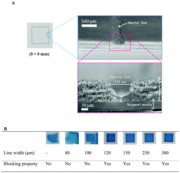 | ||
| Fig. 3 (A) SEM micrographs of the barrier line (in cross-sections) on the NC membrane, as fabricated by inkjet printing, and (B) images of the dye containment within a 5 × 5 mm printed square on the NC membrane printed with lines of different thicknesses. Images were taken 2 h after the application of 15 μL of Victoria blue B color dye solution (5 μg mL−1). | ||
The pattern design for creating delayed fluid flow on the NC membrane
Previous work reported the study of flow in paper networks in order to understand the principles of transport in paper for sequential delivery of multiple reagents.18,21 This basic background allowed us to predict the flow paths within our patterned design by changing path lengths to vary transport times on 1 piece of membrane. By trial and error, we found that controlling the fluidic flow times, flow directions, and spotted reagent locations on these paper-based devices played an important role in creating automated paper-based devices for sandwich ELISAs. Thus, we attempted to create a pattern with different path lengths from the sample inlet to the test zone in order to control the migration of the fluidic sample to sequentially pass through the dried dissolvable reagents deposited at different locations on the membrane (which must be located in a separate channel).To obtain an automated paper-based device for sandwich ELISA, the application of this delayed pattern was applied to the NC membrane to control the flow of reagents. The first pattern design was based on the migration time differences between fluids in the non-delaying and delaying channels using the set of baffle lines. Thus, the number of horizontal baffle lines required for delaying the fluid flow time in the delaying channel (20 × 3 mm; Fig. 4A) was evaluated in terms of the extra time taken for the solute in the delaying channel to reach the channel merge point compared with that in the nondelaying channel. We observed an almost linear delay with the increase in the number of printed baffles (Fig. 4B). Therefore, horizontal baffle lines can be used to delay the solution by providing a longer pathway in the same channel length. We chose an initial baffle and 5 additional baffles clustered together to delay the fluid in the first pattern (Fig. 4C). Although increasing the number of baffles was expected to increase the delay between the 2 substances arriving at the test zone, the color intensity of the results was not only reduced but also delayed the ELISA. For the second pattern design, a different channel with a different path length was created to control the arrival time of the individual substances to the test zone, thereby allowing for the automation of a multistep reaction sequence (Fig. 4D).
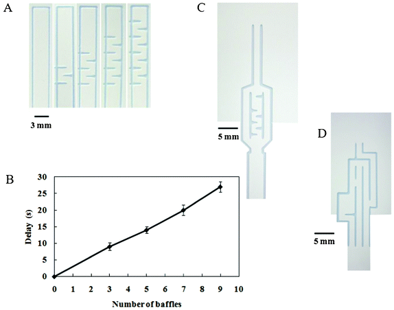 | ||
| Fig. 4 The design used to control solution flow and to achieve delayed flow. (A) The baffle design pattern printed on the paper-based device varied in number but not spacing, allowing delayed flow. (B) Correlation between the fluid delay and the number of printed horizontal baffle lines; data are derived from 3 repeats. (C) and (D) Photographs of the automated paper-based device made using patterns 1 and 2, respectively. | ||
Performance of the automated paper-based device for hCG detection by sandwich ELISA
The hCG protein was chosen as the model Ag (analyte) for the evaluation of this device because it is a realistic analyte for point-of-care detection. To obtain the highest sensitivity and reproducibility, analytical parameters, including the components and pH of the running buffer, the amount and concentration of the ALP-Ab2, and the BCIP/NBT substrates, were optimized. The optimal conditions that provided the highest intensity results at the test zone were then selected. The enzymatic reaction was optimal at the substrate kit buffer of pH 9, which was therefore used as the running buffer in this assay. ALP-Ab2 (0.5 μL at 25 μg mL−1) and 0.5 μL of the BCIP/NBT substrate diluted 1:10 (v/v) with the buffer were used.
In order to confirm the role of the delaying pattern, the hCG ELISA was investigated first by using the test strip without the delay line. Fig. 5A shows the structure of a strip used here. After dipping the strip into the sample solution, the analyte solution migrated forward along the membrane strip to the prespot region of the substrate, the ALP-Ab2, the immobilized Ab1 (test zone), and the immobilized anti-mouse IgG Ab (control zone), sequentially. The results of the hCG ELISA are shown in Fig. 5A. Color changes with 100, 200, and 500 ng mL−1 hCG were not found at the test zone. Thus, the strip was unsuccessful without a delaying pattern, and the delay line appeared to be essential for our design to work.
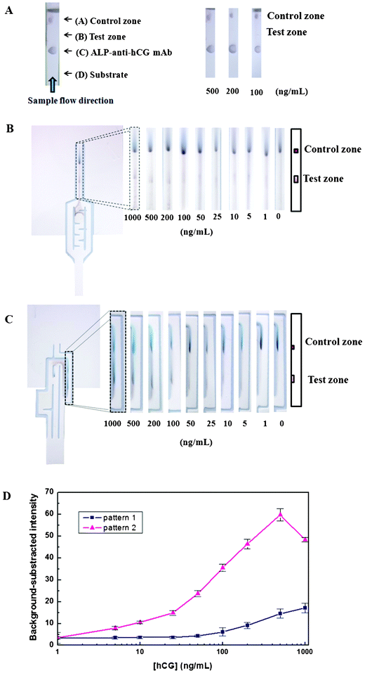 | ||
| Fig. 5 (A) Images of the hCG ELISA results on the test strip using 500, 200 and 100 ng mL−1 hCG without a delaying pattern. Images of the hCG ELISA results on the automated paper-based device made with pattern 1 (B) and pattern 2 (C). (D) The calibration curve of hCG from 1–1000 ng mL−1 in substrate buffer solution using patterns 1 and 2. The data are derived from 3 replicates. | ||
Fig. 5B and 5C show the results with delay lines added to patterns 1 and 2, respectively. Various concentrations of hCG from 1–1000 ng mL−1 were examined. After immersing the device in the analyte solution, the sample migrated following the flow pattern designed on the device. If hCG was present, a color change occurred at the test zone within 15 min for the first design pattern (pattern 1) and within 25 min for the second design pattern (pattern 2). At the test and control zone, the BCIP/NBT substrate reaction was catalyzed by the ALP enzyme, producing a purple color. Although the obtained product was not very soluble and precipitated, it was partially rehydrated and migrated, stretching out downstream from the test zone. However, we can negate this effect by limiting the detection area for data analysis to the selected high intensity area of the test zone. This stretching will be minimized by changing the substrate to a more insoluble product after the enzyme reaction. Since some of the ALP-Ab2 solution may stick to the membrane during migration along the channel, after the substrate flows to the upper region, the colored background will be generated. Furthermore, in pattern 1, since ALP-Ab2 solutions moved backward to the delaying channel, the substrate may react with this ALP-Ab2, also providing color. This drawback was minimized by pattern 2 in which ALP-Ab2, sample solution, and substrate were sequential, allowing the ALP-Ab2 to be washed out by sample solution. For both patterns, therefore, the background values obtained at the selected area above the test zone were subtracted from the colored signal values at the test zone.
The calibration curves comparing the results of hCG detection using different design patterns on our automated paper-based devices are shown in Fig. 5D. The background-subtracted intensity of the color obtained using pattern 1 was consistently below 25 ng mL−1 and increased as the hCG concentration increased above 25 ng mL−1. Using pattern 2, the background-subtracted intensity increased with increasing hCG concentration from 1 to 500 ng mL−1, but decreased with further increases in hCG concentration. This decrease was likely due to the shortage of free ALP-Ab2 at the test zone. Moreover, the hCG antigen in the sample may bind to not only Ab1, but also ALP-Ab2 at the pre-spot area. However, the colorimetric signal intensities at the test zone from pattern 2 were higher than the ones observed from pattern 1. The limits of detection (LODs) for hCG were 25.9 ng mL−1 (259 mIU mL−1) and 0.81 ng mL−1 (8.1 mIU mL−1) for patterns 1 and 2, respectively, calculated from the separate devices using 3-times the standard deviation (3σ) of the intensity of zero concentration (n = 7); therefore, pattern 2 was more sensitive than pattern 1. This increase in sensitivity occurred due to 2 main reasons: 1) the large amount of hCG that passed though the test zone before the substrate arrived in the test zone, allowing preconcentration of the sample, and 2) pattern 2 allowed the ALP-Ab2 to be washed out by sample solution, reducing the background signal.
Thus, the devices were able to allow the successful detection of hCG by automated paper-based ELISA. The current LOD for hCG is 8.1 mIU mL−1, which is lower than detectable levels of conventional pregnancy test strips (20–100 mIU mL−1). The LOD may be further improved by additional optimization. Our devices showed potential for the development of an automated paper-based (NC) quantitative ELISA detection system with a simple one-step manual operation, displaying ease of use and reducing both assay time and reagent consumption.
The devices presented here have some problems with the substances sticking on the membrane, which can lead to unwanted colored signals that affect the sensitivity of the device. However, this may be further improved in the near future by using modified paper-based materials or modified buffer solutions for preparation of substances.
Effects of the pattern design of the automated paper-based device on the sensitivity of the sandwich ELISA
To confirm the contribution of the pattern design to the one-step assay, the hCG ELISA was studied using the automated device (Fig. 6A) with different patterns: (I) pattern 1 without a separated channel or delaying pattern; (II) pattern 1 without a delaying pattern; (III) pattern 1 with a delaying pattern in 1 separated channel; (IV, V) pattern 2 with reduced path lengths between the applied reagents and test zone; (VI) pattern 2 without the gap between channels 2 and 3; and (VII) pattern 2.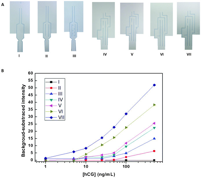 | ||
| Fig. 6 (A) Image of the paper-based devices using (I) pattern 1 without a separated channel or delaying channel; (II) pattern 1 without a delaying channel; (III) pattern 1 with a delaying channel; (IV, V) pattern 2 with a shorter distance between the substrate and ALP-anti-hCG mAb location and test zone; (VI) pattern 2 without a gap between channels 2 and 3, and (VII) pattern 2. (B) Plots of the mean color intensity of the hCG ELISA using the pattern formats described in (A) versus hCG concentrations from 1–500 ng mL−1. | ||
Fig. 6B shows the plot of the background-subtracted intensity values versus hCG concentrations in the range of 1–500 ppm, using the above-mentioned patterns. For pattern 1 (I), without the delaying pattern, colorimetric results could not be obtained. Additionally, the resulting color intensity and sensitivity were significantly greater for pattern 1 (III) than for pattern 1 (II) because the delay of the substrate by pattern 1 (II) was not enough to allow the first reaction to be completed. The hCG ELISAs using pattern 2 (IV), (V), (IV), and (VII), were also investigated. The color intensity at the test zone and the sensitivity of the assay decreased with decreasing distance between the spotted ALP-Ab2 and substrate location and the test zone. This was because the delay time for sequential reactions was reduced more by pattern 2 (IV) than by pattern 2 (V) and more by pattern 2 (V) than by pattern 2 (VII). Additionally, with decreased path lengths between spotting substances and the test zone, the distance between the bottom of the device and the testing channel was increased, which decreased the delay time required to pre-concentrate the antigen at the test zone. Lastly, the results obtained using pattern 2 with (VII) and without (VI) the gap between channels 2 and 3 were compared. The color intensity was slightly decreased by pattern 2 (VI) because the ALP-Ab2 and substrate mixed at the top of channel 2 in the pattern without the gap, resulting in a high background intensity at the test zone. However, the ALP-Ab2, sample solution, and substrate sequentially flowed without mixing with one another in pattern (VII). The LODs for hCG using patterns (II), (III), (IV), (V), (VI), and (VII) were 50, 26, 12, 9, 5, and 1 ng mL−1, respectively. These results provide the basic proof-of-concept design for this new inexpensive platform, which shows promise as an alternative device for future point-of-care monitoring.
Analytical application
The device with pattern 2 was evaluated for the determination of hCG using male and non-pregnant female clinical control urine samples (Lee Biosolution, Inc.). Different concentrations of hCG were spiked into the urine sample. Fifty microliters of substrate kit buffer was added into 50 μL urine, then the pH was adjusted to 9; the results are shown in Fig. S3†. The assay could detect hCG at a final concentration as low as 4 ng mL−1 (40 mIU mL−1). Thus, the devices developed herein were successfully applied to the determination of hCG in urine samples.Conclusions
New automated paper-based devices were developed to provide simple and rapid portable quantitative measurements in a sandwich ELISA format by changing both the pattern design and the spotted reagent locations on a piece of NC membrane. Only a single sample application was required for running the entire assay. The inkjet printing method enabled simple and low-cost fabrication of the printed baffles and channel lanes to direct the test analyte solution flow on the NC membrane. Therefore, this device has notably lower costs and can be mass-produced similar to other paper-based devices. Finally, the method developed herein has been successfully used for hCG ELISA in urine samples. We expect that the sensitivity of the device can be further improved and that this technology can be extended to a greater variety of clinical or environmental analytes.Acknowledgements
A.A. gratefully acknowledges the Thailand Research Fund through the Royal Golden Jubilee Ph.D. Program (Grant No. PHD/0256/2549). O.C. greatly thanks the Thailand Research Fund, the Thai Government Stimulus Package 2 (TKK2555), under the Project for Establishment of Comprehensive Center for Innovative Food, Health Products and Agriculture, Chulalongkorn University and the National Research University Project of CHE and Ratchadaphiseksomphot Endowment Fund (Project Code AM1009I).References
- T. T. Ngo and H. M. Lenhoff, Mol. Cell. Biochem., 1982, 44, 3–12 CrossRef CAS.
- S. Park, H. Kim, S. H. Paek, J. W. Hong and Y. K. Kim, Ultramicroscopy, 2008, 108, 1348–1351 CrossRef CAS.
- Y. K. Kim and H. Kim, J. Ind. Eng. Chem., 2009, 15, 229–232 CrossRef CAS.
- A. W. Martinez, S. T. Phillips, G. M. Whitesides and E. Carrilho, Anal. Chem., 2009, 82, 3–10 CrossRef.
- J. Wang, D. Johannsmann, M. Hollas and V. Thom, Desalination, 2006, 199, 232–233 CrossRef CAS.
- Y. Lu, W. Shi, J. Qin and B. Lin, Anal. Chem., 2009, 82, 329–335 CrossRef.
- W. Dungchai, O. Chailapakul and C. S. Henry, Anal. Chem., 2009, 81, 5821–5826 CrossRef CAS.
- C. D. Souza, O. C. Braga, I. C. Vieira and A. Spinelli, Sens. Actuators, B, 2008, 135, 66–73 CrossRef.
- D. A. Bruzewicz, M. Reches and G. M. Whitesides, Anal. Chem., 2008, 80, 3387–3392 CrossRef CAS.
- A. W. Martinez, S. T. Phillips, M. J. Butte and G. M. Whitesides, Angew. Chem., Int. Ed., 2007, 46, 1318–1320 CrossRef CAS.
- A. W. Martinez, S. T. Phillips, E. Carrilho, S. W. Thomas, H. Sindi and G. M. Whitesides, Anal. Chem., 2008, 80, 3699–3707 CrossRef CAS.
- K. Abe, K. Suzuki and D. Citterio, Anal. Chem., 2008, 80, 6928–6934 CrossRef CAS.
- Y. Lu, W. Shi, L. Jiang, J. Qin and B. Lin, Electrophoresis, 2009, 30, 1497–1500 CrossRef CAS.
- S. Wang, L. Ge, X. Song, J. Yu, S. Ge, J. Huang and F. Zeng, Biosens. Bioelectron., 2012, 31, 212–218 CrossRef CAS.
- C. M. Cheng, A. Martinez, J. Gong, C. Mace, S. Phillips, E. Carrilho, K. Mirica and G. Whitesides, Angew. Chem., Int. Ed., 2010, 49, 4771–4774 CrossRef CAS.
- E. Fu, B. Lutz, P. Kauffman and P. Yager, Lab Chip, 2010, 10, 918–920 RSC.
- E. Fu, P. Kauffman, B. Lutz and P. Yager, Sens. Actuators, B, 2010, 149, 325–328 CrossRef.
- K. Kerman, N. Nagatani, M. Chikae, T. Yuhi, Y. Takamura and E. Tamiya, Anal. Chem., 2006, 78, 5612–5616 CrossRef CAS.
- M. Elliott, A. Kardana, J. Lustbader and L. Cole, Endocrine, 1997, 7, 15–32 CrossRef CAS.
- Provider's instruction manual; http://www.dojindo.com/newimages/ALKTechnicalInformation.pdf.
- J. L. Osbon, B. Lutz, E. Fu, P. Kauffman, D. Y. Stevens and P. Yager, Lab Chip, 2010, 10, 2659–2665 RSC.
Footnote |
| † Electronic Supplementary Information (ESI) available. See DOI: 10.1039/c2lc40690j |
| This journal is © The Royal Society of Chemistry 2013 |