Highly sensitive stretchable transparent piezoelectric nanogenerators†
Received
18th September 2012
, Accepted 1st November 2012
First published on 1st November 2012
Abstract
Here we report a new type of stretchable transparent piezoelectric nanogenerator (NG) using an organic piezoelectric material consisting of poly(vinylidene fluoride trifluoroethylene) [P(VDF-TrFE)] sandwiched with mobility-modified chemical vapor deposition-grown graphene electrodes by ferroelectric polarization into P(VDF-TrFE). This new type of NG has a very high sensitivity and mechanical durability with fully flexible, rollable, stretchable, foldable, and twistable properties. We also investigated the mobility-modified graphene electrodes with ferroelectric P(VDF-TrFE) remnant polarization, and a mechanism is proposed for switching the mobility of the carriers by the ferroelectric remnant polarization. Upon exposure to the same input sound pressure, the measured output performance of the stretchable NG with a thin polydimethylsiloxane stretchable rubber template is up to 30 times that of a normal NG with a plastic substrate. Upon exposure to an air flow at the same speed, the measured output voltage from the stretchable NG is about 8 times larger than that of the normal NG.
Broader context
A stretchable transparent nanogenerator (NG) with a high sensitivity having a thin PDMS rubber template which acts as a stretchable mechanical spring is investigated based on the modification of the mobility of graphene electrodes by ferroelectric P(VDF-TrFE) remnant polarization. This new type of piezoelectric NG has stretchable, multi-shape transformable, and mechanically durable properties with a very high sensitivity. We demonstrate that upon their exposure to the same input sound pressure, the measured output performance of the stretchable NG is up to 30 times that of the normal NG and that upon their exposure to an air flow at the same speed, the measured output voltage from the stretchable NG shows a clear enhancement of up to about 8 times compared with that of the normal NG.
|
1 Introduction
The power generation performance and commercialization of piezoelectric power generators with a thick and rigid template are limited because they are usually operated in a low magnitude and frequency situation with very minute and irregular mechanical energy sources from the living environment, such as body movements, air flow, hydraulic pressure and acoustic vibrations, which are mostly of low magnitude and low frequency.1–10 In addition, they do not offer multifunctionality, such as a high power output performance, high sensitivity, full flexibility, stretchability, and multi-shape transformability. Therefore, developing piezoelectric energy harvesters with high performance, sensitivity and stretchability is extremely important, in order to convert the various kinds of mechanical energies available in nature into electricity for the realization of the independent, sustainable, and wireless operation of low power-consuming devices and systems in self-powered mode.11–20 Moreover, stretchable power generators can be easily transferred onto various kinds of fabrics including flags, clothes, gloves, etc.
The atomically layered structure of two-dimensional graphene sheets with high mechanical elasticity (elastic modulus of about 1 TPa) and high transparency can be used to prepare fully flexible and rollable transparent piezoelectric power generators. However, although large-scale graphene grown by the chemical vapor deposition (CVD) method shows outstanding uniformity and good electrical properties, the enhancement of the electrical mobility of CVD-based graphene is required for it to be used as an electrode material for highly sensitive stretchable transparent piezoelectric NGs.21 In this work, we report a new type of stretchable transparent piezoelectric NG using an organic piezoelectric material consisting of poly(vinylidene fluoride trifluoroethylene) [P(VDF-TrFE)] sandwiched with mobility-modified CVD-grown graphene electrodes by ferroelectric polarization into P(VDF-TrFE). This new type of NG has a very high sensitivity and mechanical durability with fully flexible, rollable, stretchable, foldable, and twistable properties.
2 Experimental section
To grow the graphene sheets, a Cu foil was placed in a rapid thermal CVD chamber and the temperature was increased from room temperature to 1000 °C with a 10 standard cubic centimeters per minute (sccm) flow of H2 (1 Torr). When the temperature reached 1000 °C, the Cu foil was annealed for 30 min to clean its surface by the reduction of copper(II) oxide and to grow the grain size. The synthesis of the graphene sheets was achieved with a mixture of CH4 (20 sccm) and H2 (10 sccm) for a growth time of 30 min (1 Torr). After the growth was completed, the gas supply was terminated and the chamber was cooled to below 100 °C at a cooling rate of 160 °C min−1. A solution of P(VDF-TrFE) (10 wt%) dissolved in N,N-dimethylformamide (DMF) solvent was spun on the graphene electrode to a layer thickness of 2 μm, followed by drying at 60 °C to remove the DMF solvent. Next, this layer was maintained at 140 °C for 2 h and then naturally cooled down to room temperature in a nitrogen atmosphere, in order to enhance the crystallinity of the β phase.
The electrical properties of graphene were measured using Hall Measurement systems (ECOPIA, HMS-3000). The sound wave was generated by a speaker using a function generator (Tektronix, AFG3021B). The magnitude of the generated sound wave was measured by a dB meter. The air flow consisted of nitrogen gas from a blowing gun. The speed of the air flow was measured by an anemometer. The device was placed on a rigid square hollow stand in front of the speaker and the blowing gun which were 1 cm apart. The performance of the power generators was measured using an oscilloscope (Tektronix, DPO5054) (see ESI, Fig. S1 for the experimental setup†).
3 Results and discussion
Fig. 1 shows a schematic illustration of the experimental procedures employed to integrate the stretchable NG. First, to prepare one electrode for the stretchable NG, a polydimethylsiloxane (PDMS) thin film was spin deposited on a copper (Cu) foil using spin coating at 3000 rpm for 60 s (Fig. 1a). Fig. 1a reveals a cross-sectional field-emission scanning electron microscopy (FE-SEM) image of the 20 μm thick PDMS thin film on the Cu foil. This PDMS thin film acts as a stretchable mechanical spring and a stretchable rubber template, enhancing the mechanical durability of the device. Then, the large-scale monolayer graphene grown on a Cu foil using the CVD method was transferred onto a PDMS/Cu foil using the well-known wet transfer method (Fig. 1b).22,23 The transfer process was iterated three times to make a more conductive graphene electrode.
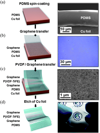 |
| | Fig. 1 Fabrication process of a stretchable NG (a) PDMS stretchable rubber template on the Cu foil, (b) transparent graphene sheet transferred to PDMS/Cu, (c) P(VDF-TrFE) and graphene sheet transferred to graphene/PDMS/Cu, and (d) stretchable NG with sandwiched graphene electrodes. | |
In a further step, a piezoelectric polymer thin film of P(VDF-TrFE) was spin-coated on a three-monolayer graphene sheet at 800 rpm for 60 s and subsequently annealed at 140 °C for 2 h. The FE-SEM image in Fig. 1c shows a typical P(VDF-TrFE) thin film morphology. To construct the stretchable NG, in the next step, the P(VDF-TrFE)/graphene sheet multilayer was transferred onto the graphene/PDMS/Cu foil template using a dry transfer method.24 Finally, the stretchable transparent NG was obtained by removing the Cu foil using a Cu etchant (Fig. 1d). The electrical poling process was carried out by applying an electric field between the top and bottom electrodes of graphene by applying an electric field of 100 MV m−1 for 30 min.
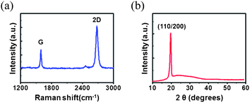
The Raman spectrum obtained from the graphene monolayer transferred onto SiO2 reveals no D band peak, indicating a low defect density in the graphene layer (Fig. 2a). The β-phase (110/200) formation in the P(VDF-TrFE) thin film was confirmed using synchrotron X-ray diffraction (XRD) measurements (Fig. 2b).25
The transparent, mechanically durable, and high carrier mobility properties of graphene made it a promising material for use as an electrode material for the stretchable NG in this work. Interestingly, it was found that the ferroelectric remnant polarization of P(VDF-TrFE) affects the electrical properties of the graphene sheet. The carrier type, carrier concentration, and mobility of graphene are investigated before and after poling at room temperature by Hall-effect measurements. The electrical properties of the three monolayer graphene sheet with non-poled P(VDF-TrFE) show p-type conduction with a carrier mobility of 748 cm2 V−1 s−1 and a sheet carrier density of 3.84 × 1013 cm−2. When the ferroelectric P(VDF-TrFE) is poled in both directions, it dopes the graphene with either electrons or holes. We observed the change of the charge carrier mobility in the graphene sheets depending on the direction of the applied electric field, as shown in Fig. 3a. On the application of an electric field of −100 MV m−1, the graphene sheets exhibited a carrier mobility of 822 cm2 V−1 s−1, which is approximately 10% higher than that of graphene with non-poled P(VDF-TrFE). On the other hand, on the application of an electric field of +100 MV m−1, the graphene sheets exhibited a carrier mobility of 665 cm2 V−1 s−1, which is approximately 10% lower than that of graphene with non-poled P(VDF-TrFE).
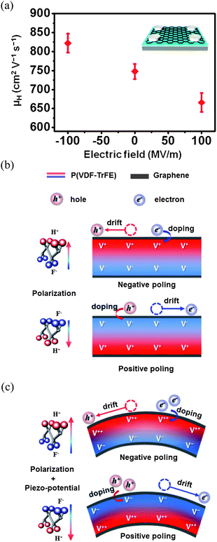 |
| | Fig. 3 (a) Carrier mobility of graphene sheets vs. the electric field applied to P(VDF-TrFE) in the poling process; the inset is a schematic of a sample prepared for Hall measurements. (b) Proposed mechanism for the carrier mobility switching of graphene when subjected to ferroelectric remnant polarization with negatively and positively poled P(VDF-TrFE). (c) Ferroelectric remnant polarization and piezoelectric effect with strain of P(VDF-TrFE). | |
Fig. 3b and c show the proposed mechanism for the carrier mobility switching of the graphene sheets according to the poling direction of P(VDF-TrFE). In general, non-poled ferroelectric materials, such as P(VDF-TrFE) in the pristine state, in which the molecular dipoles are randomly oriented, do not possess a net field due to their lack of polarization in any specific direction. Ferroelectric P(VDF-TrFE) is characterized by two symmetrical remnant polarizations, i.e. negative poling and positive poling for the upward and downward dipole configurations, respectively.26
As we discussed previously in Fig. 3a, the hole mobility of the graphene sheets increases and decreases upon negative and positive poling, respectively. In the polarized regime, the ferroelectric dipole charges are aligned along the direction of poling. Hence, the positive dipole charge (V+) and the negative dipole charge (V−) in P(VDF-TrFE) repel and attract holes in the p-type conducting graphene sheets, respectively. Therefore, the hole mobility increases, owing to the extra repulsive force exerted on the holes and decrease in the hole concentrations as a result of electrostatic doping of electrons with V+ upon negative poling, while V− reduces the hole mobility upon positive poling.27,28 On the other hand, the mobility of the electrons in graphene increases and decreases upon positive and negative poling, respectively, as shown in Fig. 3b. Further, as illustrated in Fig. 3c, it is expected that the remnant polarization will increase more when the P(VDF-TrFE) is subjected to tensile strain. Thus, the hole mobility upon negative poling further increases as compared to that upon positive poling in Fig. 3b, because of the stronger positive dipole charge (V++) originating from the tensile strain generated in the case of negative poling, while the stronger negative dipole charge (V−−) originating from the tensile strain increases the electron mobility in the case of positive poling.
As illustrated in Fig. 4a, in the graphene-sandwiched P(VDF-TrFE) structure, V+ repels holes and traps electrons at the top graphene sheet, while V− repels electrons and traps holes at the bottom graphene sheet. When the sandwiched structure is subjected to tensile strain, V−− drives the electron flow from the bottom graphene sheet to the top graphene sheet through an external load resistor, while V++ generates a flow of holes from the top graphene sheet to the bottom graphene sheet (Fig. 4b). Thus, the mobility of holes and electrons at both graphene sides is increased. Due to the large dielectric property of P(VDF-TrFE), the electrons (holes) accumulate at the interface region between the top (bottom) graphene sheet and P(VDF-TrFE). When the strain is released, the piezoelectric potential immediately vanishes and the accumulated electrons (holes) flow back through the external circuit, giving rise to opposite voltage and current pulses.
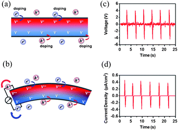 |
| | Fig. 4 Proposed mechanism for voltage and current output from the piezoelectric NG based on the graphene-sandwiched P(VDF-TrFE) structure. (a) and (b) are before and after applied strain, respectively. (c) and (d) are output voltage and output current density generated from the NG by bending (the strain of 0.081%), respectively. | |
We observed an output voltage of 8 V (peak-to-peak) with a current density of 0.8 μA cm−2 from a NG fabricated using graphene-sandwiched P(VDF-TrFE) with a 120 μm thick polyethylene naphthalate (PEN) substrate (Fig. 4c and d). By bending the device into an arc shape with a dimension as illustrated in Fig. 5, the strain in the length direction (εy) of the device is,
where
h is thickness of the device (120 μm, including the
polymer substrate because the strain is approximately equal to the strain of the outer surface of the
polymer substrate),
R is the bending radius that varies between 71.95 and 22.1 mm.
εy is 0.083–0.271%. With relation of Poisson's ratio (
ν,
ν = −
εx/
εy Poisson's ratio of P(VDF-TrFE) is 0.3), the strain in the thickness direction of the device is
εx = 0.025–0.081%. This result suggests that the
graphene-sandwiched P(VDF-TrFE) structure is a promising architecture for highly sensitive piezoelectric NGs.
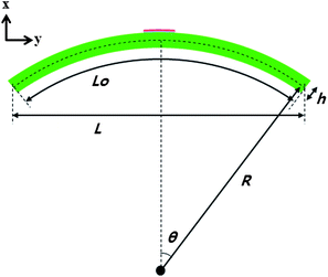 |
| | Fig. 5 Illustration of device bending to set up the strain. | |
In order to demonstrate the high sensitivity of the stretchable NG in a low magnitude and frequency situation with a very minute and irregular mechanical energy source, we compared this device with a normal NG with a plastic PEN substrate. Fig. 6a is an illustration of the stretchable NG and normal NG structures. When they are exposed to sound waves, the devices experience the sound pressure and, subsequently, a piezoelectric potential is generated across the thickness of P(VDF-TrFE). This generated piezoelectric potential drives the carriers from the electrodes to the external circuit; the output voltage and output current are measured from the stretchable NG and normal NG devices upon the application of various sound pressures. With the exposure of the devices to sound by varying the input powers from 82 to 110 decibels (dB) at 100 Hz, the measured peak to peak output voltage of the stretchable NG is from 50 mV to 600 mV, which shows a clear enhancement of about 30 times compared with that of the normal NG which is from 10 mV to 22 mV (Fig. 6b). We clearly observed a voltage output even upon the exposure of the stretchable NG device to sound waves with a low input power of 85 dB. On the other hand, we only observed noise signals upon the exposure of the normal NG to sound waves with an input power of 85–95 dB (Fig. 7). Hence, the clear observation of voltage output upon the exposure of the stretchable NG device to sound waves with a much lower input power confirms its high sensitivity in a low magnitude and frequency situation.
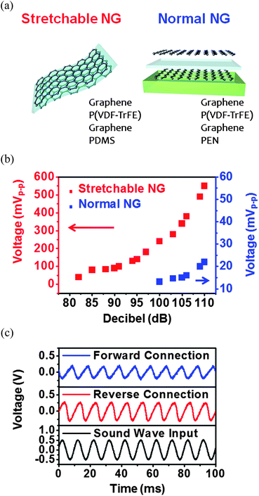 |
| | Fig. 6 (a) An illustration of the stretchable NG and normal NG structures. (b) Piezoelectric peak-to-peak output voltage generated from the stretchable NG and the normal NG under the same sound wave pressure. (c) Switching polarity test of voltage generated signals with an applied input sound wave. | |
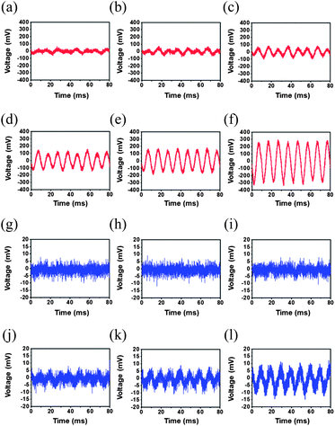 |
| | Fig. 7 Output voltages as a function of applied sound wave pressure (dB): (a) at 85 dB, (b) at 90 dB, (c) at 95 dB, (d) at 100 dB, (e) at 105 dB, and (f) at 110 dB on the stretchable NG; (g) at 85 dB, (h) at 90 dB, (i) at 95 dB, (j) at 100 dB, (k) at 105 dB, and (l) at 110 dB on the normal NG. | |
To verify that the measured signals were from the stretchable NG rather than the measurement system, a switching polarity test was performed, in which the electrodes were connected in reverse and the signals were also reversed. Moreover, a phase difference between the sound wave and the measured piezoelectric voltage signal due to the impedance of the intrinsic capacitance and the reactance within the piezoelectric circuit is observed (Fig. 6c). Also, the functional relationship of the parameters used in the sound-driven piezoelectric NGs can be described as
where
P,
V, and
f are the power (which is defined as the input intensity of the sound wave multiplied by the surface area), the output voltage obtained from the NG, and the frequency of the applied sound wave, respectively.
2 The output voltage obtained from the NG as functions of the input power of the applied sound wave at a fixed frequency of 100 Hz and the frequency of the applied sound wave at a fixed power at 100 dB are shown in
Fig. 8a and b respectively. At a constant frequency (100 Hz), the
V2 generated from the stretchable NG is proportional to the applied input sound intensity impacting on the stretchable NG. The
V2 generated from the stretchable NG increases linearly within the intensity range of 0–100 mW m
−2, which can be converted to power in the range of 0 to 10 μW considering the device size of 1 cm
2. When the input sound intensity was kept at ∼100 dB,
V2 was linearly dependent on the frequency of the applied sound wave. The measured output voltage signals of the stretchable NG depending on the frequency of the applied sound wave (100 Hz, 200 Hz, 400 Hz, and 800 Hz) are also shown in
Fig. 9. These relationships obviously provide evidence that the piezoelectric output is generated by the sound wave.
2
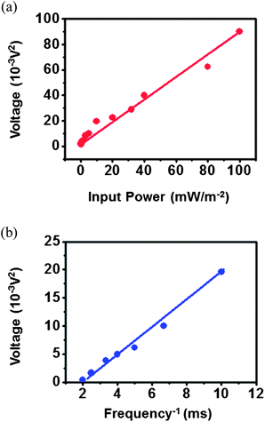 |
| | Fig. 8 (a) Output voltage vs. input power of the applied sound wave at a fixed frequency of 100 Hz. (b) Output voltage vs. frequency of the applied sound wave at a fixed power at 100 dB. | |
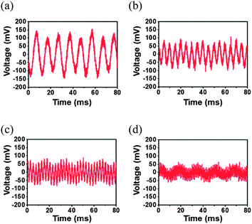 |
| | Fig. 9 Output voltage as a function of the frequency of the applied sound wave: (a) at 100 Hz, (b) at 200 Hz, (c) at 400 Hz, and (d) at 800 Hz on the stretchable NG. | |
We further demonstrate the wind-driven power-generating performance of the stretchable NG compared to the normal NG. The generated piezoelectric voltages are measured from stretchable NG and normal NG devices by varying the applied air flow pressure. Upon its exposure to an air flow, with speed varying from 0.5 m s−1 to 3 m s−1, the measured output voltage (peak to peak) from the stretchable NG ranges from 0.3 V to 3.9 V, while that from the normal NG ranges from 0.1 V to 0.5 V (Fig. 10a, b and 11). As clearly shown in Fig. 10b, the measured output voltage from the stretchable NG at 3.0 m s−1 is approximately 8 times larger than that from the normal NG at the same air flow speed of 3.0 m s−1. Interestingly, we observed different behavior in terms of the generated output voltages from the stretchable NG and the normal NG in response to the air flow. As shown in Fig. 10c, at a constant air flow with a speed of 3.0 m s−1, the stretchable NG produces a continuous output voltage owing to the vibration of the PDMS which acts as a stretchable mechanical spring. Similar behavior of piezoelectric output voltage signals generated from a PVDF microbelt has been demonstrated recently.5,6 On the other hand, we only observed an output voltage associated with noise from the normal NG during the application of a constant air flow between the turning on and turning off of the air flow due to the thick substrate (Fig. 10d).
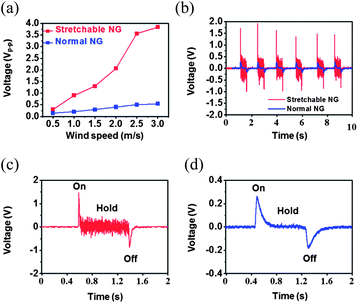 |
| | Fig. 10 (a) Output voltage generated from stretchable and normal NGs as a function of air flow speed. (b) Measured output voltage from stretchable and normal NGs at 3.0 m s−1. (c) and (d) show output voltage signals from stretchable and normal NGs, respectively, for one cycle between the turning on and turning off of the air flow (3.0 m s−1). | |
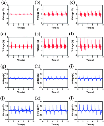 |
| | Fig. 11 (a) Output voltage as a function of the applied air flow speed: (a) at 0.5 m s−1, (b) at 1.0 m s−1, (c) at 1.5 m s−1, (d) at 2.0 m s−1, (e) at 2.5 m s−1, and (f) at 3.0 m s−1 on the stretchable NG; (g) at 0.5 m s−1, (h) at 1.0 m s−1, (i) at 1.5 m s−1, (j) at 2.0 m s−1, (k) at 2.5 m s−1, and (l) at 3.0 m s−1 on the normal NG. | |
4 Conclusions
In summary, a stretchable transparent NG with a high sensitivity having a thin PDMS rubber template which acts as a stretchable mechanical spring is investigated based on the modification of the mobility of graphene electrodes by ferroelectric P(VDF-TrFE) remnant polarization. This new type of piezoelectric NG has stretchable, multi-shape transformable, and mechanically durable properties with a very high sensitivity. We demonstrated that upon its exposure to the same input sound pressure, the measured output performance of the stretchable NG is up to 30 times that of the normal NG and upon exposure to an air flow at the same speed, the measured output voltage from the stretchable NG shows a clear enhancement of up to about 8 times compared with that of the normal NG. We believe that the approach described herein involving the fabrication of a stretchable NG with graphene electrodes is very promising for harvesting electrical energy from very minute and irregular mechanical energy sources in a living environment, such as body movements, air flow, and acoustic vibrations of low magnitude and low frequency.
Acknowledgements
This work was financially supported by the National Research Foundation of Korea (NRF) grant funded by the Ministry of Education, Science and Technology (MEST) (2012R1A2A1A01002787 and 2010-0015035), the Fusion Research Program for Green Technologies through the NRF funded by the MEST (2010-0019086), and the Energy International Collaboration Research & Development Program of the Korea Institute of Energy Technology Evaluation and Planning (KETEP) funded by the Ministry of Knowledge Economy (MKE) (2011-8520010050).
Notes and references
- Z. Li, R. Yang, A. C. Wang and Z. L. Wang, Adv. Mater., 2010, 22, 2534 CrossRef CAS.
- S. N. Cha, J.-S. Seo, S. M. Kim, H. J. Kim, Y. J. Park and S.-W. Kim, Adv. Mater., 2010, 22, 4726 CrossRef CAS.
- Z. Li and Z. L. Wang, Adv. Mater., 2011, 23, 84 CrossRef CAS.
- C. Chang, V. H. Tran, J. Wang, Y.-K. Fuh and L. Lin, Nano Lett., 2010, 10, 726 CrossRef CAS.
- C. Sun, J. Shi, D. J. Bayerl and X. Wang, Energy Environ. Sci., 2011, 4, 4508 CAS.
- X. Wang, Nano Energy, 2012, 1, 13 CrossRef.
- D. H. Choi, K. Y. Lee, M. J. Jin, S. G. Ihn, S. Y. Yun, X. Bulliard, W. Choi, S. Y. Lee, S.-W. Kim, J. Y. Choi, J. M. Kim and Z. L. Wang, Energy Environ. Sci., 2011, 4, 4607 CAS.
- K. Y. Lee, B. Kumar, J.-S. Seo, K.-H. Kim, J. I. Sohn, S. N. Cha, D. Choi, Z. L. Wang and S.-W. Kim, Nano Lett., 2012, 12, 1959 CrossRef CAS.
- M.-Y. Choi, D. Choi, M.-J. Jin, I. Kim, S.-H. Kim, J.-Y. Choi, S. Y. Lee, J. M. Kim and S.-W. Kim, Adv. Mater., 2009, 21, 2185 CrossRef CAS.
- S. N. Cha, S. M. Kim, H. J. Kim, J. Y. Ku, J. I. Sohn, Y. J. Park, B. G. Song, M. H. Jung, E. K. Lee, B. L. Choi, J. J. Park, Z. L. Wang, J. M. Kim and K. Kim, Nano Lett., 2011, 11, 5142 CrossRef CAS.
- X. Chen, X. Xu, N. Yao and Y. Shi, Nano Lett., 2010, 10, 2133 CrossRef CAS.
- Y. Qi, N. T. Jafferis, K. Lyons Jr, C. M. Lee, H. Ahmad and M. C. McAlpine, Nano Lett., 2010, 10, 524 CrossRef CAS.
- X. Chen, S. Xu, N. Yao, W. H. Xu and Y. Shi, Appl. Phys. Lett., 2009, 94, 253113 CrossRef.
- B. J. Hansen, Y. Liu, R. Yang and Z. L. Wang, ACS Nano, 2010, 4, 3647 CrossRef CAS.
- Z. Wang, J. Hu, A. P. Suryavanshi, K. Yum, M. F. Yu and Z. Y. Wang, Nano Lett., 2007, 7, 2966 CrossRef CAS.
- K.-I. Park, S. Xu, Y. Liu, G.-T. Hwang, S.-J. L. Kang, Z. L. Wang and K. J. Lee, Nano Lett., 2010, 10, 4939 CrossRef CAS.
- H.-K. Park, K. Y. Lee, J.-S. Seo, J.-A. Jeong, H.-K. Kim, D. Choi and S.-W. Kim, Adv. Funct. Mater., 2011, 21, 1187 CrossRef CAS.
- B. Kumar, K. Y. Lee, H.-K. Park, S. J. Chae, Y. H. Lee and S.-W. Kim, ACS Nano, 2011, 5, 4197 CrossRef CAS.
- K.-H. Kim, K. Y. Lee, J.-S. Seo, B. Kumar and S.-W. Kim, Small, 2011, 7, 2577 CrossRef CAS.
- M. Riaz, J. Song, O. Nur, Z. L. Wang and M. Willander, Adv. Funct. Mater., 2011, 21, 628 CrossRef CAS.
- S. Bae, H. Kim, Y. Lee, X. Xu, J.-S. Park, Y. Zheng, J. Balakrishnan, T. Lei, H. Ri Kim, Y. I. Song, Y.-S. Kim, K. S. Kim, B. Ozyilmaz, J. H. Ahn, B. H. Hong and S. Iijima, Nat. Nanotechnol., 2010, 5, 574 CrossRef CAS.
- A. Reina, X. Jia, J. Ho, D. Nezich, H. Son, V. Bulovic, M. S. Dresselhaus and J. Kong, Nano Lett., 2009, 9, 30 CrossRef CAS.
- X. Li, Y. Zhu, W. Cai, M. Borysiak, B. Han, D. Chen, R. D. Piner, L. Colombo and R. S. Ruoff, Nano Lett., 2009, 9, 4359 CrossRef CAS.
- Y. Lee, S. Bae, H. Jang, S. Jang, S. Zhu, S. Sim, Y. I. Song, B. H. Hong and J. H. Ahn, Nano Lett., 2010, 10, 490 CrossRef CAS.
- H. Ohigashi, K. Omote and T. Gomyo, Appl. Phys. Lett., 1995, 66, 3281 CrossRef CAS.
- Y. Zheng, G.-X. Ni, C.-T. Toh, M.-G. Zeng, S.-T. Chen, K. Yao and B. Ozylimaz, Appl. Phys. Lett., 2009, 94, 163505 CrossRef.
- A. K. Geim and K. S. Novoselov, Nat. Mater., 2007, 6, 183 CrossRef CAS.
- G.-X. Ni, Y. Zheng, S. Bae, C. Y. Tan, O. Kahya, J. Wu, B. H. Hong, K. Yao and B. Ozyilmaz, ACS Nano, 2012, 6, 3935 CrossRef CAS.
Footnote |
| † Electronic supplementary information (ESI) available: An illustration of the experimental setup. See DOI: 10.1039/c2ee23530g |
|
| This journal is © The Royal Society of Chemistry 2013 |
Click here to see how this site uses Cookies. View our privacy policy here. 
