3D carbon based nanostructures for advanced supercapacitors
Hao
Jiang
ab,
Pooi See
Lee
b and
Chunzhong
Li
*a
aKey Laboratory for Ultrafine Materials of Ministry of Education, School of Materials Science and Engineering, East China University of Science & Technology, Shanghai 200237, China. E-mail: czli@ecust.edu.cn; Fax: +86-21-6425-0624; Tel: +86-21-6425-0949
bSchool of Materials Science and Engineering, Nanyang Technological University, Singapore 639798, Singapore
First published on 12th October 2012
Abstract
Supercapacitors have attracted intense attention due to their great potential to meet the demand of both high energy density and power density in many advanced technologies. Various carbon-based nanocomposites are currently pursued as supercapacitor electrodes because of the synergistic effect between carbon (high power density) and pseudo-capacitive nanomaterials (high energy density). This feature article aims to review most recent progress on 3D (3D) carbon based nanostructures for advanced supercapacitor applications in view of their structural intertwinement which not only create the desired hierarchical porous channels, but also possess higher electrical conductivity and better structural mechanical stability. The carbon nanostructures comprise of CNTs-based networks, graphene-based architectures, hierarchical porous carbon-based nanostructures and other even more complex carbon-based 3D configurations. Their advantages and disadvantages are compared and summarized based on the results published in the literature. In addition, we also discuss and view the ongoing trends in materials development for advanced supercapacitors.
 Hao Jiang | Hao Jiang received his PhD degree in Materials Science and Engineering under the supervision of Prof. Chunzhong Li from East China University of Science & Technology (ECUST), China, in 2009. He is now an associate professor in Key Laboratory for Ultrafine Materials of Ministry of Education, ECUST. His current research interests include the design and development of carbon-based nanocomposites and their applications in energy storage devices. |
 Pooi See Lee | Pooi See Lee is Associate Professor and the Associate Chair in Research at the School of Materials Science and Engineering, Nanyang Technological University (NTU). She obtained her Ph.D. degree at the National University of Singapore in 2002. Her research includes fundamental and applications of nanostructures and nanocomposites, with emphasis on electrochemical devices such as energy storages and electrochromics, and nanoelectronic devices including memory, nanowire sensors and photodetectors. She was awarded the Norman Hackerman Young Author Award in 2002, Tan Chin Tuan Exchange Fellowship in 2005, and Fellow at the Hanse-Wissenshaftskolleg Institute of Advanced Study in 2010. |
 Chunzhong Li | Chunzhong Li received his PhD degree from East China University of Science and Technology in 1997. He became Full Professor at the School of Materials Science and Engineering in 1998, and now he is the director of the Key Laboratory for Ultrafine Materials of the Ministry of Education at East China University of Science and Technology. In 2009, he became the winner of the National Science Fund for Distinguished Young Scholars. His research interests include functionalization and fabrication of nanomaterials for applications in catalysis, clean energy and biomedicine. |
Broader contextSupercapacitors are one of the crucial devices for energy storage applications as they can provide higher power density than batteries and higher energy density than conventional dielectric capacitors. Many materials have been investigated as electrode materials for supercapacitors. Among them, carbon materials with various microtextures are considered as the main candidate for supercapacitors in terms of high surface area, interconnected pore structure, controlled pore size, high electrical conductivity and environmental friendliness. Nevertheless, pure carbon materials encounter difficulties in meeting the requirements of high energy storage devices even with the fine-tuned pore structures due to their energy storage mechanism which is a purely physical process. To further improve the energy density of supercapacitors without sacrifice of power density, carbon-based composites combining electrical double layer capacitance and pseudo-capacitance have been extensively explored, demonstrating enhanced capacitance as well as good cycling stability. In this review, recent progress on the 3D carbon based nanostructures encompassing the CNTs-based networks, graphene-based architectures, hierarchical porous carbon-based nanostructures and even more complex carbon-based 3D configuration for advanced supercapacitor applications is summarized, shedding light on their structural interconnectivities, which not only create hierarchical porous channels, but also lead to higher electrical conductivity and better structural mechanical stability. Their advantages and disadvantages are discussed, new trends of electrode materials for high-performance supercapacitors are also proposed. |
1. Introduction
The development of energy storage systems (ESSs) is critical for addressing the problems of climate change, the limited availability of fossils fuels, and also plays a key role for the efficient storage of solar and wind energy.1–6 In this regard, one of the greatest challenges facing current researchers is to construct highly efficient, low cost, and environmentally benign ESS devices. With a fast-growing market for portable electronic devices and the development of hybrid electric vehicles, there has been an ever-increasing demand for high energy and power densities energy storage devices. The stored energy should be able to be released smoothly and delivered even under a higher power density.2,7 Among the various ESSs, supercapacitors, also known as electrochemical capacitors or ultracapacitors, are projected to be the best potential candidate to meet the above requirements because of their high specific power (>10 kW kg−1), fast charge–discharge processes (within seconds), and long cycle life (>105).3,6–9 Until now, supercapacitors have been widely applied in consumer electronics, energy management, memory back-up systems, industrial power and mobile electrical systems.8,10 A typical example is the use of supercapacitors in the emergency doors on Airbus A380 (16 per plane), where the need for large scale implementation is also clearly proven. Furthermore, supercapacitors, coupled with high energy batteries or fuel cells in hybrid electric vehicles, can serve as temporary energy storage devices for power applications including electric braking assistance, starter and generators, exhibiting huge potentials for future EESs.11,12Supercapacitors can be divided into two categories depending on the energy storage mechanism:13 the electrical double layer capacitors (EDLCs), where capacitance arises from the pure electrostatic charges accumulated at the electrode–electrolyte interface, such as carbon materials; and the pseudocapacitors, in which fast and reversible oxidation/reduction (redox) or Faradaic charge reactions of the electroactive species take place on the surface of the electrode, such as metal oxides and conductive polymers. It is obvious that both EDLCs and pseudocapacitors are surface phenomena during the charge–discharge processes, and hence the performance greatly depends on the surface area. In general, a larger surface area is desired to achieve higher capacitance. Nevertheless, proper control over the specific surface area and the corresponding pore size of electrode materials is crucial because high microporosity will lead to a dramatic drop of capacitance at large current density.
Regardless of the type of the charge storage mechanism, the electrochemical performance is mainly determined by the adopted electrode materials. It is well-known that carbon-based materials are the most common electrode materials due to their intriguing properties including low cost, easy availability, nontoxic nature, environmental friendliness and stability.14–16Table 1 shows some examples of different carbon structures that can be used in EDLCs, including onion-like carbon (OLC), carbon nanotubes (CNTs), graphene, activated carbon (AC), carbide-derived carbon, and templated carbon.11 Each type of carbon structure has its pros and cons. For example, OLCs are be fully accessible to ion adsorption with excellent conductivity, resulting in high power performance but limited capacitance of ∼30 F g−1.17 CNTs are evaluated as electrodes to increase the energy density considering their unique tubular porous structures and superior electrical properties, which favor fast ion and electron transportation.18 However, the high production costs limit their widespread applications. More recently, graphene has attracted great interest for EDLC applications.19,20 As a 2D carbon nanostructure, graphene can potentially combine the advantages of providing a ully accessible high surface specific area and high conductivity. However, a key issue is how to avoid the restacking of sheets during electrode preparation. 3D (3D) hierarchical carbon materials (e.g. activated carbon, carbide-derived carbon and templated carbon) with high surface areas and rich pore structures are extensively tested for EDLCs.3 Their specific capacitance is unsatisfactory at a high current density due to the presence of micropores and relative low conductivity. Therefore, it is important to construct novel architectures by coupling the advantages of different carbon materials. To further enhance their energy density without the sacrifice of power density, carbon incorporated high energy electrode materials, such as transition metal oxides and conductive polymers, are also extensively explored to meet the requirements of high energy storage devices.11,16,21 In this context, carbon materials have at least dual functions, they not only contribute to the high capacitance of the composites, but can also serve as a conductive path for electron transport due to its high conductivity.
| Material | Carbon onions | Carbon nanotubes | Graphene | Activated carbon | Carbide derived carbon | Templated carbon |
|---|---|---|---|---|---|---|
| Dimensionality | 0D | 1D | 2D | 3D | 3D | 3D |
| Conductivity | High | High | High | Low | Moderate | Low |
| Volumetric capacitance | Low | Low | Moderate | High | High | Low |
| Cost | High | High | Moderate | Low | Moderate | High |
| Structure |

|

|

|

|

|

|
Currently, 3D carbon-based nanostructures is a new hot topic for high-performance supercapacitors.22–24 Due to the structural interconnectivities, 3D carbon-based nanostructures not only create hierarchical porous channels, but also possess a higher electrical conductivity and maintain better structural mechanical stability. The design and optimization of 3D carbon-based nanostructures are definitely important since each of the respective building block's properties can be dramatically enhanced if an appropriate nanostructure is chosen. In this review, a brief summary of a recent research progress on 3D carbon-based electrode materials is presented, mainly including CNTs-based networks, graphene-based architectures, hierarchical porous carbon-based nanostructures and even more complex carbon-based 3D configurations, as shown in Fig. 1. Their advantages and disadvantages are compared and summarized according to the available literature to date. In addition, new trends in materials development have also been proposed.
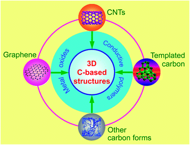 | ||
| Fig. 1 3D carbon based nanostructures from different forms of carbon and their combination with pseudo-active materials. | ||
2. Carbon nanotubes based networks
CNTs, which are well-known for their high conductivity and unique mechanical properties, have been extensively studied for EDLC applications within the past decade.7,20,24 It is well-accepted that CNTs are a good choice as high power electrode materials attributed to their high mechanical resilience and open tubular network, which render them as good support for other active materials. Owing to the above unique merits, CNT-based nanomaterials have been intensively investigated for electrochemical energy storage devices. However, major limitation is their relatively small specific surface area (generally <500 m2 g−1) as compared to activated carbon, which restricts their usage in high energy EDLCs. The high cost as well as purification difficulty also hinder their further practical applications. Therefore, modifications and incorporation with other active materials have been proposed to overcome the above drawbacks.2.1. Modification of carbon nanotubes
There are plenty of ways to modify CNTs in order to improve the manipulation of CNTs for the construction of high performance CNTs-based electrode materials, mainly including two categories: the covalent attachment of chemical groups,25–27 and noncovalent adsorption or wrapping of various functional molecules.28 For example, Niu et al.25 have reported a CNTs electrode pretreated in nitric acid showing an enhanced specific capacitance of 102 F g−1 with a surface area of 430 m2 g−1 in acidic electrolyte. The porosity of CNT can be further created through oxidation, resulting in a very high surface area of over 2200 m2 g−1.26 Although the electrochemical performance of CNTs was improved by the above methods, it is still difficult for pure carbon materials to meet the requirements of high energy density in view of their energy storage mechanism relying solely on the physical process. It is urgent to develop novel electrode materials that possess higher energy density without the sacrifice of power density. One effective way is by the modification of CNTs with pseudocapacitive active materials (i.e. metal oxides, conductive polymers) to realize pseudocapacitance by faradic processes.29–35 For example, Kim et al.29 reported the synthesis of well-dispersed hydrated RuO2 nanoparticles on carboxylated CNTs by the bond formation between RuO2 and the surface carboxyl groups of CNTs, showing an enhanced electrochemical performance. Zhang et al.30 investigated the supercapacitive performances of Co–Al layered double hydroxide (LDH) mixed with MWCNTs. The results show that the composites have higher specific capacitance (342 F g−1) with superior cycling stability than the pure LDH electrode (192 F g−1), which can be attributed to the network of MWCNTs attached to the surface of LDH, greatly enhancing the attachment of Co–Al LDH nanoparticles. It is concluded that introducing pseudocapacitive materials on the surface of carbon materials can efficiently improve the electrode's capacitance due to the synergistic effect between them.In general practice, the electrode materials powder will be mixed with some binding additives to form a paste, and then coated on a current collector for evaluation of their electrochemical performance.6,36 The addition of polymer binder will inevitably increase the “dead volume” in electrode materials. In comparison with CNTs powder, carbon nanotube arrays possess more regular pore structures and conductive paths, as shown in Fig. 2. More significantly, there is no need for extra binders or conductive additives. As mentioned above, materials based on EDLC mechanism have limited the specific capacitance. Analogously, by introducing pseduocapacitive materials into the 3D network, a synergistic effect between them will greatly enhance the electrochemical performance. For example, Zhang et al.37,38 have reported the use of a carbon nanotube array (CNTA) framework, which is directly grown on the current collector (Ta foil) as the support to construct manganese oxide–CNTA and PANI–CNTA composite electrodes with hierarchical porous structures, respectively. The electrochemical results indicated that a very high specific capacitance of 1030 F g−1 was achieved for PANI–CNTA composites with superior rate capability (95% capacity retention at 118 A g−1), and high cycling stability (only 5.5% capacity loss after 5000 cycles) in 1 M H2SO4 electrolyte.37 The manganese oxide–CNTA composites also possessed high rate capability (50.8% capacity retention at 77 A g−1, high specific capacitance (199 F g−1 and 305 F cm3) and a long cycle life (only 3% capacity loss after 20![[thin space (1/6-em)]](https://www.rsc.org/images/entities/char_2009.gif) 000 charge–discharge cycles), as shown in Fig. 3(a–c).38 Such intriguing capacitive performance can be mainly attributed to the superior conducting network consisting of CNTs, as well as the pseudocapacitive behavior of the well-dispersed active materials. The corresponding energy storage characteristics are illustrated in Fig. 3(d). However, the high cost of preparing such sophisticated networks is a concern.
000 charge–discharge cycles), as shown in Fig. 3(a–c).38 Such intriguing capacitive performance can be mainly attributed to the superior conducting network consisting of CNTs, as well as the pseudocapacitive behavior of the well-dispersed active materials. The corresponding energy storage characteristics are illustrated in Fig. 3(d). However, the high cost of preparing such sophisticated networks is a concern.
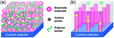 | ||
| Fig. 2 Schematic representation of transportation of electrons and electrolyte ions of electrodes (a) coating on the current collector and (b) directly grown on the current collector, respectively. | ||
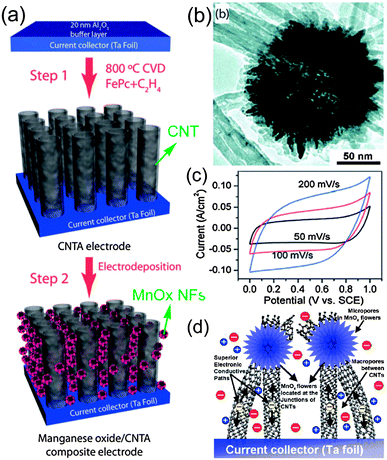 | ||
| Fig. 3 (a) Procedure for the preparation of manganese oxide–CNTA composite electrode; (b) TEM image of the manganese oxide nanoflowers; (c) CV curves of the manganese oxide–CNTA composite electrode; (d) the corresponding energy storage characteristics. Reprinted from ref. 38 with permission. | ||
In order to achieve both high power and energy densities, an optimal balance between the surface area and pore size distribution should be considered for carbon-based materials.8,39 As for CNTs, the generation of the porous tube wall still remains a challenge in view of their relatively smooth graphitic surface. Recently, another carbon structure, mesoporous carbon nanotubes (MCNTs), prepared with dopamine as a carbon source, has attracted considerable attention due to its tunable pore structure and the degree of graphitization, as shown in Fig. 4.40–42 The pore size distribution can be tuned in a certain range simply by changing the P123 concentration. The MCNTs, when applied as supercapacitor electrodes in 1 M H2SO4, demonstrated high specific capacitance (249 F g−1 at 0.5 A g−1) and rate capability (∼75% capacity retention at 20 A g−1), which are better than most of the reported CNTs.40 Instead of CNTs, the intriguing MCNTs are not only good electrode materials, but can also be used as excellent support to construct hybrid electrodes with optimized configurations,10,41 such as 3D architectures, even more complex structures for high performance supercapacitor applications.
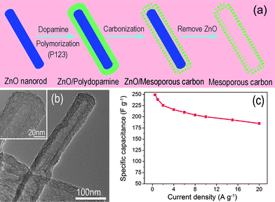 | ||
| Fig. 4 (a) Procedure for the preparation and (b) TEM image of mesoporous carbon nanotube; (b) specific capacitance of MCNTs versus different discharge current density. Reprinted from ref. 40 with permission. | ||
2.2. CNTs based weaves
Besides the combination of CNTs with pseudo-capacitive materials, another feasible approach is to make the 1D pseudo-capacitive materials and CNTs weaving in and out of each other, forming a 3D network for high-performance supercapacitors. It is well-known that transition metal oxides possess the advantages of low cost, environmentally friendly and high specific capacitance, and hence, they have been considered as one of the most promising materials for next generation supercapacitors.43–45 However, poor conductivity has limited their practical applications in energy storage devices. Although one-dimensional nanostructures have been designed to achieve fast redox reactions, high specific surface area and short diffusion paths for electrons and ions, the conductivity is still unable to meet the requirements of high-power supercapacitors. Utilizing the high conductivity and flexibility of CNTs, the weave-like network between CNTs and transitional metal oxides is expected to overcome the limitation. Yan et al.46 have prepared CuO nanobelts mixed with CNTs in an appropriate ratio, which showed high energy density of 130.2 W h kg−1 at 1.25 kW kg−1 with stable cycling performance. Recently, a class of supercapacitor electrode materials composed of interpenetrating networks of CNTs and V2O5 nanowires has been developed by Lu et al.47–49 As illustrated in Fig. 5(a), the interpenetrating structure creates hierarchical interconnected pore channels which are filled by the electrolyte, hence ensuring effective ion transport and redox active-site accessibility (i.e., high energy density).47 Furthermore, the building blocks composed of small dimension nanowires shorten ion diffusion paths, leading to better utilization of metal oxides. On the other hand, the metal oxide nanowires are intimately intertwined with highly conductive CNTs, forming a 3D conductive network, and hence ensuring faster electron transport and more efficient current collection (i.e. high power density). In view of these advantages, CNTs–V2O5 nanowire composite was successfully prepared by a simple hydrothermal route.48Fig. 5(b) shows a representative SEM image of the intertwined CNTs and V2O5 network with 18 wt% CNTs. The CNTs–V2O5 network shows excellent performance compared with the pristine V2O5 nanowires and CNTs, as shown in Fig. 5(c). Asymmetric supercapacitors were also assembled using CNTs–V2O5 as an anode and a commercial AC as the cathode material, as shown in Fig. 5(d), exhibiting energy density as high as 40 W h kg−1 at a power density of 210 W kg−1. Even at a high power density of 6300 W kg−1, the device also has an energy density of nearly 7.0 W h kg−1. These works demonstrate that rational design and synthesis of CNTs-based composite is an effective strategy towards high energy and power density supercapacitors.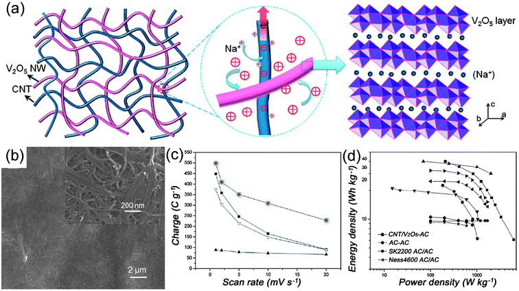 | ||
| Fig. 5 (a) Schematic of a nanocomposite consisting of interpenetrating networks of V2O5 nanowires and CNTs, the intimate contacts between them, and Na+ intercalation within the V2O5 layer structure, reprinted from ref. 47 with permission; (b) SEM images of the CNTs–V2O5 composites with 18 wt% of CNTs; (c) comparison of the rate capability of CNTs–V2O5 composites (●), V2O5 nanowires (■), CNTs (▲), and total charge storage by simply adding the capacity contribution of each constituent of the composite electrode (▼); (d) Ragone plots of an asymmetric supercapacitor made from activated carbon (AC) cathode and CNT–V2O5 nanocomposites anode, a symmetric supercapacitor made from the same AC, and various supercapacitor types developed recently. All data are based on the mass of the electrode materials. Reprinted from ref. 48 with permission. | ||
3. Graphene-based architectures
3.1. Graphene-based EDLCs
Graphene, a one-atom-thick 2D single layer of sp2-bonded carbon, has been discovered and considered as the basic building block of carbon materials of all other dimensions.19,50 In light of the unique structural properties, graphene exhibits many advantages, such as extraordinarily high electrical and thermal conductivity, great mechanical strength and high surface area (over 2600 m2 g−1), making it a potential candidate for applications in energy storage field.51–53 Graphene has attracted intense interest during the past 3 years for EDLC application. The effective surface area of graphene materials as a capacitive electrode highly depends on the number of graphene layers. However, one of the critical challenges in the synthesis and application of graphene sheets (GNs) is to overcome the strong cohesive van der Waals energy of the π-stacked layers in graphite.54,55 Thus far, four strategies have been developed to produce individual single- or few-layer graphene,56–60i.e., chemical reduction of graphene oxide, thermal reduction of graphene oxide, assembling graphene sheets into graphene-based materials (GBMs) with ordered 2D or 3D microstructures and separating graphene sheets with other nanomaterials.Ruoff et al. have first reported graphene-based EDLCs by using chemically modified graphene (CMG) as electrode materials, as shown in Fig. 6(a).56 Although the individual graphene nanosheets partially agglomerated into nanoparticles, the specific surface area can reach as high as 705 m2 g−1 and a large specific capacitance of 135 F g−1 in aqueous electrolyte is achievable. Subsequently, Rao et al.61 prepared reduced graphene-based materials with a specific surface area as high as 925 m2 g−1 by exfoliation at 1050 °C, exhibiting specific capacitance of 117 F g−1 in aqueous H2SO4 electrolyte, but a high-temperature exfoliation process is energy-consuming and difficult to control. Yang et al.58 developed a relatively low temperature exfoliation (as low as 200 °C) and a reduction method, as shown in Fig. 6(b). The as-synthesized graphene nanosheets overlay each other into an aggregated structure with large pores, resulting in a higher specific capacitance of 264 F g−1. Considering that GBMs prepared only by chemical and/or thermal reduction have insufficient pores for the facile access of the electrolyte in most cases,20,52,58 porous graphene structures are needed to realize for high energy EDLCs. Recently, Shi et al.59 have reported the synthesis of a self-assembled graphene hydrogel via a simple hydrothermal reduction. The graphene hydrogel has a well-defined and cross-linked 3D porous structure, as shown in Fig. 6(c), demonstrating a specific capacitance as high as 240 F g−1 at 1.2 A g−1 in aqueous H2SO4 electrolyte. Although all of the above three methods are effective strategies to improve the electrochemical performances of graphene materials, the energy density is still unsatisfactory with the stringent requirements and rapid development of EESs devices. Many reports have involved incorporating “stabilizer” or “spacers” into the graphene layers to further improve the specific surface area of graphene.62–65 It is noteworthy that, when using pseudo-active materials as “stabilizer” or “spacers”, a higher energy density can be achieved, as will be discussed in detail later.
 | ||
| Fig. 6 (a) TEM image of chemically modified graphene-based nanosheets, reprinted from ref. 56 with permission, (b) TEM image of graphene nanosheets by a thermal reduction method, reprinted from ref. 58 with permission, and (c) SEM image of a self-assembled graphene hydrogel, reprinted from ref. 59 with permission. | ||
3.2. Binary graphene-based nanocomposites
Samulski et al.63 have reported a Pt nanoparticle-graphene composite with a partially exfoliated graphene derived from drying aqueous dispersions, where Pt nanoparticles acted as spacers (Fig. 7). The exfoliated graphene nanosheets showed a very high specific surface area of ∼862 m2 g−1. A greatly enhanced specific capacitance of 269 F g−1 was achieved compared to the dried graphene (only 14 F g−1). Obviously, anchored Pt nanoparticles on the surface of graphene can effectively avoid the aggregation and provide much more active sites for EDLC. Nevertheless, the introduction of Pt nanoparticles did not help to improve the mass specific capacitance of the composites. It is highly desirable to use other types of supercapacitive materials as the spacer to separate graphene sheets, such as carbon black, CNTs, metal oxides and conductive polymers.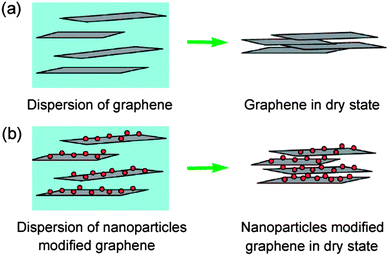 | ||
| Fig. 7 Schematic of (a) graphene nanosheets and (b) nanoparticle-modified graphene nanosheets in its dispersion and dry state. Reprinted from ref. 63 with permission. | ||
For example, Fan et al.64 have reported graphene–carbon black composite by ultrasonication and in-situ reduction of graphene oxide, showing a specific capacitance of 175 F g−1 at 10 mV s−1 in 6 M KOH aqueous solution. In situ growth and layer-by-layer assembly have also been developed for the fabrication of graphene–CNT composites. In this regard, Wei et al.60 have reported a novel strategy to prepare 3D CNT–graphene sandwich (CGS) structures with CNT pillars grown in between the graphene layers by Co-catalyst CVD approach (Fig. 8). The supercapacitor based on CGS exhibits a specific capacitance of 385 F g−1, much higher than that of the counterpart. The significant improvement of the electrochemical performance of CGS is mainly attributed to the unique sandwich structure of graphene and CNTs. Here CNTs have two functions, which not only act as a structural buffer for the large volume expansion of Co(OH)2 nanoparticles during the charge–discharge process, but also avoid the aggregation of graphene, therefore ensuring the electrolyte ion's diffusion. Furthermore, the interconnection of CNTs and graphene constructs a 3D conductive network for the transport of electrons, hence reducing the internal resistance of the electrode.
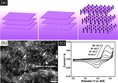 | ||
| Fig. 8 (a) Illustration of the formation of hybrid materials with CNTs grown in between graphene nanosheets, (b) SEM image and (c) CV curves at different scan rates of the resulting CNTs–graphene composite. Reprinted from ref. 60 with permission. | ||
In order to meet the need for high energy storage devices, metal oxides and conductive polymers have been extensively applied as the spacer to separate graphene nanosheets in view of their high capacitance. Among metal oxides, MnO2 is a promising candidate for supercapacitors due to its low cost, environmentally friendly nature, and special high capacity.66–69 More significantly, unlike other electrode materials, which should be used in strong acidic or alkaline electrolytes, MnO2 can be used in neutral aqueous electrolytes, and hence can meet the requirements for “green electrolyte” in supercapacitors. A MnO2 nanoneedle–graphene oxide composite has been synthesized by a simple soft chemical route in a water–isopropyl alcohol system, as shown in Fig. 9.65 The electrochemical performance of the nanocomposite was greatly enhanced. Wei et al.68 have developed a quick and easy method to synthesize graphene–MnO2 composites through the self-limiting deposition of nanoscale MnO2 on the surface of graphene under microwave irradiation. The graphene–MnO2 composite with 78 wt% MnO2 exhibits a specific capacitance as high as 310 F g−1 at 2 mV s−1 (even 228 F g−1 at 500 mV s−1), which is almost three times higher than that of pure graphene (104 F g−1) and birnessite-type MnO2 (103 F g−1). As for other transition metal oxides, Dai et al.62 have reported the in-situ growth of single crystalline Ni(OH)2 nanoplates on graphene nanosheets, displaying an extraordinarily high specific capacitance of 935 F g−1 within a potential range of 0.5 V. Li et al. realized the one-pot solvothermal synthesis of graphene–Fe3O4 composites.70 Similarly, graphene anchored with Co3O4 nanoparticles was prepared, showing an intriguing electrochemical performance.71
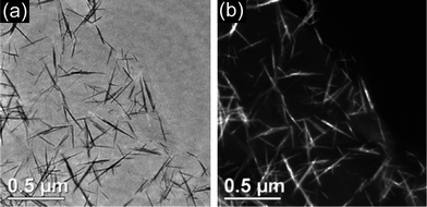 | ||
| Fig. 9 (a) Bright-field and (b) dark-field images of a MnO2 nanoneedle–graphene oxide composite. Reprinted from ref. 65 with permission. | ||
Conductive polymers (CPs), have been widely investigated for fabricating supercapacitors, especially for polyaniline (PANI), which has multiple redox states and good environmental stability. It can also be cheaply and easily fabricated into various nanostrucures. However, they usually suffer from degradation induced by the volume changes during the repeated charge–discharge process, leading to poor cycling performance.72–75 A rational construction of graphene–CPs composites nanostructure coupling their advantages will be an effective strategy to overcome this limitation. Shi et al.73 have prepared stable aqueous dispersions of chemically converted graphene–polyaniline nanofiber (CCG–PANI-NFs) composites. By subsequently filtrating the mixed dispersions, paper-like composite films have been produced, where PANI-NFs are uniformly sandwiched between CCG layers (Fig. 10(a and b)). The as-obtained composite film exhibits higher specific capacitance (210 F g−1) than that of the graphene (87 F g−1) and PANI-NFs (116 F g−1) films, respectively, implying a good synergistic effect between them. In another work, Wei et al.74 developed a facile approach to prepare PANI nanowire arrays vertically aligned on graphene oxide nanosheets, as shown in Fig. 10(c and d). The hierarchical nanocomposite, when applied as supercapacitor electrode materials, possessed higher electrochemical capacitance (555 F g−1) than randomly connected PANI nanowires obtained in the same condition (298 F g−1) with good cycling stability (92% capacity retention after 2000 cycles).
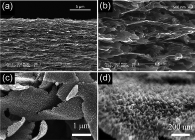 | ||
| Fig. 10 (a) Low- and (b) high-magnification cross-section SEM images of PANI-NF–graphene composite film, reprinted from ref. 73 with permission. (c) and (d) SEM images of PANI vertically aligned on graphene oxide nanosheets, reprinted from ref. 74 with permission. | ||
Based on the above discussion, the use of pseudo-capacitive materials as the spacer of graphene can effectively separate graphene nanosheets, avoiding their aggregation with high specific surface area. Accordingly, the presence of graphene greatly enhances the conductivity and mechanical resilience of pseudo-capacitive materials. The construction between them will also create amounts of pores, which not only increase the effective contact of active materials and electrolytes, but also maintain structural stability. In a nutshell, the composites constructed from graphene and pseudo-capacitive materials are one of the most promising electrodes for supercapacitors.
3.3. Ternary graphene-based nanocomposites
Until now, many materials have been developed as the electrode materials for supercapacitors. Each type of them has its pros and cons. Recently, much research on supercapacitors has been focused on designing and synthesizing hierarchical ternary composite electrode materials to fully exploit their advantages and overcome their disadvantages.76–78 Typically, Alshareef et al.76 have developed a three-component, flexible electrode using γ-MnO2 nanoflowers anchored onto CNTs as spacers for graphene nanosheets. Fig. 11(a) shows a schematic of the GN–(γ-MnO2–CNT) nanocomposite prepared by the ultrasonication of chemically functionalized GNs and γ-MnO2–CNTs. The corresponding SEM and TEM images have been shown in Fig. 11(b and c). The three-component composite electrode delivered the highest ever-reported specific capacitance of 308 F g−1 for symmetric supercapacitors containing MnO2 and GNs using a two-electrode configuration at 20 mV s−1. The as-fabricated supercapacitors also possess excellent cycling stability by retaining ∼90% of the initial specific capacitance after 5000 cycles. It can also be observed in Fig. 11(d) that the GN–(γ-MnO2–CNT) nanocomposite has much higher specific capacitance than that of the GN or γ-MnO2–CNT at the same scan rate, indicating the synergistic effects among them. Furthermore, Zhang et al.78 have reported the hierarchical graphene–polypyrrole–CNT ternary composites by an in situ polymerization method, exhibiting a specific capacitance of 362 F g−1 at 0.2 A g−1, under a two-electrode configuration. However, it remains a great challenge to rationally design and synthesize novel ternary or multinary composites for high energy and power density supercapacitors with long cycle life.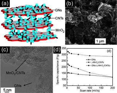 | ||
| Fig. 11 (a) Schematic, (b) SEM image, and (c) TEM image of the GNs–(MnO2–CNT) nanocomposite. (d) Specific capacitance change as a function of the scan rate of GNs, MnO2–CNTs, and GNs–(MnO2–CNT). Reprinted from ref. 76 with permission. | ||
4. 3D porous carbon based nanostructures
4.1. Templated mesoporous carbons (TMC)
The templated method is a powerful approach to create porous carbon materials with a tunable pore size, large specific surface areas and interconnected pore network, making them promising candidates for supercapacitor electrode materials.24,79–81 In disordered porous carbon, high resistance will be formed as a result of the tortuous diffusion path for the ions, especially at high current density. Since Ryoo et al.82–84 first reported the fabrication of ordered mesoporous carbons (OMCs) by a hard-template nanocasting strategy, numerous efforts have been devoted to the synthesis and electrochemical applications due to their uniform pore diameter and high pore volume. Hyeon et al.85 first reported that the OMCs possess excellent electrochemical performance compared with commercial carbon. Xing et al.86 have reported superior EDLCs performances of OMC by optimizing the ordered pore symmetries and mesopore structure. It is worth mentioning that Gogotsi et al.87 have suggested that a pore size distribution in the range of 2–5 nm, which is larger than the size of two solvated ions, is best for the improvement of energy and power densities. Despite all efforts, only moderate improvement has been achieved.Recently, OMCs incorporated with pseudo-active materials have been developed to further enhance their energy density. Xia et al.88 have realized the synthesis of PANI filled CMK-3 composite with a high specific capacitance of 900 F g−1, but its specific surface area decreased tremendously from 1300 to 35 m2 g−1. Li et al.89 have developed a facile strategy to synthesize a novel nanocomposite with PANI grown vertically on the outer surface of CMK-3. The overall synthetic procedure of PANI-NWs–CMK-3 composite was illustrated in Fig. 12(a). The composite with 40 wt% PANI (Fig. 12(b)), when applied as electrode, exhibited a large specific capacitance (470 F g−1), high rate capability (∼87% capacity retention as current densities increase from 0.1 to 2 A g−1), and good cycling stability (∼90.4% retention after 1000 cycles). Instead of PANI, polypyrrole (PPy) grown on OMC has also been realized by Park et al.90
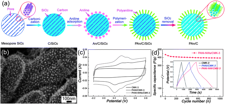 | ||
| Fig. 12 (a) Schematic illustration of the preparation route and (b) SEM images of PANI-NWs–CMK-3 nanocomposites; (c) CV curves of CMK-3, PANI-NPs–CMK-3 and PANI-NWs–CMK-3 at 20 mV s−1; (d) cycling stability of PANI-NWs–CMK-3, inset showing the charge–discharge curves of CMK-3, PANI-NPs–CMK-3 and PANI-NWs–CMK-3 at 0.1 A g−1. Reprinted from ref. 89 with permission. | ||
In the construction of a metal oxide–carbon hybrid structure, Shi et al.91 have reported MnO2–mesoporous carbon composite, synthesized by embedding MnO2 nanoparticles into the mesoporous carbon walls through the redox reaction between permanganate ions and carbons, as shown in Fig. 13(a). The synthesis of metal oxide nanoparticles within carbon mesopores shows a confined growth process that can facilitate controllable growth of the nanoparticles with optimal dimensions. A large specific capacitance of over 200 F g−1 for the MnO2–mesoporous carbon composite and 600 F g−1 for the MnO2 (Fig. 13(b)) were achieved with high electrochemical stability and high reversibility. The enhanced performance was attributed to the well-defined geometry and pore size of the ordered mesoporous nanocomposites, which facilitated the rapid ion transport via the high surface area. Similar results have also been reported by Ichihara et al.92 using a sonochemical method. Very recently, Li et al.93 have designed and synthesized the PANI–CMK-3–MnO2 ternary nanocomposites, where a layer of PANI uniformly deposited on the surface of CMK-3 incorporated MnO2 nanoparticles. In this regard, the incorporation of MnO2 nanoparticles not only contributes to a high capacity, but also stabilizes the interaction between the quinoid ring of PANI and the CMK-3–MnO2. On the other hand, the PANI nanolayer effectively avoids the dissolution of MnO2 nanoparticles during the charge–discharge process. The PANI–CMK-3–MnO2 ternary nanocomposites demonstrated an enhanced specific capacitance of 695 F g−1 with high cycling stability (88% capacity retention after 1000 cycles).
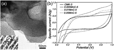 | ||
| Fig. 13 (a) Novel MnO2–mesoporous carbon composite with MnO2 embedded into the mesoporous carbon walls, and (b) CV curves of the composites with different MnO2 content in 2 M KCl at 5 mV s−1. Reprinted from ref. 91 with permission. | ||
4.2. Hierarchical porous carbon (HPC)
It is well-accepted that high energy and power densities are difficult to be simultaneously achieved through fine-tuned mesoporous carbons. Several studies suggested that micropores are essential for high energy storage, whereas mesopores (usually 2–8 nm) can accelerate the kinetic process of ion diffusion in the electrodes, improving the power density.94–96 Yamada et al.97 have reported the synthesis of ordered porous carbons consisting of meso/macro/micropores with large surface areas by a colloidal-crystal templating technique. A high specific capacitance of 200–350 F g−1 was achieved in an acidic electrolyte solution depending on the pore structures. The investigation on pore-dependent capacitance properties has revealed that the micropores adjacent to the open mouths of pores are effective in charge storage, and larger pores that are interconnected are important for smooth electrolyte transportation. Meanwhile, Song et al.98 and Lee et al.99 also predicted theoretically that hierarchical pore structure may lead to better electrochemical performances. Recently, Cheng et al.95,96 have synthesized 3D aperiodic hierarchical porous graphitic carbon (HPGC) as a potential electrode material for high power electrochemical capacitor applications, as shown in Fig. 14(a–d). The results have shown higher energy densities at high charge–discharge rates than that of the high surface area carbons previously reported (Fig. 14(d)). This type of 3D hierarchical carbon is characterized by four obvious advantages at different dimensions: macroporous cores (between 1 and 2 μm, serving as ion-buffering reservoirs), mesoporous walls (with thickness of 100–200 nm, ensuring smaller ion-transport resistance), micropores (with sizes about 0.7–1 nm, accommodating charges) and a localized graphitic structure (enhancing the electrical conductivity). Fig. 14(c) shows a schematic representation of the 3D structure.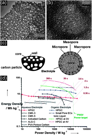 | ||
| Fig. 14 (a) SEM and (b) TEM images of HPGC, (c) schematic representation of the 3D hierarchical porous texture and (d) Ragone plot showing the position of HPGC material relative to other forms of carbon materials. Reprinted from ref. 95 with permission. | ||
This new HPGC nanostructure is expected to combine with pseudo-active materials as novel nanocomposite materials for the demands of high energy supercapacitors. Fig. 15 illustrates the potential hierarchical porous structure of HPGC incorporated with pseudo-active materials composite. However, it is worth pointing out that regardless of the type of carbon matrix, there still exists a compromise among the composition of individual components, and an optimized mass ratio of ingredients, for every composite material.
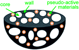 | ||
| Fig. 15 3D hierarchical porous structure of HPGC incorporated pseudo-active material composites. | ||
More complex hierarchical 3D porous carbon based composites have been proposed and proved to be promising electrode materials for supercapacitors.100 Rojo et al.101 have fabricated ultralightweight and highly conductive monolithic carbon aerogels with a 3D continuous micro- and macroporous structure through a PPO–PEO–PPO block copolymer assisted route. The resulting carbon monoliths exhibit remarkable values of capacitance of up to 225 F g−1 and 31 μF cm−2 with specific BET surface and micropore areas of 725 and 470 m2 g−1, respectively. To achieve best electrochemical performance, Lee et al. tend to propose ideal 3D composites, which are composed of well ordered 3D interconnected pores and a well ordered 3D interconnected electroactive nanomaterial with a conformal conductive coating layer.102 It is essential to add that the conducting coating should be porous for full contact between the core and electrolyte, as well as realizing high mechanical flexibility and resilience in order to accommodate for the volume changes of electrode materials.
5. Summary and outlook
In this review, we have summarized the recent progress of using 3D carbon-based nanostructures as electrode materials for advanced supercapacitor devices, mainly including CNTs-based networks, graphene-based architectures, hierarchical porous carbon-based nanostructures and even more complex carbon-based 3D configurations. Due to the structural interconnectivities, 3D carbon-based nanostructures not only create hierarchical porous channels, but also possess higher electrical conductivity and better structural mechanical stability. The rational combination of interconnected meso- and micropores in electrode materials will greatly improved their electrochemical performances, where micropores are essential for high energy storage and mesopores can accelerate the kinetic process of ion diffusion, respectively. The ability to tailor pore sizes in mesopore regime with a tailored micropore size is the key for optimized performance, which has been an interesting research topic so far.In view of the pure physical charge storage mechanism of carbon materials, the capacitance (or energy density) is still unsatisfactory whereas the pseudo-capacitive materials, such as metal oxides and conductive polymers, possess high specific capacitance. Therefore, higher energy storage could be achieved by combining EDL capacitance together with fast and highly reversible pseudo-capacitance utilizing their synergistic effects. On the other hand, a key limitation of metal oxides is their poor conductivity while conductive polymers suffer from the swelling and shrinking of structure during the charge–discharge process, and thus there should be a compromise among the individual components in order to enhance the energy density of the composites without sacrifice of the power density and cycling stability. Thus far, although considerable progress has been made, complete understandings of the relationship between 3D carbon-based nanostructures and enhanced electrochemical performance are still in their primary stage. There is tremendous room available in the design and synthesis of novel 3D carbon-based nanostructures electrode materials for advanced supercapacitor in terms of high energy density, high power density and long cycling life.
Supercapacitors are reckoned to complement and even replace batteries to some extent in certain applications. In hybrid electric vehicles, it remains a challenge to accommodate supercapacitors and other components in the vehicle hood due to limited space. To mitigate this problem, thin and flexible supercapacitors have been a research hotspot recently considering that they can fit anywhere and can even be mounted on the inner surfaces of the vehicle body. 3D carbon-based electrode materials will further push forward the development of advanced supercapacitors. Besides, a new trend in the development of electrode materials is the exploitation of graphene-like pseudo-active materials composed of single- or several-atom layers. The construction of 3D configurations between such graphene-like pseudo-capacitive materials and graphene–CNTs with high electrical conductivity will endow them with an excellent electrochemical performance for advanced supercapacitors. The safe operation and “green chemistry” in supercapacitors should also be considered for practical applications.
Acknowledgements
The authors would like to dedicate this paper to the late Prof. Jan Ma for his dedication and expertise provided in this work. The work is supported by the National Natural Science Foundation of China (20925621, 21236003, 21136006, 21206043), the Special Projects for Nanotechnology of Shanghai (11nm0500800, 11nm0500200), the Fundamental Research Funds for the Central Universities and the NRF-CREATE of Singapore.Notes and references
- J. M. Tarascon and M. Armand, Nature, 2001, 414, 359–367 CrossRef CAS.
- M. Winter and R. J. Brodd, Chem. Rev., 2004, 104, 4245–4269 CrossRef CAS.
- P. Simon and Y. Gogotsi, Nat. Mater., 2008, 7, 845–854 CrossRef CAS.
- M. Pumera, Energy Environ. Sci., 2011, 4, 668–674 CAS.
- S. J. Guo and S. J. Dong, Chem. Soc. Rev., 2011, 40, 2644–2672 RSC.
- M. D. Stoller and R. S. Ruoff, Energy Environ. Sci., 2010, 3, 1294–1301 CAS.
- A. Ghosh and Y. H. Lee, ChemSusChem, 2012, 5, 480–499 CrossRef CAS.
- L. L. Zhang and X. S. Zhao, Chem. Soc. Rev., 2009, 38, 2520–2531 RSC.
- P. J. Hall, M. Mirzaeian, S. I. Fletcher, F. B. Sillars, A. J. R. Rennie, G. O. Shitta-Bey, G. Wilson, A. Cruden and R. Carter, Energy Environ. Sci., 2010, 3, 1238–1251 CAS.
- H. Jiang, L. P. Yang, C. Z. Li, C. Y. Yan, P. S. Lee and J. Ma, Energy Environ. Sci., 2011, 4, 1813–1819 CAS.
- P. Simon and Y. Gogotsi, Acc. Chem. Res., 2012 DOI:10.1021/ar200306b.
- J. Miller and A. F. Burke, Electrochem. Soc. Interface, 2008, 17, 53–57 CAS.
- B. E. Conway, Electrochemical Supercapacitors: Scientific Fundamentals and Technological Applications, Kluwer Academic/Plenum Publisher, New York, 1999 Search PubMed.
- A. G. Pandolfo and A. F. hollenkamp, J. Power Sources, 2006, 157, 11–27 CrossRef CAS.
- D. S. Su and R. Schlögl, ChemSusChem, 2010, 3, 136–168 CrossRef CAS.
- C. Z. Yuan, B. Gao, L. F. Shen, S. D. Yang, L. Hao, X. J. Lu, F. Zhang, L. J. Zhang and X. G. Zhang, Nanoscale, 2011, 3, 529–545 RSC.
- C. Portet, G. Yushin and Y. Gogotsi, Carbon, 2007, 45, 2511–2518 CrossRef CAS.
- G. Lota, K. Fic and E. Frackowiak, Energy Environ. Sci., 2011, 4, 1592–1605 CAS.
- A. K. Geim and K. S. Novoselov, Nat. Mater., 2007, 6, 183–191 CrossRef CAS.
- L. L. Zhang, R. Zhou and X. S. Zhao, J. Mater. Chem., 2010, 20, 5983–5992 RSC.
- H. Jiang, J. Ma and C. Z. Li, Adv. Mater., 2012, 24, 4197–4202 CrossRef CAS.
- Z. P. Chen, W. C. Ren, L. B. Gao, B. L. Lu, S. F. Pei and H. M. Cheng, Nat. Mater., 2011, 10, 424–428 CrossRef CAS.
- R. B. Rakhi, W. Chen, D. Cha and H. N. Alshareef, Adv. Mater., 2012, 2, 381–389 CAS.
- Y. P. Zhai, Y. Q. Dou, D. Y. Zhao, P. F. Fulvio, R. T. Mayes and S. Dai, Adv. Mater., 2011, 23, 4828–4850 CrossRef CAS.
- C. Niu, E. K. Sichel, R. Hoch, D. Moy and H. Tennent, Appl. Phys. Lett., 1997, 70, 1480–1482 CrossRef CAS.
- T. Hiraoka, A. Izadi-Najafabadi, T. Yamada, D. N. Futaba, S. Yasuda, O. Tanaike, H. Hatori, M. Yumura, S. Iijima and K. Hata, Adv. Mater., 2010, 20, 422–428 CAS.
- L. Zhao, L. Z. Fan, M. Q. Zhou, H. Guan, S. Y. Qiao, M. Antonietti and M. M. Titirici, Adv. Mater., 2010, 22, 5202–5206 CrossRef CAS.
- S. A. Curran, P. M. Ajayan, W. J. Blau, D. L. Carroll, J. N. Coleman, A. B. Dalton, A. P. Davey, A. Drury, B. McCarthy, S. Maier and A. Strevens, Adv. Mater., 1998, 10, 1091–1093 CrossRef CAS.
- Y. T. Kim, K. Tadai and T. Mitani, J. Mater. Chem., 2005, 15, 4914–4921 RSC.
- L. H. Su, X. G. Zhang, C. Z. Yuan and B. Gao, J. Electrochem. Soc., 2008, 155, A110–A114 CrossRef CAS.
- Z. J. Fan, M. M. Xie, X. Jin, J. Yan and T. Wei, J. Electrochem. Soc., 2011, 659, 191–195 CAS.
- J. Yan, T. Wei, Z. J. Fan, W. Z. Qian, M. L. Zhang, X. D. Shen and F. Wei, J. Power Sources, 2010, 195, 3041–3045 CrossRef CAS.
- B. Sofiane, E. Kara and Y. Gleb, Energy Environ. Sci., 2012, 5, 6872–6879 Search PubMed.
- E. Frackowiak, Phys. Chem. Chem. Phys., 2007, 9, 1774–1785 RSC.
- J. H. Park, J. M. Ko and O. O. Park, J. Electrochem. Soc., 2003, 150, A864–A867 CrossRef CAS.
- H. Y. Lee and J. B. Goodenough, J. Solid State Chem., 1999, 144, 220–223 CrossRef CAS.
- H. Zhang, G. Cao, Z. Wang, Y. Yang, Z. Shi and Z. Gu, Electrochem. Commun., 2008, 10, 1056–1059 CrossRef CAS.
- H. Zhang, G. Cao, Z. Wang, Y. Yang, Z. Shi and Z. Gu, Nano Lett., 2008, 8, 2664 CrossRef CAS.
- C. L. Liang, Z. J. Li and S. Dai, Angew. Chem., Int. Ed., 2008, 47, 3696–3717 CrossRef CAS.
- H. Jiang, T. Zhao, C. Z. Li and J. Ma, Chem. Commun., 2011, 47, 8590–8592 RSC.
- H. Jiang, T. Sun, C. Z. Li and J. Ma, RSC Adv., 2011, 1, 954–957 RSC.
- H. Jiang, C. Z. Li, T. Sun and J. Ma, Nanoscale, 2012, 4, 807–812 RSC.
- C. Lin, J. A. Ritter and B. N. Popov, J. Electrochem. Soc., 1998, 145, 4097–4103 CrossRef CAS.
- H. Jiang, T. Zhao, C. Y. Yan, J. Ma and C. Z. Li, Nanoscale, 2010, 2, 2195–2198 RSC.
- H. Jiang, J. Ma and C. Z. Li, Chem. Commun., 2012, 48, 4465–4467 RSC.
- X. J. Zhang, W. H. Shi, J. X. Zhu, D. J. Kharistal, W. Y. Zhao, B. S. Lalia, H. H. Hng and Q. Y. Yan, ACS Nano, 2011, 5, 2013–2019 CrossRef CAS.
- Z. Chen, V. Augustyn, X. L. Jia, Q. F. Xiao, B. Dunn and Y. F. Lu, ACS Nano, 2012, 6, 4319–4327 CrossRef CAS.
- Z. Chen, V. Augustyn, J. Wen, Y. W. Zhang, M. Q. Shen, B. Dunn and Y. F. Lu, Adv. Mater., 2011, 23, 791–795 CrossRef CAS.
- Z. Chen, Y. C. Qin, D. Weng, Q. F. Xiao, Y. T. Peng, X. L. Wang, H. X. Li, F. Wei and Y. F. Lu, Adv. Funct. Mater., 2009, 19, 3420–3426 CrossRef CAS.
- R. R. Nair, P. Blake, A. N. Grigorenko, K. S. novoselov, T. J. Booth, T. Stauber, N. M. P. Peres and A. K. Geim, Science, 2008, 320, 1308 CrossRef CAS.
- C. Lee, X. D. Wei, J. W. Kysar and J. Hone, Science, 2008, 321, 385–388 CrossRef CAS.
- A. A. Balandin, S. Ghosh, W. Z. Bao, I. Calizo, D. Teweldebrhan, F. Miao and C. N. Lau, Nano Lett., 2008, 8, 902–907 CrossRef CAS.
- J. L. Xia, F. Chen, J. H. Li and N. J. Tao, Nat. Nanotechnol., 2009, 4, 505–509 CrossRef CAS.
- Y. Sun, Q. Wu and G. Q. Shi, Energy Environ. Sci., 2011, 4, 1113–1132 CAS.
- B. Luo, S. M. Liu and L. J. Zhi, Small, 2012, 8, 630–646 CrossRef CAS.
- M. D. Stoller, S. J. Park, Y. W. Zhu, J. H. An and R. S. Ruoff, Nano Lett., 2008, 8, 3498–3502 CrossRef CAS.
- Y. W. Zhu, M. D. Stoller, W. W. Cai, A. Velamakanni, R. D. Piner, D. Chen and R. S. Ruoff, ACS Nano, 2010, 4, 1227–1233 CrossRef CAS.
- W. Lv, D. M. Tang, Y. B. He, C. H. You, Z. Q. Shi, X. C. Chen, C. M. Chen, P. X. Hou, C. Liu and Q. H. Yang, ACS Nano, 2009, 3, 3730–3736 CrossRef CAS.
- Y. Xu, K. Sheng, C. Li and G. Shi, ACS Nano, 2010, 4, 4324–4330 CrossRef CAS.
- Z. Fan, J. Yan, L. Zhi, Q. Zhang, T. Wei, J. Feng, M. Zhang, W. Qian and F. Wei, Adv. Mater., 2010, 22, 3723–3728 CrossRef CAS.
- S. R. C. Vivekchand, C. S. Rout, K. S. Subrahmanyam, A. Govindaraj and C. N. R. Rao, J. Chem. Sci., 2008, 120, 9–13 CrossRef CAS.
- H. L. Wang, H. S. Casalongue, Y. Y. Liang and H. J. Dai, J. Am. Chem. Soc., 2010, 132, 7472–7477 CrossRef CAS.
- Y. Si and E. T. Samulski, Chem. Mater., 2008, 20, 6792 CrossRef CAS.
- J. Yan, T. Wei, B. Shao, F. Q. Ma, Z. J. Fan, M. L. Zhang, C. Zheng, Y. C. Shang, W. Z. Qian and F. Wei, Carbon, 2010, 48, 1731–1737 CrossRef CAS.
- S. Chen, J. W. Zhu, X. D. Wu, Q. F. Han and X. Wang, ACS Nano, 2010, 4, 2822–2830 CrossRef CAS.
- H. Jiang, T. Sun, C. Z. Li and J. Ma, J. Mater. Chem., 2012, 22, 2751–2756 RSC.
- H. Jiang, T. Zhao, J. Ma, C. Y. Yan and C. Z. Li, Chem. Commun., 2011, 47, 1264–1266 RSC.
- J. Yan, Z. Fan, T. Wei, W. Qian, M. Zhang and F. Wei, Carbon, 2010, 48, 3825–3833 CrossRef CAS.
- H. Jiang, C. Z. Li, T. Sun and J. Ma, Chem. Commun., 2012, 48, 2606–2608 RSC.
- K. F. Zhou, Y. H. Zhu, X. L. Yang and C. Z. Li, New J. Chem., 2010, 34, 2950–2955 RSC.
- Z. S. Wu, W. C. Ren, L. Wen, L. B. Gao, J. P. Zhao, Z. P. Chen, G. M. Zhou, F. Li and H. M. Cheng, ACS Nano, 2010, 4, 3187–3194 CrossRef CAS.
- Y. Huang, J. J. Liang and Y. S. Chen, Small, 2012, 8, 1805–1834 CrossRef CAS.
- Q. Wu, Y. X. Xu, Z. Y. Yao, A. R. Liu and G. Q. Shi, ACS Nano, 2010, 4, 1963–1970 CrossRef CAS.
- J. J. Xu, K. Wang, S. Z. Zu, B. H. Han and Z. X. Wei, ACS Nano, 2010, 4, 5019–5026 CrossRef CAS.
- A. Sumboja, X. Wang, J. Yan and P. S. Lee, Electrochim. Acta, 2012, 65, 190–195 CrossRef CAS.
- R. B. Rakhi, W. Chen, D. Cha and H. N. Alshareef, Adv. Energy Mater., 2012, 2, 381–389 CrossRef CAS.
- X. F. Xia, Q. L. Hao, W. Lei, W. J. Wang, H. L. Wang and X. Wang, J. Mater. Chem., 2012, 22, 8314–8320 RSC.
- X. J. Lu, F. Zhang, H. Dou, C. Z. Yan, S. D. Yang, L. Hao, L. F. Shen, L. J. Zhang and X. G. Zhang, Electrochim. Acta, 2012, 69, 160–166 CrossRef CAS.
- A. H. Lu and F. Schüth, Adv. Mater., 2006, 18, 1793–1805 CrossRef CAS.
- X. S. Zhao, F. Su, Q. Yan, W. Guo, X. Y. Bao, L. Lv and Z. Zhou, J. Mater. Chem., 2006, 16, 637–648 RSC.
- S. Yoon, J. Lee, T. hyeon and S. M. Oh, J. Electrochem. Soc., 2000, 147, 2507–2512 CrossRef CAS.
- R. Ryoo, S. H. Joo, M. Kruk and M. Jaroniec, Adv. Mater., 2001, 13, 677–681 CrossRef CAS.
- S. Jun, S. H. Joo, R. Ryoo, M. Kruk, M. Jaroniec, Z. Liu and T. Ohsuna, J. Am. Chem. Soc., 2000, 122, 10712–10713 CrossRef CAS.
- R. Ryoo, S. H. Joo and S. Jun, J. Phys. Chem. B, 1999, 103, 7743–7746 CrossRef CAS.
- J. Lee, S. Yoon, T. Hyeon, S. M. Oh and K. B. Kim, Chem. Commun., 1999, 2177–2178 RSC.
- W. Xing, S. Z. Qiao, R. G. Ding, F. Li, G. Q. Lu, Z. F. Yan and H. M. Cheng, Carbon, 2006, 44, 216–224 CrossRef CAS.
- J. Chmiola, G. Yushin, Y. Gogotsi, C. Portet, P. Simon and P. L. Taberna, Science, 2006, 313, 1760–1763 CrossRef CAS.
- Y. G. Wang, H. Q. Li and Y. Y. Xia, Adv. Mater., 2006, 18, 2619–2623 CrossRef CAS.
- Y. F. Yan, Q. L. Cheng, G. C. Wang and C. Z. Li, J. Power Sources, 2011, 196, 7835–7840 CrossRef CAS.
- Y. S. Choi, S. H. Joo, S. A. Lee, D. J. You, H. Kim, C. Park, H. Chang and D. Seung, Macromolecules, 2006, 39, 3275–3282 CrossRef CAS.
- X. P. Dong, W. H. Shen, J. L. Gu, L. M. Xiong, Y. F. Zhu, H. Li and J. L. Shi, J. Phys. Chem. B, 2006, 110, 6015–6019 CrossRef CAS.
- S. M. Zhu, H. S. Zhou, M. Hibino, I. Honma and M. Ichihara, Adv. Funct. Mater., 2005, 15, 381–386 CrossRef CAS.
- Y. F. Yan, Q. L. Cheng, V. Pavlinek, P. Saha and C. Z. Li, Electrochim. Acta, 2012, 71, 27–32 CrossRef CAS.
- J. Huang, B. G. Sumpter and V. Meunier, Chem.–Eur. J., 2008, 14, 6614–6626 CrossRef CAS.
- D. W. Wang, F. Li, M. Liu, G. Q. Lu and H. M. Cheng, Angew. Chem., Int. Ed., 2008, 47, 373–376 CrossRef CAS.
- D. W. Wang, F. Li, M. Liu, G. Q. Lu and H. M. Cheng, Angew. Chem., Int. Ed., 2009, 48, 1525 CrossRef CAS.
- H. Yamada, H. Nakamura, F. Nakahara, I. Moriguchi and T. Kudo, J. Phys. Chem. C, 2007, 111, 227–233 CAS.
- H. K. Song, Y. H. Jung, K. H. Lee and L. H. Dao, Electrochim. Acta, 1999, 44, 3513–3519 CrossRef CAS.
- G. J. Lee and S. I. Pyun, Langmuir, 2006, 22, 10659–10665 CrossRef CAS.
- P. J. Hall, M. Mirzaeian, S. I. Fletcher, F. B. Sillars, A. J. R. Rennie, G. O. Shitta-Bey, G. Wilson, A. Cruden and R. Carter, Energy Environ. Sci., 2010, 3, 1238–1251 CAS.
- M. C. Gutierrez, F. Pico, F. Rubio, J. M. Amarilla, F. J. Palomares, M. L. Ferrer, F. del Monte and J. M. Rojo, J. Mater. Chem., 2009, 19, 1236–1240 RSC.
- R. Liu, J. Duay and S. B. Lee, Chem. Commun., 2011, 47, 1384–1404 RSC.
| This journal is © The Royal Society of Chemistry 2013 |
