Nickel catalysts supported on calcium titanate for enhanced CO methanation
Chunmiao
Jia
ab,
Jiajian
Gao
a,
Jing
Li
a,
Fangna
Gu
*a,
Guangwen
Xu
a,
Ziyi
Zhong
c and
Fabing
Su
*a
aState Key Laboratory of Multiphase Complex Systems, Institute of Process Engineering, Chinese Academy of Sciences, Beijing, China 100190. E-mail: fngu@mail.ipe.ac.cn; fbsu@mail.ipe.ac.cn; Fax: +86-10-82544851; Tel: +86-10-82544850
bGraduate University of Chinese Academy of Sciences, Beijing, China 100049
cInstitute of Chemical Engineering and Sciences, A*star, 1 Pesek Road, Jurong Island, Singapore 627833
First published on 26th September 2012
Abstract
Nickel catalysts supported on the perovskite oxide CaTiO3 (CTO) were prepared by an impregnation method for CO methanation to produce synthetic natural gas (SNG). X-Ray diffraction, nitrogen adsorption, scanning electron microscopy, transmission electron microscopy, thermogravimetric analysis, H2-temperature programmed reduction and desorption, and X-Ray photoelectron spectroscopy were employed for the characterization of samples. The results revealed that the Ni/CTO catalysts showed a better performance than Ni/Al2O3 for CO methanation at various reaction conditions. The life time test at 600 °C and 3.0 MPa indicates that Ni/CTO is also more active, thermally stable and resistant to carbon deposition. This is because of the relatively weak Ni–CTO support interaction, highly stable CTO support, the absence of acidic sites on the surface of CTO and the proper Ni particle size of about 20–30 nm. The work is important for the development of effective methanation catalysts for SNG production.
1. Introduction
Recently, methanation of carbon oxides (CO and/or CO2) to produce synthetic natural gas (SNG) has drawn intensive attention due to the increasing demand for natural gas and the objective of reducing the emission of greenhouse gases into the atmosphere.1 The basic reactions in the methanation process are highly exothermic and are shown as follows: (1) CO + 3H2 → CH4 + H2O, ΔH298K = −206.1 kJ mol−1 and (2) CO2 + 4H2 → CH4 + 2H2O, ΔH298K = −165.0 kJ mol−1.2,3 Compared to noble metal catalysts, Ni-based catalysts are very attractive and promising due to their relatively high activity, low cost and good availability. Different materials, including Al2O3, SiC,4 SiO25 or CeO2,6 have been used to support Ni particles, and among which, Al2O3 is the most widely used to produce a methanation catalyst.7 The major drawbacks of Ni/Al2O3 catalysts, as pointed out previously by some researchers, include the sintering of Al2O3 and the formation of coke on Ni during the methanation process.8,9 To overcome these limits, great efforts have been made to modify the Ni/Al2O3 catalysts, e.g., through modification of the Al2O3 support and the use of various synthesis methods together with multiple promoters.10–14 Very recently, a Ni/Al2O3 catalyst with high Ni loadings (40 and 50 wt%), prepared by the solution combustion method, was found to be stable during a 50 h test, while a catalyst with lower Ni loadings of 10–30 wt% deactivated gradually.15 The factors leading to the deactivation of the Ni/Al2O3 catalyst include the sintering of the Al2O3 support and the generation of the NiAl2O4 spinel as well as severe coke formation.16,17 In other words, although the above catalysts are promising for industrial production, their thermal stability and resistance to carbon deposition still present a challenge.It is known that perovskite oxides possess some interesting physical and chemical properties, e.g., high thermal stability, good reactivity of lattice oxygen, low cost and rich resources. As catalysts or supports, perovskite oxides have been widely used in a number of high temperature reactions,18 such as steam reforming of methane,19 CO2 methanation,20 selective CO oxidation reactions,21 partial oxidation of CH4.22 Urasaki et al.19 reported that in a steam reforming reaction of methane, the Ni/perovskite catalysts exhibited higher catalytic activities and superior coking resistances compared to the conventional Ni/α-Al2O3 catalyst. This is because the lattice oxygen in the perovskite-supported catalysts was able to inhibit the formation of carbon during the reaction process. Furthermore, Takehira and coworkers23 evaluated the perovskite oxides XTiO3 (X = Ca, Sr, Ba), which contain a small amount of Ni in the Ti sites, and these catalysts showed high catalytic activities with a high resistance to coking because of their unique structure and the high dispersion of Ni. It was also thought that it was the perovskite structure which consequently separated NiO and then Ni metal. However, perovskite oxide-supported Ni catalysts have not been explored for the CO methanation reaction.
In this paper, we used CaTiO3 (CTO), one of the perovskite oxides, to prepare Ni catalysts (Ni/CTO) with low NiO loadings for CO methanation for the production of SNG and found that Ni/CTO catalysts exhibit better catalytic activity, superior thermal stability and a greater resistance to coke formation compared with Ni/Al2O3 catalysts, suggesting that CTO would be a good alternative material to the conventional Al2O3 support. Our work is significant for the development of effective CO methanation catalysts for SNG production.
2. Experimental
2.1. Catalyst preparation
All the catalysts were prepared by the wet impregnation method. Commercial perovskite CTO (NanTong AoXin Machineryco., Ltd., Purity > 95%) was calcined at 400 °C for 4 h before use. 1.945 g of Ni(NO3)2·6H2O (analytical-grade, Sinopharm Chemical Reagent Co. Ltd.) was dissolved in 13 mL of deionized water and 4.50 g of the CTO support was added to form a slurry, which was kept at room temperature for 8 h under vigorous stirring. The slurry was then heated to 80 °C to evaporate the liquid, dried at 110 °C overnight and further calcined at 400 °C for 4 h in air. The collected catalyst was denoted as 10Ni/CTO with a NiO loading of 10 wt%. Accordingly, 5Ni/CTO was prepared by the same method using 0.973 g of Ni(NO3)2·6H2O, 4.75 g of CTO and 15 mL deionized water. For a comparison, commercial γ-Al2O3 (GongYiHuaYu alumina Co. Ltd., China; Purity > 95%) was also calcined at 400 °C in air for 4 h before use and the 5Ni/Al2O3 and 10Ni/Al2O3 catalysts were prepared by the same method.2.2. Characterization
The X-ray powder diffraction (XRD) pattern was recorded on a PANalytical X'Pert PRO MPD with Kα radiation of Cu (λ = 1.5418 Å) at 40 KV and 40 mA, and the Debye–Scherrer equation was used to calculate the crystal size. The specific surface area of the catalysts was measured on a Quantachrome surface area & pore size analyzer NOVA 3200e. Before the measurement, the sample was degassed at 200 °C for 3 h under vacuum. The specific surface area was determined according to the Brunauer–Emmett–Teller (BET) method in the relative pressure range of 0.05–0.2. The microscopic feature of the samples was observed by field emission scanning electron microscope (SEM) (JSM-6700F, JEOL, Tokyo, Japan) and transmission electron microscopy (TEM) (JEM-2010F, JEOL, Tokyo, Japan). Prior to the TEM observation, the catalyst was first reduced in a continuous-flow fixed bed at 600 °C for 4 h under H2, with a flow rate of 50 mL min−1. Thermogravimetric (TG) analysis was conducted on a Seiko Instruments EXSTAR TG/DTA 6300. 10 mg of the sample was used and heated under air (200 mL min−1) from room temperature up to 1000 °C (10 °C min−1). The surface chemical composition was analyzed by an X-Ray photoelectron spectroscopy (XPS) test conducted on a VG ESCALAB 250 spectrometer (Thermo Electron, U.K.) with a non-monochromatized Al–Kα X-Ray source (1486 eV). The deposited carbon content was measured using an CS-344 Infrared Analyzer (Leco, US). H2 temperature-programmed reduction (H2-TPR) and desorption (H2-TPD), and NH3 temperature-programmed desorption (NH3-TPD) were carried out on a Quantachrome Automated chemisorption analyzer (ChemBET pulsar TPR/TPD). The H2 consumption or NH3 desorption was detected continuously as a function of increasing temperature using a thermal conductivity detector (TCD). For the H2-TPR test, 0.1 g of the sample was loaded into a quartz U-tube and heated from room temperature to 400 °C at 10 °C min−1 and maintained for 1 h under Ar flow. The sample was then cooled to room temperature, followed by heating to 1000 °C at 10 °C min−1 under a 10.0 vol% H2/Ar atmosphere with a gas flow of 30 mL min−1. For the NH3-TPD test, 0.3 g of the sample was loaded into a quartz U-tube and reduced from room temperature to 600 °C, according to the H2-TPR procedure. The gas flow was then switched to a He flow (30 mL min−1) and the sample was cooled to 100 °C and saturated with ammonia (10.0 vol% NH3/He). After removing the physically adsorbed ammonia in a He flow for 1 h, the sample was heated to 600 °C at 10 °C min−1 under a continuous He atmosphere. For the H2-TPD test, 0.3 g of the catalyst was loaded into a quartz U-tube and first reduced at 600 °C for 4 h under a 10.0 vol% H2/Ar atmosphere, with a gas flow of 30 mL min−1, and then cooled to room temperature and maintained for 2 h. After removing the physically adsorbed hydrogen by flushing with Ar for 2 h at the flow rate of 30 mL min−1, the sample was heated to 600 °C with a ramp of 10 °C min−1 in an Ar flow. The number of surface Ni sites per unit mass of catalyst was determined by means of H2-TPD with an adsorption stoichiometry of H![[thin space (1/6-em)]](https://www.rsc.org/images/entities/char_2009.gif) :Ni = 1:1. The peak area of the H2-TPD profile was normalized by that of H2-TPR of a standard CuO sample. The turnover frequency (TOF) value was calculated based on the formula as followed:
:Ni = 1:1. The peak area of the H2-TPD profile was normalized by that of H2-TPR of a standard CuO sample. The turnover frequency (TOF) value was calculated based on the formula as followed:where VCO,in and VCO,out are the volume flow rates of CO at the inlet and outlet of the reactor at standard temperature and pressure (STP), mL s−1; RH2/Ni = 2 is the stoichiometric factor of the H2
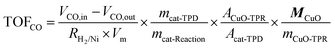 :Ni ratio in the chemisorption; Vm = 22414 mL mol−1 is the molar volume of CO gas at STP; mcat-TPD is the mass of the catalysts used in the H2-TPD experiment, g; mcat-Reaction is the mass of the catalysts used in the CO methanation reaction, g; ACuO-TPR is the peak area of the H2-TPR curve of standard CuO; Acat-TPD is the peak area of the H2-TPD curve of the catalyst; MCuO = 79.54 g mol−1 is the mole mass of CuO; mCuO-TPR is the mass of the CuO used in the H2-TPR experiment, g.
2.3. Catalytic measurement
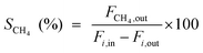
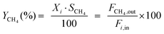
The catalytic tests for CO and CO2 methanation were carried out in a fixed-bed reactor equipped with a quartz tube and stainless steel tube (both with a diameter of 8 mm) respectively. A thermocouple was inserted into the furnace chamber and bonded to the outside of the reactor tube in the middle of the catalyst bed to control the reaction temperature. The CO methanation was tested under 0.1 and 3.0 MPa from 300 to 600 °C, and CO2 methanation was performed under 0.1 MPa. 0.6 g of the catalyst (20–40 mesh), diluted with 3.0 g of quartz sand of the same mesh, was placed in the tube reactor. The catalyst was first reduced at 600 °C for 4 h under a pure H2 flow (100 mL min−1). The gas flow was then switched to a feed gas with a molar ratio of H2:CO:N2 = 3:1:1 and the total flow rate was set to 100 mL min−1, determined by mass flow controllers corresponding to a weight hourly space velocity (WHSV) of 10000 mL g−1 h−1. On heating the mixture from 300 to 600 °C with an interval of 50 °C, the catalytic activities of the catalysts were measured under 0.1 and 3.0 MPa, respectively. A life time test was performed at 600 °C and 3.0 MPa. For the hydrothermal treatment, 0.5 g of the unreduced catalyst was loaded into a quartz tube and subjected to an atmosphere of steam and hydrogen, with a volume ratio of 10:1, at 800 °C for 5 hours under 0.1 MPa, and then the catalyst was cooled to room temperature in pure H2. For the CO2 methanation, a feed gas with a molar ratio of H2:CO2:N2 = 4:1:1 was used. The inlet and outlet gas, after cooling with a cold trap, were analyzed online by Micro GC (3000 A; Agilent Technologies). After one hour of steady-state operation at each temperature, the concentrations of the H2, N2, CH4, CO and CO2 contents in the gas products were analyzed by a thermal conductivity detector (TCD) with a Molecular Sieve column using N2 as an internal standard. The CO and CO2 conversion, CH4 selectivity and yield are defined as follows: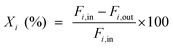 | (1) |
 | (2) |
 | (3) |
Here, i represents CO or CO2, X is the conversion of CO or CO2, S is the selectivity of CH4, Y is the CH4 yield, Fx,in and Fx,out are the molar flow rates of species x (x = CH4, CO, or CO2) at the inlet and outlet respectively.
3. Results and discussion
3.1. Catalyst characterization
Table 1 compiles the surface areas and pore volumes of the supports and catalysts. CTO has a very low surface area (1.6 m2 g−1) and is almost non-porous. After NiO loading, the surface area of the CTO supported catalysts increase slightly. This can be attributed to the loading of small NiO nanoparticles onto the surface of CTO, which can be seen from the SEM images below. However, for the Al2O3 and Ni/Al2O3 catalysts, their surface areas (246–305 m2 g−1) and total pore volumes (0.34–0.44 m3 g−1) are much larger than those of the CTO and Ni/CTO catalysts but become smaller after the NiO loading, mainly because the density of the NiO particles is larger than that of the porous Al2O3 and some of the pores may be blocked by the NiO nanoparticles.| Catalyst sample | BET surface area (m2 g−1) | Total pore volume (m3 g−1) | Mean particle size (nm) | ||
|---|---|---|---|---|---|
| NiOa | Nib | Nic | |||
| a Calculated by the XRD diffraction peak (2θ = 43.5°) using the Debye–Scherrer equation. b Calculated by the XRD diffraction peak (2θ = 44.6°) using the Debye–Scherrer equation. c Determined according to the TEM images. | |||||
| CTO | 1.6 | — | — | — | — |
| 5Ni/CTO | 2.9 | — | 19 | 16 | 10–20 |
| 10Ni/CTO | 3.2 | — | 24 | 23 | 20–30 |
| Al2O3 | 305.2 | 0.44 | — | — | — |
| 5Ni/Al2O3 | 268.5 | 0.37 | — | — | 3–5 |
| 10Ni/Al2O3 | 246.3 | 0.34 | — | — | 6–10 |
Fig. 1 presents the XRD patterns and TG curves of the calcined catalysts and the support. For the Ni/CTO samples in Fig. 1a, the diffraction peaks at 33.3, 47.9, 59.6, and 70.0° are a typical feature of CTO.23,24 From the enlarged view in Fig. 1b, the peaks at 37.4, 43.5, and 63.2° can be attributed to (111), (200), and (220) of NiO (JCPDS 00-001-1239).25 As expected, with the increase in the NiO loading from 5 to 10 wt%, the intensities of these peaks are also obviously increased, indicating the formation of larger NiO particles. The sizes of the NiO particles on 5Ni/CTO and 10Ni/CTO are calculated to be 19 and 24 nm, respectively (see Table 1). The XRD patterns of the Al2O3 support and Ni/Al2O3 catalysts are depicted in Fig. 1c, in which an extremely weak diffraction peak at 43.3°, contributed to NiO, is detected, indicating the low NiO loading or high dispersion.26Fig. 1d shows the TG/DTA curves of the two supports. Clearly, CTO experiences a weight loss of less than 0.5 wt% at 1000 °C, much lower than that of Al2O3 (∼5 wt%), suggesting the superior thermal stability of CTO to Al2O3.27,28
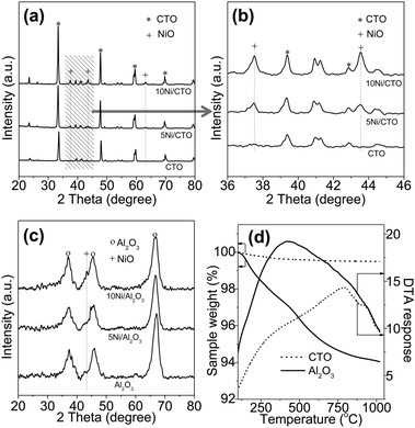 | ||
| Fig. 1 XRD patterns of CTO and the Ni/CTO catalyst (a), enlarged view (b), Al2O3 and catalysts Ni/Al2O3 (c), and TG/DTA curves of the CTO and Al2O3 supports (d). | ||
Fig. 2 shows the H2-TPR, H2-TPD, and NH3-TPD curves of the supports and Ni catalysts. From Fig. 2a, it can be seen that there is no obvious reduction peak for both the CTO and Al2O3 supports, implying that they are non-reducible under this condition. The reducible NiO peaks of the catalysts can be approximately classified into three types: an α-type (weak interaction of the NiO and support, 290–475 °C), a β-type (mid-interaction, 475–753 °C), and a γ-type (strong interaction, 753–894 °C).9,15,29 The H2 consumption curves of the Ni catalysts are fitted by Gaussian-type functions and the quantitative results are listed in Table 2. Accordingly, we can see that the reducible NiO peak in the 10Ni/CTO samples is located in the range of 295–471 °C, which all belong to the reduction of α-type NiO i.e. free Ni which interacts weakly with the CTO support, and the 5Ni/CTO catalyst possesses the same NiO type (reducible peak from 311 to 471 °C). In contrast, for the Ni/Al2O3 catalysts, both the reducible peaks include three sub-peaks corresponding to the α-type, β-type, and γ-type. In particular, the β-type NiO becomes dominant and the fraction increases with the NiO loading (42.4% for 5Ni/Al2O3 to 53.5% for 10Ni/Al2O3 in Table 2). The γ-type NiO is also found in both catalysts, implying NiO strongly interacts with Al2O3 and partly generates the NiAl2O4 spinel structure, which is highly stable and hence difficult to be reduced.25 In short, the metal–support interaction in Ni/CTO is relatively weaker than that of Ni/Al2O3. The surface acidic properties of the supports and catalysts are examined by NH3-TPD, as shown in Fig. 2b. There is no desorption peak of ammonia on both CTO and 10Ni/CTO in the temperature range of 100–600 °C, indicating the lack of acidic sites on their surface. In contrast, a broad desorption peak is observed over Al2O3 and 10Ni/Al2O3 in the range of 150–450 °C, which can be attributed to desorbed NH3 from the acid sites.30,31 In short, the surface of 10Ni/CTO is non-acidic in nature while that of 10Ni/Al2O3 shows relatively strong acidic properties. Fig. 2c shows the H2-TPD curves of the reduced catalysts. We can see that the TPD profiles show H2 desorption peaks in the range of 50–360 °C for both catalysts, and the H2 adsorption amount for the 10Ni/Al2O3 catalyst is 14.6 μmol gcat−1, much higher than that of the 10Ni/CTO catalyst (5.0 μmol gcat−1), possibly because the smaller Ni particles are well dispersed on the Al2O3 support due to its high surface area and intricate pore structure.
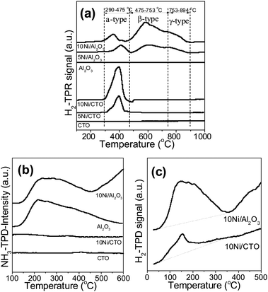 | ||
| Fig. 2 H2-TPR (a) and NH3-TPD curves (b) of the supports and Ni catalysts, and H2-TPD profile of the reduced Ni catalysts (c). | ||
| Catalysts | T m (°C) | Fraction of total area (%) | ||||
|---|---|---|---|---|---|---|
| α-type NiO | β-type NiO | γ-type NiO | α-type NiO | β-type NiO | γ-type NiO | |
| 5Ni/CTO | 391 | — | — | 100 | — | — |
| 10Ni/CTO | 384 | — | — | 100 | — | — |
| 5Ni/Al2O3 | 408 | 604 | 743 | 24.2 | 42.4 | 33.4 |
| 10Ni/Al2O3 | 351 | 588 | 739 | 12.0 | 53.5 | 34.4 |
Fig. 3 presents the SEM images of the supports and the unreduced catalysts. Fig. 3a shows that the CTO support possesses a smooth surface. For the 5Ni/CTO (Fig. 3c) and 10Ni/CTO (Fig. 3e) catalysts, it can be seen that the NiO particles are uniformly dispersed on the CTO surface. Furthermore, the NiO particle size in the 10Ni/CTO sample appears slightly larger than that in the 5Ni/CTO catalyst, in agreement with the XRD results (Fig. 1). In contrast, the Al2O3 support itself consists of small particles (Fig. 3b). After loading with NiO, no visible change can be seen in 5Ni/Al2O3 (Fig. 3d) and 10Ni/Al2O3 (Fig. 3f). All the SEM images indicate that the NiO particles are well dispersed on the surface of the CTO and Al2O3 supports.
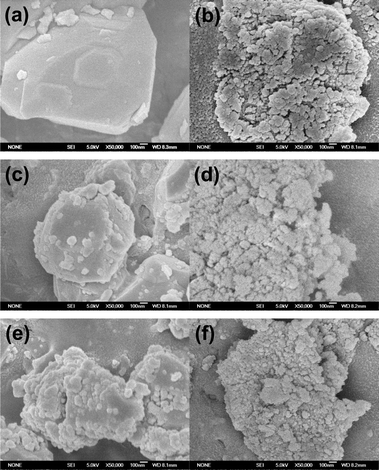 | ||
| Fig. 3 SEM images of the supports and the Ni catalysts before reduction: (a) CTO, (b) Al2O3, (c) 5Ni/CTO, (d) 5Ni/Al2O3, (e) 10Ni/CTO, and (f) 10Ni/Al2O3. | ||
Fig. 4 shows the TEM images of the reduced Ni catalysts. The Ni particles are well dispersed on the CTO support surface (5Ni/CTO in Fig. 4a and 10Ni/CTO in Fig. 4c). The Ni particle sizes in the 5Ni/CTO and 10Ni/CTO catalysts are about 10–20 nm and 20–30 nm, respectively. Fig. 4e shows that smaller Ni particles (5–10 nm) are dispersed on the Al2O3 support. In addition, Fig. 4b, d, and f show the HRTEM images of the Ni particles with an exposed Ni lattice space of 0.2 nm, corresponding to the Ni(111) space, which is the active face for methanation.11,32
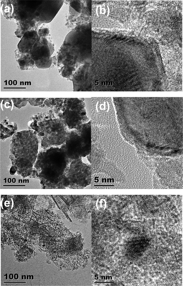 | ||
| Fig. 4 TEM images: (a and b) reduced 5Ni/CTO and Ni particles, (c and d) reduced 10Ni/CTO and Ni particles; (e and f) reduced 10Ni/Al2O3 and Ni particles. | ||
Fig. 5 displays the XPS spectra of the Ni 2p and O 1s orbitals and Table 3 lists the data for the other elements of the supports. The XPS spectra of all the samples confirm that the expected elements (Ni, Ca, Ti, Al and O) are present in Ni/CTO and Ni/Al2O3. The surface of the Ni/CTO catalysts are covered with a small portion of metal Ni (Ni 2p3/2 at around 853.0 eV) and a larger portion of Ni oxide (Ni 2p3/2 at around 856.4 eV), due to the partial surface oxidation of Ni during the sample transfer before the XPS test.33,34 Moreover, the Ni 2p3/2 peak from 10Ni/CTO shifts to a lower binding energy of 852.3 eV compared with that from 5Ni/CTO (856.4 eV), indicating that the interaction of the Ni particles with the CTO support becomes weaker as the loading amount of Ni increases. For the 10Ni/Al2O3 catalyst, two peaks at 856.4 and 874.0 eV, which are assigned to NiO 2p3/2 and NiO 2p1/2 respectively, are observed, although no obvious signal from metal Ni is identified.35 The absence of a reduced Ni phase in the 10Ni/Al2O3 catalyst is likely attributed to the oxidation of metallic Ni after exposure to air because the catalysts were not reduced again in situ during the XPS measurement. Additionally, the formation of a highly stable NiAl2O4 phase also accounts for this phenomenon.35 The O 1s signals in Fig. 5b for the Ni/CTO catalysts can be fitted to two peaks around 530.0 and 532.0 eV, respectively. With the increase of the NiO loading, the proportion of O in NiO (530.0 eV) increases compared with O in CTO (532.0 eV).36,37 10Ni/Al2O3 has a broader O 1s peak, which can be fitted with three sub-peaks corresponding to three types O on NiO (529.8 eV), Al2O3 (531.0 eV) as well as NiAl2O4 (532.0 eV) due to the strong interaction between Ni and support Al2O3, respectively.35,38,39 Apart from these, the binding energies of the other elements (Ca 2p3/2, Ca 2p1/2, Ti 2p3/2, Ti 2p1/2, and Al 2p) have no obvious chemical shift, implying that the chemical environment of both supports may not be changed after Ni loading.40
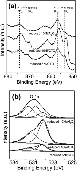 | ||
| Fig. 5 Ni 2p (a) and O 1s (b) XPS spectra of the 5Ni/CTO, 10Ni/CTO and 10Ni/Al2O3 catalysts after reduction. | ||
| Catalyst sample | Binding energy (eV) | ||||
|---|---|---|---|---|---|
| Ca | Ti | Al | |||
| Ca 2p3/2 | Ca 2p1/2 | Ti 2p3/2 | Ti 2p1/2 | Al 2p | |
| 5Ni/CTO | 346.7 | 350 | 458.8 | 464.6 | — |
| 10Ni/CTO | 346.4 | 350 | 458.6 | 464.3 | — |
| 10Ni/Al2O3 | — | — | — | — | 73.9 |
3.2. Catalyst activity
Fig. 6 shows the activities of the Ni catalysts for CO methanation at 0.1 MPa. Overall, the CO conversion and CH4 yield over the Ni/CTO catalysts present a volcano-shaped trend as the reaction temperature changes, in agreement with the thermodynamic calculation.3 The CO conversion in Fig. 6a almost reaches 100% over the 10Ni/CTO catalyst at 400 °C, while over the 5Ni/CTO catalyst it needs a higher reaction temperature of 450 °C to reach the same CO conversion. At the same time, the maximum CO conversion over 10Ni/Al2O3 is only 28% at 600 °C, and that over the 5Ni/Al2O3 catalyst is even lower (8%) at 500 °C. The maximum CH4 selectivity for the 10Ni/CTO and 5Ni/CTO catalysts is 85% at 400 °C and 80% at 450 °C in Fig. 6b, respectively. In addition, the maxima for the CH4 selectivity over 10Ni/Al2O3 and 5Ni/Al2O3 are around 80% and 88%, respectively. From Fig. 6c, the maximum CH4 yield for the 10Ni/CTO catalyst is 84% at 400 °C, and 80% for 5Ni/CTO at 450 °C. Meanwhile, the maximum CH4 yields for the 10Ni/Al2O3 and 5Ni/Al2O3 samples are just 24% and 6%, respectively. In order to further confirm the superiority of the 10Ni/CTO catalyst, the TOF values were calculated based on the H2-TPD and CO conversion results at 400 °C. The TOFCO value over 10Ni/CTO is 2.4 s−1, 24 times that of the 10Ni/Al2O3 catalyst (0.1 s−1), indicating the catalytic efficiency of reduced 10Ni/CTO is significantly higher than that of 10Ni/Al2O3. In addition, we tried to completely reduce both catalysts at 800 °C for 4 h in pure H2 and found that the CO conversion and CH4 yield over 10Ni/Al2O3 are still much lower than that for 10Ni/CTO at 0.1 MPa and 120000 mL g−1 h−1 (data not shown here). Therefore, we can deduce that 10Ni/CTO is more active than the 10Ni/Al2O3 catalyst.
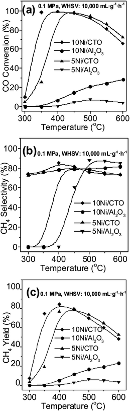 | ||
| Fig. 6 Catalytic activities of the Ni catalysts at 0.1 MPa: (a) CO conversion, (b) CH4 selectivity, and (c) CH4 yield. | ||
Previously, a great deal of effort has been expended to understand the interaction between the metal component and the support and a strong metal support interaction (SMSI) was often used to explain experimental phenomena.4,36,41,42 However, the above characterization results demonstrate that the Ni/CTO catalysts have weaker metal–support interactions compared with the Ni/Al2O3 catalysts but show better catalytic performances. Thus, the SMSI model is not appropriate to explain the above phenomena. Therefore, we suspect that the NiO particles strongly interact with the support and may not be fully available in the catalytic reaction as some of them are difficult to be reduced to act as an “active” role. This is what occurred in Ni/Al2O3, although it has a high dispersion of Ni nanoparticles. In order to fully reduce the NiO species in this catalyst, a higher reduction temperature is needed, which will adversely lead to the agglomeration of Ni particles and the support and the formation of NiAl2O4.35 These may not be helpful for improving the catalytic activity of Ni/Al2O3. Contrarily, for the Ni/CTO catalysts, all the NiO particles can be reduced, even at the low reduction temperature of 600 °C, which leads to a full utilization of the Ni species and minimum impact to the sintering of Ni and the support. We can thus conclude that a weak interaction in the Ni/CTO catalysts is responsible for its good catalytic performances.
Fig. 7 shows the catalytic properties of CO methanation under 3.0 MPa over the 10Ni/CTO and 10Ni/Al2O3 catalysts. As we know, this reaction is volume-reduced and normally conducted at high pressure (2.94–3.43 MPa) in industry.43 It can be seen that the CO conversion (Fig. 7a) over the 10Ni/CTO catalyst reaches almost 100% and remains constant from 350 to 600 °C. However, the CO conversion over the 10Ni/Al2O3 catalyst increases with heating and only reaches 73% at a temperature of 600 °C. It can be seen that the CH4 selectivity (Fig. 7b) on 10Ni/CTO remains between 80 to 90% during the whole temperature range, while the selectivity for 10Ni/Al2O3 reaches a maximum of 60% at 600 °C. In Fig. 7c, the maximum value for the CH4 yield on 10Ni/CTO is around 88% from 450 to 600 °C but is only 45% for the 10Ni/Al2O3 sample at 600 °C. In addition, the thermodynamic equilibrium data3 is included as a comparison. It can be seen that the CO conversion on the 10Ni/CTO catalyst almost reaches the thermodynamic equilibrium value above 600 °C and there is a large difference for 10Ni/Al2O3. For the CH4 selectivity and yield, a gap between the experimental and thermodynamic equilibrium can be seen, especially over 10Ni/Al2O3. Therefore, the results from the high pressure test still indicate that the 10Ni/CTO catalyst is more active than 10Ni/Al2O3.
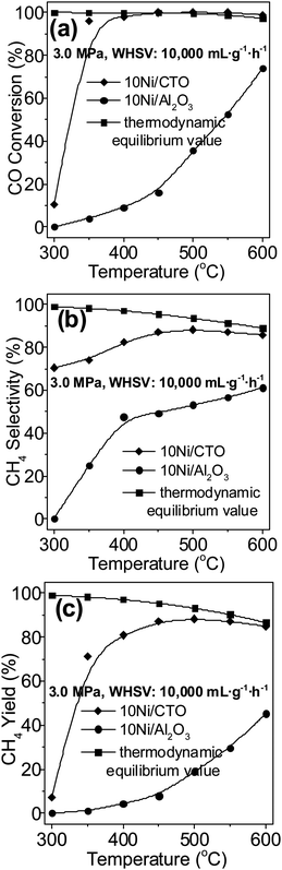 | ||
| Fig. 7 Catalytic activities of the Ni catalysts at 3.0 MPa: (a) CO conversion, (b) CH4 selectivity, and (c) CH4 yield. | ||
Fig. 8 shows the life time test results of 10Ni/CTO and 10Ni/Al2O3 at 600 °C and 3.0 MPa. For the 10Ni/CTO catalyst, the CO conversion (Fig. 8a), CH4 selectivity (Fig. 8b), and CH4 yield (Fig. 8c) is ∼100, ∼84, and ∼83%, respectively, and these remain constant during a 50 h run. In contrast, the activity of the 10Ni/Al2O3 catalyst has a remarkable decline after only 20 h. For instance, the CO conversion decreases from 70 to 45% and the CH4 yield drops from 41to 18%, suggesting a better long term performance for 10Ni/CTO.
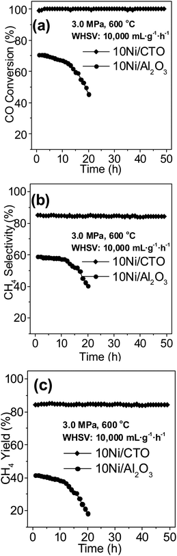 | ||
| Fig. 8 Catalytic performance of the Ni catalysts during a long test run at 600 °C and 3.0 MPa: (a) CO conversion, (b) CH4 selectivity, and (c) CH4 yield. | ||
Fig. 9a shows the XRD pattern of the used 10Ni/Al2O3 catalyst after a 20 h test and a freshly reduced catalyst for comparison. For the reduced catalyst, there are no metallic Ni peaks identified but after the long lifetime test, the Ni peaks located at 44.8, 51.9, and 76.6° appear and the Ni particle size is calculated to be about 26 nm, suggesting the sintering and agglomeration of the Ni particles after long term methanation.25 However, for the 10Ni/CTO catalyst in Fig. 9b, no obvious change is observed between the reduced and used catalyst after the 50 h reaction, indicating its good stability. Fig. 9c shows the SEM image of the 10Ni/Al2O3 catalyst after a 20 h test. It can be seen that there are some filamentous carbons formed, suggesting that carbon deposition occurred on the surface of 10Ni/Al2O3, consistent with previous results.26 In contrast, for the 10Ni/CTO catalyst in Fig. 9d, no such carbon filaments can be found even after a 50 h reaction. The amount of carbon deposited on the 10Ni/CTO catlyst surface after a 50 h test and on 10Ni/Al2O3 after a 20 h, analyzed by a CS-344 Infrared Analyzer, is 1.4 and 1.6 wt%, and the average carbon deposition rate is 0.03 and 0.08 wt% h−1, respectively, suggesting a much stronger resistance to carbon deposition for 10Ni/CTO. It has been pointed out that coking and sintering are the main factors for the deactivation of metal nanoparticles and the Ni-based catalysts are more susceptive to deposited carbon than other active components during the methanation process.1,9,44,45 In the CO methanation process, the carbon deposition mainly comes from the Boudouard reaction (2CO ↔ C + CO2), carbon monoxide reduction (CO + H2 ↔ C + H2O) and methane cracking (CH4 ↔ C + 2H2).8 According to the thermodynamic analysis,3 most of the carbon comes from the Boudouard reaction because its equilibrium constant (K) is much larger than that of the other reactions. It should be pointed out that, differing from the literature reported conditions, such as those used in the removal of CO46 and other gases with high H2 content,47,48 the feed gas (CO:H2:N2 = 3:1:1) used in our work is rich in carbon content and thus carbon deposition is much easier. It has been reported that carbon deposition is closely related to the surface chemistry of the active metal and the support, the dispersion and size of the active metal nanoparticles and the reaction conditions. The Al2O3 used here is highly porous and acidic and carbon is favorably deposited in the pores.31,49 The sintering of the Al2O3 support at high temperatures leads to the aggregation of Ni particles, which would exacerbate the carbon deposition.50 In contrast, CTO has less pores and basic surface properties, thus showing a higher resistance to carbon deposition. In addition, the migration of mobile oxygen from the perovskite support to the metallic Ni particles in Ni/CTO19,24,31,48 to reduce deposited carbon may be another reason.
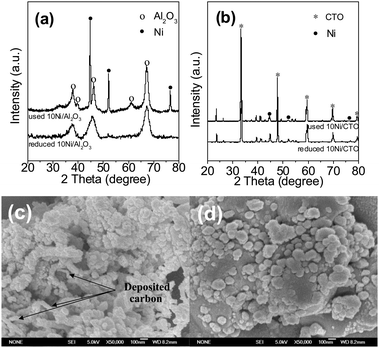 | ||
| Fig. 9 XRD patterns of the reduced and used 10Ni/Al2O3 (a) and 10Ni/CTO (b) catalysts, and SEM images of the used 10Ni/Al2O3 (c) and 10Ni/CTO (d) catalysts. | ||
The catalytic properties of 10Ni/CTO and 10Ni/Al2O3 after an HT treatment are shown in Fig. 10. It can be seen that the maximum CO conversion and CH4 yield over 10Ni/CTO-HT is around 65% (Fig. 10a) and 45% (Fig. 10b) at 550 °C, respectively, much higher than those of 10Ni/Al2O3-HT, although the activity of both catalysts declines compared with that of the fresh catalysts in Fig. 6. According to the XRD analysis on the catalysts after hydrothermal treatment (not shown here), a severe phase transformation of the Al2O3 support (partly from γ-type to η-type) occurs and the Ni peaks appear as a result of the aggregation of small Ni particles (size increased from about 5–10 nm to about 18 nm), while the structure of 10Ni/CTO is almost unchanged and the Ni particle size is slightly larger (from 23 to 30 nm). Hence, the better stability of 10Ni/CTO, especially for the CTO support, is confirmed, which guarantees the superior catalytic activity and stability of the Ni/CTO catalysts. In industrial methanation processes, steam is often added to the reaction system for the benefit of heat transmission and the diminishment of deposited carbon.51 Thus, the hydrothermal stability of the Ni catalysts is in high demand.52
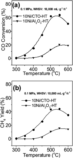 | ||
| Fig. 10 Catalytic activities of the Ni catalysts after hydrothermal treatment: (a) CO conversion and (b) CH4 yield. | ||
CO2 methanation, as another essential methanation process, was also carried out over the 10Ni/CTO and 10Ni/Al2O3 catalysts, as shown in Fig. 11. Apparently, the maximum CO2 conversion over 10Ni/CTO reaches 75% at 400 °C, as shown in Fig. 11a, while the maximum conversion over 10Ni/Al2O3 is only around 5%, and it finally reaches its maximum value of 84% at 600 °C. Fig. 11b shows that the CH4 yield over 10Ni/CTO substantially exceeds that over the 10Ni/Al2O3 catalyst. Furthermore, we can see that the CO2 conversion over the Ni catalysts is lower than that of CO, possibly because CO is much easier to hydrogenate than CO2.3 As expected, for the CO2 methanation, the Ni/CTO also exhibits better activity than Ni/Al2O3, indicating that the Ni/CTO catalyst is a promising candidate not only for CO but also for CO2 methanation to produce SNG.
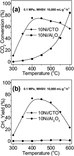 | ||
| Fig. 11 Catalytic activities for CO2 methanation: (a) CO2 conversion and (b) CH4 yield. | ||
As we know, the family of perovskite-type oxides has many members, including BaTiO3, SrTiO3, MgTiO3, LaNiO3, and so on. Based on the above results, the use of CTO as a Ni catalyst support may not be the best choice. Thus, more exploration is needed to seek better perovskite oxide supports for methanation catalysts with much high activity and stability in our future work.
4. Conclusions
In this work, we report the preparation and characterization of perovskite CTO supported Ni catalysts with low NiO loadings for CO methanation. It reveals that the Ni/CTO catalysts show better catalytic performances than Ni/Al2O3 at 0.1 MPa and 3.0 MPa, respectively. Nearly 100% CO conversion and 85% CH4 selectivity can be achieved over the 10Ni/CTO catalyst (NiO loading: 10 wt%) under 0.1 MPa, at a WHSV of 10000 mL g−1 h−1 and a H2/CO feed ratio of 3. A life time test at 3.0 MPa and 600 °C demonstrates that the Ni/CTO catalyst maintains its good stability after a 50 h reaction. It is found that the main factors which account for the better catalytic activity of Ni/CTO than Ni/Al2O3 are the weak interaction between Ni and CTO support, the proper Ni particle size (resistance to carbon deposition), the superior stability and non-acidic nature of CTO. This work demonstrates that the perovskite oxide CTO would be an appropriate Ni catalyst support for CO and CO2 methanation process.
Acknowledgements
The authors gratefully acknowledge the support from the Hundred Talents Program of the Chinese Academy of Sciences (CAS), State Key Laboratory of Multiphase Complex Systems of China (No. MPCS-2009-C-01), National Key Technology R&D Program of China (No. 2010BAC66B01) and National Key Basic Research Program of China (No. 2011CB200906). F. Gu is grateful to the support of K. C. Wang Post-doctoral Fellowships of the CAS and China Postdoctoral Science Foundation (No. 20100480026).Notes and References
- M. Vannice, Catal. Rev. Sci. Eng., 1976, 14, 153 CAS.
- V. Ponec, Catal. Rev. Sci. Eng., 1978, 18, 151 CAS.
- J. Gao, Y. Wang, Y. Ping, D. Hu, G. Xu, F. Gu and F. Su, RSC Adv., 2012, 2, 2358 RSC.
- Y. Yu, G. Q. Jin, Y. Y. Wang and X. Y. Guo, Fuel Process. Technol., 2011, 92, 2293 CrossRef CAS.
- Y. Wang, R. Wu and Y. Zhao, Catal. Today, 2010, 158, 470 CrossRef CAS.
- S. D. Senanayake, J. Evans, S. Agnoli, L. Barrio, T. L. Chen, J. Hrbek and J. A. Rodriguez, Top. Catal., 2011, 54, 34 CrossRef CAS.
- D. Hu, J. Gao, Y. Ping, L. Jia, P. Gunawan, Z. Zhong, G. Xu, F. Gu and F. Su, Ind. Eng. Chem. Res., 2012, 51, 4875 CrossRef CAS.
- D. C. Gardner and C. H. Bartholomew, Ind. Eng. Chem. Prod. Res. Dev., 1981, 20, 80 CrossRef CAS.
- J. Gao, C. Jia, J. Li, F. Gu, G. Xu, Z. Zhong and F. Su, Ind. Eng. Chem. Res., 2012, 51, 10345 CrossRef CAS.
- K. O. Xavier, R. Sreekala, K. K. A. Rashid, K. K. M. Yusuff and B. Sen, Catal. Today, 1999, 49, 17 CrossRef CAS.
- S. L. Ma, Y. S. Tan and Y. Z. Han, J. Nat. Gas Chem., 2011, 20, 435 CAS.
- A. E. Aksoylu, A. N. Akin, S. G. Sunol and Z. I. Onsan, Turk. J. Chem., 1996, 20, 88 CAS.
- E. Kis, R. MarinkovicNeducin, G. Lomic, G. Boskovic, D. Z. Obadovic, J. Kiurski and P. Putanov, Polyhedron, 1998, 17, 27 CrossRef CAS.
- M. V. Twigg and J. T. Richardson, Appl. Catal., A, 2000, 190, 61 CrossRef CAS.
- A. Zhao, W. Ying, H. Zhang, H. Ma and D. Fang, Catal. Commun., 2012, 17, 34 CrossRef CAS.
- J. R. Rostrup-Nielsen, K. Pedersen and J. Sehested, Appl. Catal., A, 2007, 330, 134 CrossRef CAS.
- I. Levin and D. Brandon, J. Am. Ceram. Soc., 1998, 81, 1995 CrossRef CAS.
- M. A. Pena and J. L. G. Fierro, Chem. Rev., 2001, 101, 1981 CrossRef CAS.
- K. Urasaki, Y. Sekine, S. Kawabe, E. Kikuchi and M. Matsukata, Appl. Catal., A, 2005, 286, 23 CrossRef CAS.
- J. Gao, L. Jia, W. Fang, Q. Li and H. Song, J. Fuel Chem. Technol., 2009, 37, 573 CrossRef CAS.
- R. N. S. H. Magalhaes, F. S. Toniolo, V. T. da Silva and M. Schmal, Appl. Catal., A, 2010, 388, 216 CrossRef CAS.
- T. Hayakawa, H. Harihara, A. G. Andersen, K. Suzuki, H. Yasuda, T. Tsunoda, S. Hamakawa, A. P. E. York, Y. S. Yoon, M. Shimizu and K. Takehira, Appl. Catal., A, 1997, 149, 391 CrossRef CAS.
- K. Takehira, T. Hayakawa, H. Harihara, A. Andersen, K. Suzuki and M. Shimizu, Catal. Today, 1995, 24, 237 CrossRef CAS.
- K. Takehira, T. Shishido and M. Kondo, J. Catal., 2002, 207, 307 CrossRef CAS.
- J. M. Rynkowski, T. Paryjczak and M. Lenik, Appl. Catal., A, 1993, 106, 73 CrossRef CAS.
- K. Y. Koo, H. S. Roh, Y. T. Seo, D. J. Seo, W. L. Yoon and S. Bin Park, Int. J. Hydrogen Energy, 2008, 33, 2036 CrossRef CAS.
- P. Billik, M. Caplovicova, T. Turanyi, L. Caplovic and B. Horvath, Mater. Res. Bull., 2011, 46, 2135 CrossRef CAS.
- A. Duevel, E. Romanova, M. Sharifi, D. Freude, M. Wark, P. Heitjans and M. Wilkening, J. Phys. Chem. C, 2011, 115, 22770 CAS.
- J. Zhang, H. Y. Xu, X. L. Jin, Q. J. Ge and W. Z. Li, Appl. Catal., A, 2005, 290, 87 CrossRef CAS.
- S. M. Kim, Y. J. Lee, J. W. Bae, H. S. Potdar and K. W. Jun, Appl. Catal., A, 2008, 348, 113 CrossRef CAS.
- F. Meshkani and M. Rezaei, Catal. Commun., 2011, 12, 1046 CrossRef CAS.
- A. H. Zhang, J. Zhu and W. H. Duan, Surf. Sci., 2007, 601, 475 CrossRef CAS.
- A. Romero, M. Jobbagy, M. Laborde, G. Baronetti and N. Amadeo, Catal. Today, 2010, 149, 407 CrossRef CAS.
- I. Czekaj, F. Loviat, F. Raimondi, J. Wambach, S. Biollaz and A. Wokaun, Appl. Catal., A, 2007, 329, 68 CrossRef CAS.
- Z. Y. Hou, O. Yokota, T. Tanaka and T. Yashima, Appl. Catal., A, 2003, 253, 381 CrossRef CAS.
- J. Escobar, J. A. De Los Reyes and T. Viveros, Appl. Catal., A, 2003, 253, 151 CrossRef CAS.
- S. Holliday and A. Stanishevsky, Surf. Coat. Technol., 2004, 188, 741 CrossRef.
- R. B. Shalvoy, P. J. Reucroft and B. H. Davis, J. Vac. Sci. Technol., 1980, 17, 209 CrossRef.
- L. Salvati, L. E. Makovsky, J. M. Stencel, F. R. Brown and D. M. Hercules, J. Phys. Chem., 1981, 85, 3700 CrossRef CAS.
- N. Perkas, G. Amirian, Z. Y. Zhong, J. Teo, Y. Gofer and A. Gedanken, Catal. Lett., 2009, 130, 455 CrossRef CAS.
- Y. J. Huang, J. A. Schwarz, J. R. Diehl and J. P. Baltrus, Appl. Catal., 1988, 37, 229 CrossRef CAS.
- S. M. Fang, J. M. White, T. J. Campione and J. G. Ekerdt, J. Catal., 1985, 96, 491 CrossRef CAS.
- P. Mondal, G. S. Dang and M. O. Garg, Fuel Process. Technol., 2011, 92, 1395 CrossRef CAS.
- K. B. Kester and J. L. Falconer, J. Catal., 1984, 89, 380 CrossRef CAS.
- J. Lu, B. Fu, M. C. Kung, G. Xiao, J. W. Elam, H. H. Kung and P. C. Stair, Science, 2012, 335, 1205 CrossRef CAS.
- S. H. Kim, S.-W. Nam, T.-H. Lim and H.-I. Lee, Appl. Catal., B, 2008, 81, 97 CrossRef CAS.
- S. Takenaka, T. Shimizu and K. Otsuka, Int. J. Hydrogen Energy, 2004, 29, 1065 CrossRef CAS.
- P. Djinović, C. Galletti, S. Specchia and V. Specchia, Catal. Today, 2011, 164, 282 CrossRef.
- F. Su, J. Zeng, P. Bai, L. Lv, P. Guo, H. Sun, H. Li, J. Yu, J. Y. Lee and X. S. Zhao, Ind. Eng. Chem. Res., 2007, 46, 9097 CrossRef CAS.
- J. H. Kim, D. J. Suh, T. J. Park and K. L. Kim, Appl. Catal., A, 2000, 197, 191 CrossRef CAS.
- C. H. Bartholomew, Catal. Rev. Sci. Eng., 1982, 24, 67 CAS.
- J. Kopyscinski, T. J. Schildhauer and S. M. A. Biollaz, Fuel, 2010, 89, 1763 CrossRef CAS.
| This journal is © The Royal Society of Chemistry 2013 |