 Open Access Article
Creative Commons Attribution 3.0 Unported Licence
Salt melt synthesis of ceramics, semiconductors and carbon nanostructures
Xiaofeng Liu*, Nina Fechler and Markus Antonietti
Department of Colloid Chemistry, Max-Planck Institute of Colloids and Interfaces, Research Campus Golm, Postdam 14424, Germany. E-mail: xiaofeng.liu@mpikg.mpg.de; lxf_lxf@126.com; Fax: +49 (0)331 567 9502; Tel: +49 (0)331 567 9782
First published on 18th July 2013
Abstract
Materials synthesis in the liquid phase, or wet-chemical synthesis, utilizes a solution medium in which the target materials are generated from a series of chemical and physical transformations. Although this route is central in organic chemistry, for materials synthesis the low operational temperature range of the solvent (usually below 200 °C, in extreme 350 °C) is a serious restriction. Here, salt melt synthesis (SMS) which employs a molten inorganic salt as the medium emerges as an important complementary route to conventional liquid phase synthesis. Depending on the nature of the salt, the operational temperature ranges from near 100 °C to over 1000 °C, thus allowing the access to a broad range of inorganic crystalline materials and carbons. The recent progress in SMS of inorganic materials, including oxide ceramic powders, semiconductors and carbon nanostructures, is reviewed here. We will introduce in general the range of accessible materials by SMS from oxides to non-oxides, and discuss in detail based on selected examples the mechanisms of structural evolution and the influence of synthetic conditions for certain materials. In the later sections we also present the recent developments in SMS for the synthesis of organic solids: covalent frameworks and polymeric semiconductors. Throughout this review, special emphasis is placed on materials with nanostructures generated by SMS, and the possible modulation of materials structures at the nanoscale in the salt melt. The review is finalized with the summary of the current achievements and problems, and suggestions for potential future directions in SMS.
 Xiaofeng Liu | Xiaofeng Liu received his BS in 2004 and MS in 2007 from Nanjing University of Technology, and PhD degree in 2010 from Shanghai Institute of Optics and Fine Mechanics, Chinese Academy of Sciences. He then joined Prof. Hideo Hosono's group as a postdoctoral researcher in Frontier Research Centre, Tokyo Institute of Technology. Since April 2011, he has been an Alexander von Homboldt postdoctoral fellow with Prof. Markus Antonietti in the Department of Colloid Chemistry, Max-Planck Institute of Colloids and Interfaces. His current research focuses on the synthesis of carbon-based nanostructures using the salt melt route. |
 Nina Fechler | Nina Fechler studied nanostructure and molecular sciences at the University of Kassel and the Fraunhofer Institute for Applied Polymer Research in Potsdam/Golm (2005–2010) where she was working on thermoresponsive polymers under the supervision of Dr habil. Jean-François Lutz. She obtained her PhD degree from the Max-Planck Institute of Colloids and Interfaces in Potsdam/Golm (2010–2013) with Professor Markus Antonietti. During this time, she focused on porous carbon-based materials from ionic liquids for energy-related applications and contributed to the establishment of salts as versatile porogens. Currently, she is a postdoctoral fellow at the same institute where she works on supercapacitors and the extension of the salt approach also to other material classes. |
 Markus Antonietti | Markus Antonietti has studied Chemistry in Mainz and did his doctorate with Hans Sillescu. His habilitation about nanostructured polymer gels in 1990 fuelled his enthusiasm for complex materials. After a professorship in Chemistry at the University of Marburg he was appointed director of the Department of Colloid Chemistry at the Max-Planck Institute of Colloids and Interfaces in 1993. Markus Antonietti's contributions to the chemical community comprise many things, but first of all he is interested in the creativity in research. He loves to share and impart this passion. He likes cooking and loud music. |
1. Introduction
In the past decades, many discoveries in physics and chemistry have been triggered by the breakthrough in fabrication procedures that allowed unprecedented easy access to the desired materials and material structures. For instance, mechanical exfoliation of high quality graphene from graphite crystals allowed discoveries that resulted in a Physics Nobel Prize.1,2 Another example is the controlled synthesis of colloidal quantum dots using wet chemistry routes which unfolded the field of physics and chemistry of quantum confined semiconductors and resulted meanwhile in applications from optoelectronics to the biology fields.3–5From a chemistry point of view, material synthesis is of course the result of chemical transformations which can be performed in a gaseous, solid state or solution environment. Wet chemistry methods performed in solutions are usually the most favored, as they provide best reaction and heat control, sufficient reversible dynamics, and thereby facile pathways for the synthesis of diverse inorganic materials built up from metallic, ionic and covalent bonds. Compared to that, solid-state synthesis is dynamically very restricted, and mostly systems are driven with partially brute force to a thermodynamically stable state by applying high temperatures and very long reaction duration. This process thus faces major difficulties in the synthesis of intermediates that are only kinetically stable,6–8 which, for example, is especially true for all nanomaterials and low dimensional materials.
However, solution chemistry usually ends at around 200 °C, and even with high boiling solvents or solvothermal processes at around 350–400 °C (after that most solvents decompose or turn supercritical). This simply does not allow the synthesis of all compounds, especially not those with high covalency.9 Metallic or ionic materials crystallize easily under mild solvent conditions; while strong covalently bonded compounds can only be synthesized at mild temperatures at the expense of order and crystallinity. In this regard, a non-volatile solvent family, operational at high temperatures, is desired for development of more sustainable chemical syntheses at high temperatures.
Solution chemistry methods on the other hand are of course not restricted to organic solvents and water. The use of different types of “fluxes”, including low melting metals and salts, has in fact been extensively explored for the synthesis of metallic and non-metallic materials in the form of either single crystals or polycrystalline powders.10,11 Compared to solid state reactions for which the rates are usually seriously limited by the slow diffusion of the reactants, the flux method lowers the reaction temperature as it allows faster mass transfer transport in the liquid phase by means of convection and diffusion. For those solvent-based synthetic routes solvation is a crucial step, but molecular solvents hardly solvate many inorganics like metals and oxides. However, destabilization of metallic, ionic or covalent bonds by solvent interactions becomes possible at high temperatures in the presence of strong polarizing force which can be provided by salt melts – a pool of ionized cations and anions. On the other hand, as many salts by their nature dissolve in water, salt melt synthesis (SMS) has the advantage of easy isolation of the product. Salt melts have in fact a long history as a solvent in research as well as in industry. They have been used as reaction media for various organic and inorganic reactions,12–14 and also as flux for crystal growth. Practically, various salt melt systems have been widely applied as high temperature liquid electrolytes which are used in batteries,15,16 and in the electrolysis of refractory metals.17–19
This review here focuses on the research progress in inorganic materials synthesis with the salt melt route. Ionothermal synthesis in organic salts, commonly known as ionic liquids (ILs), will not be included, as this topic has been covered by extensive reviews.20,21 We will start from the introduction of some physical and chemical fundamentals of salt melts and the introduction of some useful salt melt systems, and afterwards discuss the materials obtained by SMS, in the sequence of oxides, non-oxides, semiconductors, covalent frameworks and carbon nanostructures. Only a few selected outstanding examples in each type of material will be discussed in detail, as an exhaustive presentation of all the accessed materials is impossible. A distinct focus lies on controlled nanostructures and nanophase materials obtained in salt melt and their structure modulation by SMS. The review will be finalized by giving some potential future directions for material synthesis by SMS.
2. General considerations for SMS
2.1 Physics and chemistry of salt melts
Before starting the SMS, it is important to select the right salt system. Therefore, some fundamental properties of the salt need to be discussed first, including the working temperature range, chemical reactivity, vapour pressure, etc.Most metals are soluble in their metal halides, and above a characteristic temperature the metal–salts systems are completely miscible. The solubility is related to many factors, including the atom size and electronegativity. For the same group of metals, the solubility increases with the molecular weight. For instance, the solubility of Mg in MgCl2 is only 1.1 mol%, while it increases to 16 mol% for Ca and to 25 mol% for Sr (at 1000 °C).12 The solubility also relates to the number of valence electrons for some metals. This is suggested by the fact that metal salts with a high oxidation state tend to exhibit higher solubility. The metal ions are believed to stabilize at an intermediate oxidation state, resulting in formation of sub-halides, such as the case of rare earth halide. The structure of the metal–metal halides systems is also distinct from system to system. For systems like Ba/BaCl2, molten metals can be present as very small droplets in the salt melt, forming a stable colloidal solution. For other systems, metals are believed to be ionized in the salt melt to metal ions (or poly-ions) and free electrons, which is supported by conductivity measurements of many rare earth halide–metal systems. With the decrease in the metal content, the systems undergo a steady transition from rather delocalized to localized electronic states.22–24
Many metal compounds like oxides are also soluble in salt melts at high temperatures, and many thermodynamic data have become available online or are retrievable from text books. Unfortunately, only a limited set of systems have been covered by the open data bases. The authors recommend using the hard–soft acid–base (HSAB) theory as a simple guidance for the prediction of the solubility. The interactions within the HSAB theory can be simplified as “hard, non-polarizable prefers hard; soft, polarizable prefers soft”. As salt melts are in general highly polarizing media, they prefer polarizable solutes. For instance, MgO is difficult to dissolve in both binary and multinary chloride systems (<0.05% at 800 °C) as it is rather hard, in contrast the solubility of the softer CaO in CaCl2 is higher than 15% at 800 °C. Strongly covalent oxides, such as SiO2, are difficult to dissolve with metal chlorides as the Si-centres are difficult to address by halide anions like Cl−. In such cases, metal fluorides are expected to be the best solvent as fluorine ions F− are strongly nucleophilic. Indeed, metal fluorides dissolve easily silica, while chlorides or bromides fail. In general, the solvation process in salt melts is rather complicated, but the old adage “similia similibus solvuntur” nicely serves for first trials.
For SMS, the separation of products from the salts in the final stage is crucial. Usually, it is performed by washing with water, while small amounts of salt can always be present in the final products. This is not only related to the water solubility of the salt, but rather due to the intrinsic interactions of the salts with the product, which even can result in intercalates or solid solutions. This high interaction of the solvent with the product is indeed one of the major potential drawbacks of the salt melt synthesis which need to be considered carefully in the quality control of the as-obtained products.
2.2 Useful salt melt systems
| Oxobase ↔ Oxoacid + O2− | (1) |
The oxide ion O2− is the simplest base, and the basicity of the melt is usually expressed as pO2− = –log m(O2−), as an analogue to pH. The magnitude of pO2− determines the reactions in the salt melt. For instance, under moderate pO2−, precipitation of TiO2 occurs through:
| Ti4+ + 2O2− → TiO2 | (2) |
With further increase in basicity (lower pO2−), the precipitated TiO2 can be re-dissolved into titanate anions:
| TiO2 + O2− → TiO32− | (3) |
Molten hydroxide, nitrate and sulphate can be regarded as bases and hence they are all oxidizing, as they can provide oxide ions O2− in most cases.
The use of highly oxidative anions like chlorate, although rarely reported, can also be explored for special purposes, for instance, to stabilize certain elements at their high oxidation state. However, the potential danger of explosion should be carefully evaluated before using such highly oxidizing salt in large amounts. In addition, the use of metal metalate salt melts can sometimes be a wise choice if the targeted compounds contain the same (or similar) metalate anions as building units.
The salt melt can also contain more than one type of anions, and in this sense the characteristics of the melt can be fine-tuned. This strategy is indeed often applied for the preparation of oxides in a melt containing, for instance, hydroxide and carbonate ions. The purpose is to adjust the acid–base equilibrium such that the melt favors the precipitation of the targeted products.
2.3 Economy and safety considerations
Most of the salt systems mentioned above are composed of non-precious and abundant elements. However, the cost of the salts still can be a relevant factor especially for large scale production. The use of cheap salts like NaCl and KCl is therefore much preferred, while Li salts are expensive and can only be applied for high value products. In such cases, the development of a salt recycling method becomes important and economically necessary.Regarding the safety issue, it is known that alkali metal and halide (except F) ions are non-toxic and direct skin-contact does not cause harmful effects. In handling metal fluorides, extreme care should be taken to avoid contact, as they can cause severe damage to human tissues. Acidic salts like AlCl3 and alkalis like KOH are also obvious corrosive substances. In addition, heavy metal salts, such as BaCl2, should also be processed with care as they are obviously harmful to the human body. After being melted, the melt of all these salts can be potential danger, not only because of the high temperature, but also due to the toxic gases released from the melt, such as NO2 and SO2. Therefore, the SMS has to be carried out in the presence of continuous ventilation; otherwise, the accumulated vapour can cause corrosion to the nearby instruments and human beings. It is recommended to perform SMS in specialized rooms or furnaces which are not used for other purposes. Before starting SMS for certain target compounds, the potential safety threat should be thoroughly assessed in each step of the experiments. Sometimes, misuse of chemicals or the container which is corroded by the salt melt can lead to disastrous consequences. The potential safety threat of the salt melt should never be underestimated before carrying out experiments.
3. Oxide ceramic powders from SMS
For the synthesis of oxides, oxysalts are natural choices, including hydroxide, nitrate, sulfate and carbonate anions. Oxides can in most cases be accessed by much simpler methods, such as hydrothermal or conventional colloid chemistry routes; the use of the salt melt method here, however, facilitates better crystallinity and contributes to a special texture of the products. Numerous types of oxides spanning from simple binary oxides to complex porous framework materials have been synthesized in different salt melt systems since the 1970s and have been reported in huge number of publications. The synthesis in salt melt for different materials may vary among different systems, but in general starts with precursor decomposition, or Lux–Flood acid–base reactions. We start their presentation from the simplest binary oxide and finish with the complicated zeolitic solids and complex oxides.3.1 Binary oxides
Different salt melt systems have been employed as the reaction medium for the synthesis of oxides of main group metals like Al, and also transition metal oxides in the form of micro-meter sized powders as well as low dimensional structures. Since the reported systems differ in the types of salt, precursors and synthetic procedures, we describe below from selected simple metal oxides and afterwards highlight the general principles regarding reaction mechanisms as well as texture formation in salt melt. Metal hydroxides and phosphates, which are also ionic combination of metal cations with non-metal anion groups, are also classified as binary systems and described in the following section.| Al2(SO4)3 + 6NO3− → Al2O3 + 3SO42− + 6NO2 + 3/2O2 | (4) |
It is found that the addition of stronger Lux–Flood bases, such as Na2O2 or Na2CO3, reduces the reaction temperature, because they provide oxide ions (O2−) in the melt at lower temperatures and therefore accelerate the reaction of Al3+ and O2− to precipitate Al2O3. Al2O3 can also be precipitated from AlCl3 by a similar reaction in nitrate.33 Synthesis of Al2O3 in inert salts like metal sulfate and chloride has also been carried out using Al(OH)3 as the precursor. It was found that Al(OH)3 releases H2O to give crystalline Al2O3 in the salt melt similar to other Al salt precursors.29
The morphology of α-Al2O3 synthesized from salt melt varies in different reports and is affected by the many processing parameters. Since Al–O bonding is of strongly covalent nature, the formation of well-defined Al2O3 crystallites requires a high crystallization temperature. From the transmission electron microscope (TEM) image, the Al2O3 powders obtained at a mild temperature (450 °C) in nitrite are composed of agglomerates of tiny crystallite of less than 5 nm in size, reflecting the sluggish crystallization kinetics and strong covalent nature of Al2O3 (Fig. 1a). As observed by different researchers, α-Al2O3 with well-defined crystalline morphology can be obtained at a high synthesis temperature irrespective of the type of salt melt used. Jin et al. synthesized α-Al2O3 platelets of sub-micrometer size from Na2SO4 melt at over 1200 °C,34 and they controlled the size of the platelets by addition of α-Al2O3 nanoparticles (NPs) as seeds, whose number also determines the number of nucleation sites (Fig. 1b). Other authors observed a similar hexagonal plate-shaped Al2O3 product but in different salt melt systems and from different precursors,35,36 implying that this morphology may relate inherently to the crystal structure of α-Al2O3 and Wulff's rules of face exposition.
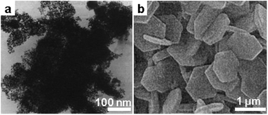 | ||
| Fig. 1 α-Al2O3 derived from different salt systems. (a) Typical TEM image of Al2O3 synthesized in molten NaNO2/KNO2 at 450 °C from Al2(SO4)3. (Reproduced from ref. 32 with permission from The Royal Society of Chemistry.) (b) Scanning electron microscope (SEM) image of Al2O3 platelets synthesized by seeded growth from Al2(SO4)3 in Na2SO4 at 1200 °C. (Reprinted with permission from ref. 34. Copyright 2004 John Wiley and Sons.) | ||
| SnCl2 + 2NO3− → SnO2 + 2Cl− + 2NO2 | (5) |
In the presence of a stronger Lux–Flood base, such as nitrite, the reaction is accelerated and therefore the precipitation temperature can be reduced. In contrast, the addition of chloride or bromide to the melt stabilizes the precursor as the oxide ions are diluted. Depending on the types of salts as well as other synthetic conditions, the produced SnO2 can be of different morphology. Using the salt mixture of LiNO3–LiOH containing H2O2, Guo et al. synthesized nanocrystalline powders of SnO2 composed of agglomerates of small crystallites (5 nm) at 300 °C (Fig. 2a).38 By heating phenanthroline-capped Sn NPs in the melt of KOAc at 320 °C,39 SnO2 nanowhiskers composed of small crystallites (<10 nm) were obtained. The crystallinity can be substantially improved by heating the same precursor in a NaCl–KCl mixture to over 800 °C, in which highly crystalline nanorods of 15 nm in diameter are produced, giving a capacitance of 1100 mA h g−1 as the anode for the Li-ion battery. Single crystalline nanorods of SnO2 have also been accessed with high yield by the decomposition of SnC2O4 capped with surfactants in the melt of NaCl at over 800 °C (Fig. 2b).40 The author claimed that the use of organic surfactant is crucial in the formation of rod-like morphology due to preferred growth of SnO2 in the ionic melt.
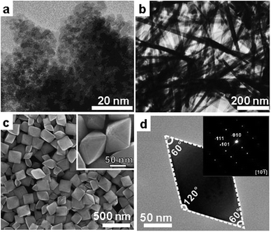 | ||
| Fig. 2 SnO2 nanostructures by SMS. (a) TEM image of SnO2 NPs synthesized from SnCl2 in LiOH at 300 °C. (Reproduced from ref. 38 with permission from The Royal Society of Chemistry.) (b) TEM image of SnO2 nanowires produced from SnC2O4 in NaCl at 810 °C (Reprinted with permission from ref. 40. Copyright 2003 Elsevier.) (c) SEM and (d) TEM images of SnO2 octahedrons synthesized from SnCl4 in tetramethylammonium hydroxide. (Reprinted with permission from ref. 41. Copyright 2012 John Wiley and Sons.) | ||
With the SMS route, it is also possible to realize crystal facet engineering for SnO2 nanocrystals (NCs). In a recent work of Wang et al. carried out in a basic organic salt, the author observed that the outer surface of the produced SnO2 NCs evolved from low energy (like {101}) facets to high energy facets (like {111}) through the adjustment of the amount of organic salt. Under optimized conditions, pure SnO2 octahedrons were obtained, which exhibited a significantly enhanced catalytic activity and selectivity for CO oxidation (Fig. 2c and 2d).41
| K2TiF6 + 4NO3− → TiO2 + 4NO2 + O2 + 2K+ + 6F− | (6) |
In a similar fashion, increasing the basicity of the melt by addition of basic oxides, such as Na2O2, promotes the precipitation and allows the formation of TiO2 at a lower temperature. TiO2 with anatase structure can also be precipitated from TiOCl2 in ammonia nitrate at a temperature of 400–500 °C by the following reaction:43
| TiO2+ + 2NO3− → TiO2 + 2NO2 + 1/2O2 | (7) |
In a detailed investigation by Afanasiev et al., porous TiO2 structures with the crystal size ranging from less than 10 nm to around 30 nm were synthesized. The authors found that the presence of a nitrogen-containing stabilizer (urea, melamine and ammonium oxalate) added during synthesis influenced the evolution of the morphology as well as the photocatalytic properties of the resulting samples (Fig. 3a and b). In another report, titanium hydroxide was used as the precursor and the mixture of NaCl and Na2HPO4·2H2O was employed as the salt medium.44 It was found by the authors that particles prepared without salt are strongly agglomerated and fused, while finely divided particles are prepared within the salt melt route. Moreover, temperature has a crucial influence on both the crystal structure as well as the morphology of the product. Anatase particles and rods in a small fraction are obtained at a temperature of 725 °C, which is below the eutectic point of the salt system employed. At temperatures higher than eutectic, the obtained products are of pure rutile phase with rod-like structure (Fig. 3c and d), suggesting again a preferred growth direction in the polar ionic melt.
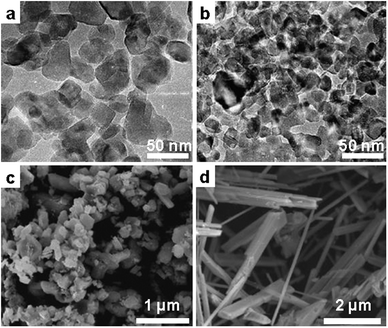 | ||
| Fig. 3 TEM images of TiO2 NCs produced from TiOCl2 in NH4NO3 (a) without additive, (b) in the presence of (NH4)2C2O4. (Reprinted with permission from ref. 43. Copyright 2010 Elsevier.) (c) SEM image of TiO2 NCs and (d) nanorods synthesized from TiCl4 in molten NaCl in the presence of NaH2PO4 at 725 °C and 825 °C, respectively. (Reprinted with permission from ref. 44. Copyright 2008 John Wiley and Sons.) | ||
| Zn2+ + 2NO3− → ZnO + 2NO2 + 1/2O2 | (8) |
Similar to the previous cases, the precipitation can be shifted to lower temperatures through increasing the basicity of melt via the addition of oxide ion donors, such as Na2O2. Because of its technical relevance, SMS of ZnO was pursued much further to obtain control of the microstructures at the nanoscale. In the first example, Afanasiev et al. studied the structural evolution of ZnO in the melt of KNO3/KCl at the temperature of 500 °C. Hollow hexagonal tubes were obtained, which were explained by oriented attachment of the intermediate small ZnO crystallites and a Kirkendall effect (Fig. 4a–d).45 The process allowed the production of ZnO with different structures from plates to tubular structures of controllable length. In another example, Jiang et al. synthesized ZnO nanowires with unusual growth directions of 〈102〉 and 〈100〉 in the melt of LiCl (Fig. 4e and f).46 The authors ascribed the observed abnormal growth to the interaction of the ionic species like Li+ and Cl− with the polar crystal planes of {101} and {001}, making them low energy faces. Moreover, the same group found that the ZnO NCs produced in LiNO3 have all the polar surfaces exposed. This is because the surface energy for the polar surfaces is reduced as a result of the strong electrostatic interactions between the salt melt and the surface atoms, potentially keeping dangling bonds.
![ZnO nanostructures by SMS. (a) Schematic illustration of the growth of ZnO hollow nanotubes in salt melt. (b–d) SEM images of ZnO nanostructures observed after different growth durations 0.5 h, 2 h and 8 h in KNO3/KCl melt. (e) TEM image of ZnO nanobelts from decomposition of Zn(Ac)2 in LiCl at 615 °C. (f) Structure of wurtzite ZnO viewed along the [1,0,−1.7] direction, giving the outer planes of the nanowires. (Reprinted with permission from ref. 45 and 46. Copyright 2012, 2005 American Chemical Society.)](/image/article/2013/CS/c3cs60159e/c3cs60159e-f4.gif) | ||
| Fig. 4 ZnO nanostructures by SMS. (a) Schematic illustration of the growth of ZnO hollow nanotubes in salt melt. (b–d) SEM images of ZnO nanostructures observed after different growth durations 0.5 h, 2 h and 8 h in KNO3/KCl melt. (e) TEM image of ZnO nanobelts from decomposition of Zn(Ac)2 in LiCl at 615 °C. (f) Structure of wurtzite ZnO viewed along the [1,0,−1.7] direction, giving the outer planes of the nanowires. (Reprinted with permission from ref. 45 and 46. Copyright 2012, 2005 American Chemical Society.) | ||
| MOx + O2− → MOx+12− | (9) |
Second, metal oxides can also be synthesized through the decomposition of unstable precursors at elevated temperatures in salt melt. This occurs when metal organic compounds (like metal oxalate) are used as precursors. In the third case, salt melt sometimes only provides a high temperature liquid environment for the crystallization of the oxide from poorly crystalline precursors; here, no chemical reaction takes place but only a dissolution–recrystallization mechanism is involved.
| Oxide | Precursors/salt | Synthesis temperature | Product characteristics | Ref. |
|---|---|---|---|---|
| MgO | MgSO4 or MgCl2/NaNO3–KNO3 or NaNO2–KNO2 | 450–600 °C | NCs, 50 nm | 54 |
| α-Fe2O3 | Fe2O3/NaCl | 820 °C | Single-crystalline R–Fe2O3 rhombohedra | 55 |
| NiO | NiSO4/NaCl | 820 °C | Fibres, diameter: 1–2 μm, length: 100 μm | 56 |
| Ni/NaNO3–KNO3 | — | NCs, 2.6–3.1 nm | 57 | |
| Co3O4 | Co(NO3)2/LiNO3 | 400 °C | Submicro-octahedron | 58 |
| CuO | CuCl2/NaOH–KOH | 200 °C | Flower-shaped nanostructure | 59 |
In2O3![[thin space (1/6-em)]](https://www.rsc.org/images/entities/char_2009.gif) : :![[thin space (1/6-em)]](https://www.rsc.org/images/entities/char_2009.gif) Ni Ni | InOOH/LiNO3 | 300–500 °C | NCs, <100 nm | 60 |
Y2O3![[thin space (1/6-em)]](https://www.rsc.org/images/entities/char_2009.gif) : :![[thin space (1/6-em)]](https://www.rsc.org/images/entities/char_2009.gif) Er Er | Y(NO3)3/NaNO3–KNO3 | 500 °C | NCs, <100 nm | 61 |
CeO2![[thin space (1/6-em)]](https://www.rsc.org/images/entities/char_2009.gif) : :![[thin space (1/6-em)]](https://www.rsc.org/images/entities/char_2009.gif) Ba Ba | CeO2–BaCO3/NaOH–KOH | 200 °C | Nanowires | 62 |
| ZrO2 | ZrOCl2/NaNO3, KNO3 | 550 °C | Nanowires | 63 |
| La(CH3COO)3 + 3OH− → La(OH)3 + 3CH3COO− | (10) |
Interestingly, the obtained products are uniform, ultra-long belts with a thickness of around 10 nm (Fig. 5a–d). This observation suggested preferred growth along the c-axis for La(OH)3 in the hydroxide melt. More importantly, the nanobelts were nicely retained after conversion to La2O3 by calcination at high temperatures (Fig. 5e and f), pointing a promising route for the production of oxide one-dimensional (1D) nanostructures. It can be expected that 1D hydroxides and oxides of other metals with similar chemical characters could also be accessible in a similar fashion.
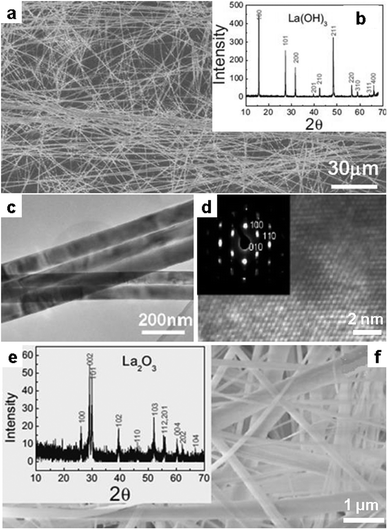 | ||
| Fig. 5 La(OH)3 nanobelt produced in the melt of NaOH/KOH at 200 °C from La(Ac)3 observed by (a) SEM image, (b) XRD pattern, (c) TEM and (d) high resolution TEM (HR-TEM) images. (e) XRD and (f) SEM image of the La2O3 nanobelts by thermal decomposition of La(OH)3 at 690 °C. (Reprinted with permission from ref. 64. Copyright 2007 John Wiley and Sons.) | ||
| RE3+ + PO43− → REPO4 (RE: trivalent rare earth cation) | (11) |
Indeed, the precipitation of LaPO4 was observed at a temperature higher than 350 °C for instance in the chloride melt containing LaCl3 and NH4H2PO4.65 Based on in situ and ex situ solid state nuclear magnetic resonance (NMR) the authors confirmed that the formation of LaPO4 in the melt of LiCl/KCl is not straightforward, but involved several intermediate phases. Furthermore, the formation of LaPO4 relied on a moderate O2 partial pressure, and too high or too low O2 partial pressure does not result in the desired product. Besides the influence of O2, the obtained precipitation is also affected by the composition of the melt. It was found that for the same RE and phosphate precursor, LiCl/KCl favored the formation of single phosphate REPO4, while NaCl/KCl usually results in double alkali metal rare earth phosphate A3RE(PO4)2.66 This investigation shows that various parameters must be carefully tuned in order to get the desired phosphates.
Similar to RE phosphate, ternary bi-metal phosphates of different compositions have also been precipitated. In molten nitrate, it was found that various metal phosphates can be obtained by reacting metal salts precursors with NH4H2PO4 in sodium or potassium nitrate melt at temperatures of 400–550 °C.66 In these systems, the components of the salt melt participate in the reactions and provide alkali metal atoms for the final products. Some of the technically important products synthesized include KTP (KTiOPO4) and a series of ABPO4 phases (A: alkali metal, B bivalent metals). Since some of the bimetal phosphates have a lamellar crystal structure, the salt melt-derived samples developed in many cases show layered textures (Fig. 6).67
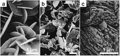 | ||
| Fig. 6 SEM images of different phosphates precipitated in NaNO3 at 500 °C from the salts of the different metal elements: (a) Na2Zr(PO4)2, (b) NaBaPO4 and (c) NaCaPO4. (Reprinted with permission from ref. 67. Copyright 1999 American Chemical Society.) | ||
Besides the above orthophosphates which do not contain P–O–P bonds, polyphosphates must be introduced here which can be regarded as the polymeric form of monophosphate. It is known that the basic structure unit PO4 (and SiO4) tetrahedrons tend to condense to form polymeric anions, in which oxygen serves as the bridge to connect adjacent PO4 units.68,69 This condensation process is controlled by many factors, such as temperature and pH value (in aqueous solution). The chemistry of phosphate has been extensively investigated in the last century and it is beyond the scope of this review.70,71 The process of SMS has also provided access to some of the polyphosphates.72–75 For instance, single crystal of LiNdP4O10 was synthesized in LiPO3 flux from Li2CO3, Nd2O3 and NH4H2PO4. In these reported processes for polyphosphates growth by SMS, the melt serves as flux and also reagent that provides building blocks for the products.
3.2 Ternary and multinary oxides
For the past 50 years, the SMS route has been extensively employed for the synthesis of ternary and multinary oxides which far outnumber binary oxide systems. Since huge numbers of reports have been published we can only pick up a few outstanding cases to represent each catalog of materials introduced below.| Ba2+ + TiO2 + 2OH− → BaTiO3 + H2O | (12) |
The same oxide has been synthesized by Wong et al. in chloride (NaCl) from a different precursor (Barium oxalate, BaC2O4) in the presence of nonionic surfactant (nonylphenyl ether). At the reaction temperature of 825 °C, BaTiO3 nanowires were obtained, in contrast to SrTiO3 where only nanocubes were formed; however, they have the same cubic crystal structure (Fig. 7e and f).77 At such high temperatures the organic surfactant is completely decomposed, while the results point out that its presence even at low temperature is relevant for the formation of the final structure. Later, the authors synthesized a solid solution of Ba1−xSrxTiO3 under the same conditions, and the products were on the whole rather irregular agglomerate NPs (<100 nm), implying that the role of surfactant might not be trivial.78 The results obtained by different authors differ greatly probably due to the different salts, precursors and processing conditions employed. In a similar salt system (NaCl/KCl), Deng et al.79 synthesized single crystalline nanowires of BaTiO3 from Ba oxalate and TiO2 at 950 °C without the use of surfactant (Fig. 7g and h). These authors showed that the process can be easily extended to the synthesis of single crystalline nanostripes of SrTiO3 and PbTiO3. For all the references introduced above, the authors all claimed the obtained products are stoichiometric ABO3 compounds. However, in a separate research carried out by Rørvik et al. using NaCl as flux,80 titanium oxide-rich compounds like BaTi2O5/BaTi5O11 and Na2Ti6O13 have been found as secondary phases in all the received products, indicating the loss of heavy metals (Ba, Sr or Pb) during synthesis. This is, as the authors suggest, due to the formation of volatile heavy metal chlorides through the reaction between Ba precursors and the chlorides melt. This work presents us a clear example of to what extent the evaporation loss of precursors affects the stoichiometry of the products in salt melt synthesis. This is indeed a serious point of consideration for SMS when the targeted compound contains volatile elements or if volatile chemicals can be evolved in the melt. The loss of ingredients can easily occur, especially for systems containing heavy metals.
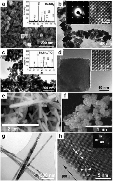 | ||
| Fig. 7 BaTi(Sr)O3 nanostructures synthesized in different salt systems. (a–d) BaTiO3 NCs synthesized in molten NaOH/KOH at 200 °C from BaCl2 and TiO2. (a and c) SEM and (b and d) TEM images of BaTiO3 and BaTi1−xSrxO3 NCs. The insets in (a and c) are XRD patterns, and in (b and d) are HRTEM images. (Reprinted with permission from ref. 76. Copyright 2006 American Chemical Society.) (e) SEM images of BaTiO3 nanowires and (f) SrTiO3 nanocubes synthesized in NaCl at 820 °C in the presence of surfactant. (Reprinted with permission from ref. 77. Copyright 2003 American Chemical Society.) (g) TEM and (h) HRTEM images of BaTiO3 nanobelts synthesized in NaCl/KCl at 950 °C. (Reproduced from ref. 79 with permission from The Royal Society of Chemistry.) | ||
| Li+ + Co2+ + 3NO3− → LiCoO2 + 3NO2 + 1/2O2 | (13) |
The reaction can be promoted in the presence of a stronger base KOH, which oxidizes Co2+ to Co3+ and afterwards precipitates LiCoO2via:
| Li+ + Co3+ + 4OH− → LiCoO2 + 2H2O | (14) |
Regarding electrochemical performance, the results indicate that products obtained at a higher temperature (850 °C) are larger crystals (Fig. 8b) with a higher capacity (up to 180 mA h g−1) due to the formation of over-stoichiometric Li1+xCoO2. Similar results are confirmed for LiCoO2 synthesized in a different melt system (LiCl/Li2CO3), in which the sample treated at a higher temperature (900 °C) showed an initial capacity of 150 mA h g−1 and much better cyclic stability, as compared to only 50 mA h g−1 capacity and fast decay for the sample treated at 600 °C.82 The same compound with a “dense-rose” texture was obtained in a pure hydroxide melt (CsOH, KOH and LiOH) at a very low temperature (200 °C).83 In this system, an interesting microstructural evolution of the intermediates from hexagonal plates to packed balls was observed, revealing a dissolution–oxidation–precipitation mechanism (Fig. 8c and d). The author thus believed this microstructure is beneficial for the superior electrochemical performance, especially at a high discharging rate.
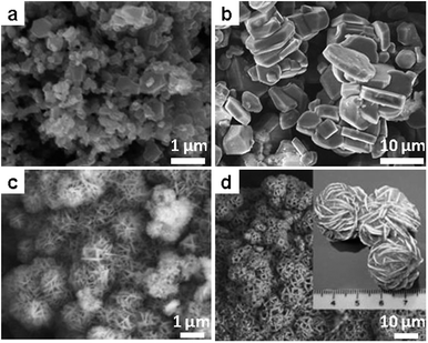 | ||
| Fig. 8 LiCoO2 nanostructures by SMS. (a and b) SEM images of LiCoO2 particles synthesized from LiCl and Co(NO3)2 in LiNO3 at 650 °C and 850 °C. (Reprinted with permission from ref. 81. Copyright 2005 Elsevier.) (c and d) SEM images of the “desert rose” shaped LiCoO2 nanostructures synthesized in hydroxide melt at 200 °C for 24 h and 48 h. (Reprinted with permission from ref. 83. Copyright 2008 John Wiley and Sons.) | ||
The spinel-type LiMn(Ni)2O4 is another important cathode material with potentially high operating voltage. In a melt of LiCl and LiOH,84 the precipitation of LiMn1.5Ni0.5O4 easily occurs from the precursors of MnOOH and Ni(OH)2 at a temperature of 700–900 °C. In this system, however, the formation of other Mn-containing binary oxides (like Mn3O4) is also thermodynamically possible.85 Guiding the system to deposit the desired Li manganite therefore requires careful control of several parameters, including the atmosphere and ratios of the precursors. The obtained spinel type LiMn2O4 powders are composed of primarily micrometer-sized octahedral crystallites, otherwise rather typical for crystals with cubic symmetry, which is also found in a more recent work.86 The results indicate that the reaction temperature should be carefully selected in order to optimize the product with respect to electrochemical performance. Low synthesis temperature in salt melt cannot ensure the sufficient crystallinity required for cyclic charging–discharging stability, while high synthesis temperature leads to densification which almost deactivates the material. The same temperature dependence of performance is observed also in other electrode materials and is mechanistically understandable. In another approach, Chang et al.87 first precipitated transition metal precursor TmOOH (Tm: transition metal) in aqueous solution in room temperature to form spherical particles, and afterwards calcined the metal precursor within a Li salt melt (LiOH–LiNO3) up to 800 °C to get the target spinel-type compounds. Their result showed that the spherical morphology of the precursor is nicely retained after synthesis, demonstrating the potential of using a template for structural control in the salt melt.
Recently, LiFePO4 has emerged as a popular and competitive candidate cathode material for Li-ion batteries due to its lower cost and high capacity. Since it is a quaternary oxide system, it is difficult to control the phase composition by conventional solid state reaction. The salt melt route provides an easy and cost-efficient access to this compound. In an early attempt,88 the mixture of raw materials of Li2CO3, FeC2O4 and NH4H2PO4 was first sintered at 450 °C, and then the sintered powders were used as precursor and treated in KCl at 750 °C. The obtained product LiFePO4 with the olivine structure showed spherical morphology and near-theoretical capacity (130.3 mA h g−1). It was later revealed from another investigation that treatment in KCl melt not only facilitates a more rapid crystal growth, but also enhances the textural packing density of the product, which are both beneficial for electrochemical application.89
Apart from the previous popular families, new oxide cathodes for Li-ion batteries with better performance are continuously developed. From the synthetic viewpoint, salt melt can of course provide efficient routes to access these materials, as exemplified further by Li4Ti5O12 and Li2FeSiO4.90–92
| Formula | Precursors | Salt systems | Synthesis temperature and products | Ref. |
|---|---|---|---|---|
| a Eutectic compositions. | ||||
| LaMO3 M = Al, Sc, Cr, Mn, Fe, CO, Ni, Ge or In | (a) MSO4, La(NO3)3, La2O3; (b) transition metal oxides, nitrate and La2(CO3)3; (c) metal nitrate | (a) NaNO3/KNO3a containing NaNO2 and Na2O2 as additive; (b) Li2CO3/Na2CO3 (c) NaNO2 or NaNO3/KNO3 | (a) 500–900 °C micro or nanocrystalline powders; (b) 650 °C, micrometer crystals; (c) 450–850 °C, nanocrystalline powder | (a) 93 (b) 94 (c) 95 |
| Pb(MNb3)O3 M = Mg, Fe, Zn, Ni, Co | (a) Metal oxides; (b) metal oxides; (c) BaCO3 and other metal oxides | (a) Li2SO4/Na2SO4 or NaCl/KCl or LiCl/NaCl; (b) NaCl/KCl; (c) NaOH/KOHa | (a) 750–900 °C, nanocrystalline powders; (b) 700–900 °C; (c) 350–500 °C | (a) 96 (b) 97 (c) 98 |
| ReFeO3 Re = La, Pr, Nd | Re oxides, and Fe(C2O4)2 | NaOH | 400 °C, micrometer cubic crystals | 99 |
| AeTm12O9 Ae = Sr or Ba Tm = Cr or Fe | Metal oxides | NaCl/KCl | 800–1100 °C micrometer or nanocrystalline powders | 100 |
| Na(La)TaO3 or Na(K)TaO3 | (a) Na2CO3, T2O5; (b) Na2CO3, K2CO3, Ta2O5 | (a) Na2SO4/K2SO4; (b) NaCl/KCl | (a) 900 °C, nanocrystalline powders; (b) 100–500 nm particles | (a) 101 (b) 102 |
| K2Nb8O21; NaNbO3; Ca(NbO3)2 | Nb2O5 | KCl, NaCl or CaCl2 | 800–820 °C nanorods of different length | 103 |
| ReTaO4 Re = Gd, Y, Lu | Metal oxides | LiCl, Li2SO4, or Na2SO4 | 610–1200 °C | 104 |
| BaTmO4 Tm = Mo or W | BaCl2, Na2MoO4 or Na2WO4 or (NH4)6Mo7O24·4H2O | KNO3 or NaNO3 | 400–550 °C micrometer crystals | 105 |
| AeTmReO6 Ae = Sr or Ba Tm = Fe or Cr | Metal oxides | NaCl/KCl | 750–800 °C 50 nm to over 1 μm | 106 |
| Ca2SiO4 or Ca3SiO5 | CaCO3 and SiO2 | NaCl | 908–1140 °C micrometer crystals | 107 |
| 9Al2O3·2B2O3 | Al(OH)3 or Al2(SO4)3 and B(OH)3 | KCl or K2SO4 | ∼1100 °C whiskers | 108 |
The first example to be introduced is the hydroxyapatite [HAP, Ca10(PO4)6(OH)2], which is a biomaterial of use in repairing bones and teeth. Growth of crystalline HAP particles has been realized in LiNO3 at 260 °C from an intermediate precursor prepared from CaCl2 and K2HPO4 in aqueous solution.109 The obtained powders are nanocrystalline (30–40 nm) with irregular particle shapes. Since the salts are polar compounds and therefore absorb microwave, the use of microwave heating during SMS also yields HAP particles as well as micron-sized rods.110 In another work, it was demonstrated that in the melt of K2SO4, NPs of HAP which served as seeds can be completely converted to whiskers with controllable size (Fig. 9a and b).111
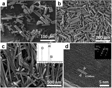 | ||
| Fig. 9 Whiskers of complex oxides by SMS. (a and b) SEM images of HPA whiskers produced by seeded growth in K2SO4 at 1300 °C. (Reprinted with permission from ref. 111. Copyright 2001 John Wiley and Sons.) (c) SEM and (d) HRTEM images of mullite whiskers synthesized in a B2O3 doped molten salts system. (Reproduced from ref. 116 with permission from The Royal Society of Chemistry.) | ||
Mullite is another example of a complex aluminum silicate with strongly anisotropic crystal structure, and it always crystallizes into one-dimensional whiskers in a suitable environment. Hashimoto et al. of Nagoya Tech. in Japan first112,113 reported the synthesis of mullite whiskers in the melt of K2SO4 from Al2(SO4)3 and silica. The reactions to form Mullite are believed to occur through the following three steps:
| Al2(SO4)3 + 3K2SO4 → 2K3Al(SO4)3 | (15) |
| K3Al(SO4)3 + Al2(SO4)3 → 3KAl(SO4)2 | (16) |
| 6KAl(SO4)2 + 2SiO2 → 3Al2O3·SiO2 + 3K2SO4 + 9SO3 | (17) |
The product obtained at 1100 °C has a length of 2–5 μm and surface area of 136 m2 g−1, and the phase compositions as well as microstructures are found to depend on the synthesis temperature as well as the concentration of the precursors. In a series of later publications, Zhang et al. found that the mullite species obtained from the flux of Na2SO4 are quite precursor-dependent: only the combination of the amorphous silica and the Al2(SO4)3 or amorphous Al2O3 resulted in whisker-structured mullite.114–116 Moreover, the authors revealed that the presence of a small amount of B2O3 in the sulfate led to uniform mullite nanowires of 30–50 nm in diameter and around 1 μm in length (Fig. 9c and d).
Moving to a higher order of structural complexity, zeolites are nice examples that are thermodynamically metastable and adopt a porous framework structure built up from SiO4 and AlO4 units. For a long time, artificial zeolites of different characteristics have been accessible by other means, such as hydrothermal methods using templates. Park et al. showed that treatment in salt melt converted mineral waste (fly ash) to different types of zeolites (Fig. 10).117–119 Depending on the different combination of alkali (NaOH, KOH) and salt (NaNO3, KNO3, NH4NO3, NH4F), the obtained zeolite species can be single phase sodalite or cancrinite, or their mixtures. Fig. 10 shows an example of phase evolution throughout “zeolitization” of fly ash in NaOH/KOH from 150 °C to 350 °C. In this system the optimized range of reaction temperature is 250–350 °C for durations from 3 h to 12 h.120 Complete conversion in this system can be reached under those conditions, while the synthesis of single phase zeolite is still impossible. The products are always a mixture of sodalite and cancrinite, while the fraction of each phase is related to many factors, such as composition of the salt and precursors, and the processing conditions.
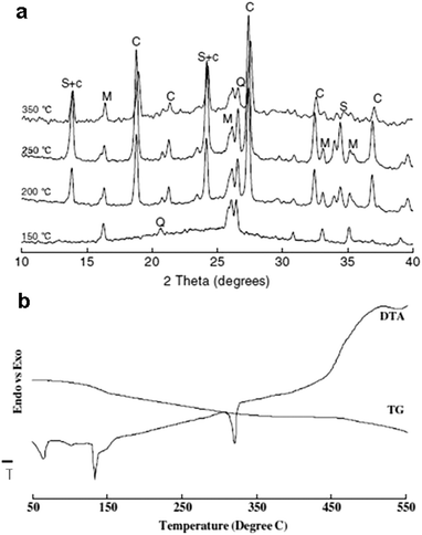 | ||
| Fig. 10 Zeolitization of fly ash in NaOH/KNO3 salt melt. (a) Phase evolution with increasing temperature examined by XRD. C: cancrinite; M: mullite; Q: quartz; S: sodalite. (b) TG-DTA traces of the mixture of fly ash and the salt (NaOH/KNO3). (Reprinted with permission from ref. 119. Copyright 2007 Springer.) | ||
4. Non-oxides from SMS
Oxides can in general be precipitated in salt melt based on simple acid–base chemistry, whereas the synthesis of non-oxides is a different story, partly because of their different redox chemistry as well as bonding character. They can be divided into two groups according to the covalent bonding strength: (i) compounds like borides, carbides and silicides, which are built up with strong metal–nonmetal covalent bonds which usually require a very high crystallization temperature; and (ii) chalcogenides, which are much weaker in bonding energy and can be in general accessed in mild temperatures. These materials are introduced in the following sections.4.1 Borides
Boron bonds strongly to transition metals, forming metal borides which are usually chemically robust and mechanically strong. Synthesis of borides by reaction from the elements is extremely difficult under a moderate temperature in salt melt, because boron is almost insoluble in most salts. To design a reasonable synthesis route, at least one of the precursors should be miscible with the melt to facilitate mass transport. CrB, as an example, was synthesized in AlCl3 in an autoclave at 650 °C from CrCl3, Na and amorphous boron by the following reaction:121| CrCl3 + B + 3Na → CrB + 3NaCl | (18) |
Metallic sodium in the above reaction serves as the reducing agent to generate Cr(0). Afterwards, CrB nucleates and grows into nanorods of 10–30 nm in diameter. The samples are nanocrystalline as indicated by the strong broadening of the XRD peaks. In the work reported by Portehault et al.,122 nanocrystalline borides of many transition and rare earth metals were synthesized in salt melt of eutectic LiCl/KCl. They applied a similar reduction–boronation process, in which metal chlorides were used as metal precursors and NaBH4 was used as the boron source and also the reducing agent. The reaction that took place in the salt can be simplified as:
| MClx + NaBH4 → MB + NaCl + HCl | (19) |
Different nano-borides are formed under different conditions. Fig. 11 shows two examples of nano-boride synthesized using this process. Furthermore, CaB6, CeB6, MoB4, NbB2, HfB2, FeB and Mn2B were synthesized, suggesting wide extendibility of this process. Without the use of reducing agent, the preparation of boride from oxide precursors can also be accomplished when electrons are supplied from electrodes, as exemplified by CeB6 production in molten fluoride.123
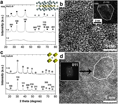 | ||
| Fig. 11 Metal borides synthesized in LiCl/KCl from metal chloride and NaBH4. (a) XRD pattern and (b) HRTEM image of NbB2 NCs. (c) XRD pattern and (d) HRTEM image of CaB6 NCs. (Reprinted with permission from ref. 122. Copyright 2011 John Wiley and Sons.) | ||
4.2 Carbides
Similar to borides, various metal carbides have also been accessed by salt melt synthesis but based on a different chemistry. Metal carbides, in the first place, can be synthesized directly from carbon and metal at high temperature. Such a direct route has been applied for W2C using the salt melt of NaCl/KCl at 1000 °C, giving particulate products with 300–500 nm in crystal size.124 In a similar system,125 polycrystalline carbide nanofibers of Ti, Zr, Hf, V, Nd and Ta were obtained from the reaction of metal powders with carbon nanotubes at 950 °C in the ternary salt melt of LiCl/KCl/KF (Fig. 12). The results confirmed the possibility of use of structural templating in molten salt synthesis, indicating very limited corrosion of the hard template by the salt. In addition to the binary systems, starting from elemental powders, the ternary carbide Cr2AlC was obtained in chloride melt in a moderate temperature range (900–1200 °C).126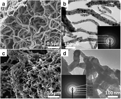 | ||
| Fig. 12 Metal carbide nanofibers by templated synthesis using carbon nanotubes in LiCl/KCl. (a and c) SEM and (b and d) TEM images of (a and b) TiC and (c and d) ZrC nanofibers. (Reprinted with permission from ref. 125. Copyright 2009 Elsevier.) | ||
Conversion of metal oxides to carbides in the presence of carbon is also thermodynamically possible and occurs through the so-called carbothermal reduction.127 In the salt melt solvent, the reaction occurs in the same way, yet the kinetics and the morphology of the products are greatly affected by the salt. TiC![[thin space (1/6-em)]](https://www.rsc.org/images/entities/char_2009.gif) :
:![[thin space (1/6-em)]](https://www.rsc.org/images/entities/char_2009.gif) N micrometer powders were synthesized by Chen et al.128 along this path at 1300 °C; a higher synthesis temperature leads to back oxidation of the product. For the system of TiO2–C–NaCl, the addition of Mg helps in the formation of TiC in an accelerated way by internal combustion which can heat the system to over 2000 °C.129 The combustion is the result of rapid reaction between Mg and TiO2:
N micrometer powders were synthesized by Chen et al.128 along this path at 1300 °C; a higher synthesis temperature leads to back oxidation of the product. For the system of TiO2–C–NaCl, the addition of Mg helps in the formation of TiC in an accelerated way by internal combustion which can heat the system to over 2000 °C.129 The combustion is the result of rapid reaction between Mg and TiO2:
| TiO2 + 2Mg → Ti + 2MgO | (20) |
TiC is formed afterwards through the reaction of Ti(0) with carbon. The combustion synthesis of metal carbides in salt melts was extended for the synthesis of other carbides, such as WC.130
4.3 Silicides
Metal silicides are of weaker covalent bonding strength compared to borides and carbides, and practically they can be accessed with much better crystallinity at mild temperatures lower than 1000 °C. For example, VSi2 was synthesized in the melt of NaCl/MgCl2 at only 650 °C, based on the following reaction:131| VCl4 + 2Si + 4Na → VSi2 + 4NaCl | (21) |
Here, a strong reducing agent, again Na, is used which is crucial for the process. The particles as observed from an electron microscope are 40–60 nm in size and oxidation resistant. In the second example, the silicide of Mn, Mn5Si3, was synthesized along a different reaction:132
| 5MnCl2 + 3Mg2Si → Mn5Si3 + 5MgCl2 + Mg | (22) |
In this system excess MnCl2 served as the reactant and also as salt melt. The resultant silicide showed interesting structure of nano-cages and bamboo-like nanotubes (Fig. 13), implying that a complicated nucleation and growth mechanism involving intermediates has been evoked.
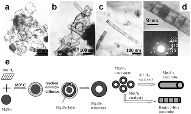 | ||
| Fig. 13 TEM images of (a and b) Mn5Si3 nanocages and (c and d) nanotubes synthesized from Mg2Si and MnCl2, in which MnCl2 was used as both reactants and flux. (e) Schematic illustration of the mechanism for nanocage and nanotube formation. (Reprinted with permission from ref. 132. Copyright 2004 Elsevier.) | ||
Similar to carbides as discussed previously, metal silicides can also be produced by the salt melt moderated combustion synthesis. Manukyana et al.133 synthesized MoSi2 by this route using MoO3, Si and Mg as reactants and NaCl as the salt. The use of NaCl as a diluting agent which slows down the combustion was found to play the key role in regulating the particle size below 1 μm.
4.4 Chalcogenides, polychalcogenides, thiophosphates and beyond
Compounds of metal with chalcogens and pnictogens show distinctive features different from oxides in their electronic and crystal structure, thus offering intriguing new properties. Apart from the well-known binary chalcogenide semiconductors (which will be introduced in the following section), many chalcogenides of transition metals are metallic conductors, which can be applied in electronics and catalysis. Examples of simple chalcogenides accessed by the salt melt route are in fact rare. Afanasiev and coworkers134 synthesized a set of sulfides from metal precursors and elemental sulfur in the Na2CO3 (or Li2CO3) melt. The reaction was carried out in glass reactors at mild temperatures (250–400 °C). In their experiment, different sulfides were produced depending on the type of salt and precursors. For instance, reaction of CoCl2 with S in Na2CO3 resulted in single phase CoS2, while for NiCl2 under the same reaction conditions the product is Na0.008NiS2. It was found that the alkali metal ions intercalated easily into the final product, especially for MoS3; in contrast Cl− anions were not detected. This is probably due to the huge difference in the size of alkali metal cations and halide anions.On the other hand, metal chalcogenides exhibit rich structural variations as chalcogen atoms tend to catenate and to coordinate with multiple metal atoms. Interesting properties disclosed for this group of materials stimulated continuing effort for the development of novel synthetic routes. Synthesis of these polychalcogenides by a high temperature process, such as solid state reaction, is impossible as the polychalcogen anions are not stable. Metal (poly)chalcogenides with low melt temperature represent an ideal flux which at the same time serves as precursors in the SMS. A series of such compounds have been grown from alkali metal polychalcogenides in the form of single crystals. The flux in these systems did not supply chalcogens as separated atoms, but only as polychalcogen anions which are then refound as building blocks in the products. Furthermore, the basicity as well as the oxidizing powder of the salt melt has been confirmed to be important factors which could determine the structure and phase composition of the products, for instance KAuSex. The materials developed from the chalcogenide melts are however not constrained to chalcogenide products; for instance the synthesis of thiophosphate could be performed in a K2S melt, as reported for ASnPS4 (A = K, Rb, Cs). Discussion of the synthetic chemistry and the crystal structure of these systems is far beyond the scope of this review, while these works point clearly that the use of new salt media, as exemplified here by metal chalcogenides, could open up completely new gates for materials synthesis and development.135,136
4.5 Metal and alloy nanostructures
Salt melt synthesis also allows easy access to a range of materials which are not included in the sections above. One case is the synthesis of metallic materials in chemically inert salt melt, such as fluorides or chlorides. From the chemical viewpoint, the synthesis of metallic materials can be easily realized through the reduction of metal precursors (such as oxides or halides) with a strong reducing metal, such as Al or Mg. Indeed, this strategy has been applied for a long time for the synthesis of alloys and ordered intermetallic compounds,137,138 in which the electrons are provided by the reductants.Contrary to our common viewpoint that oxide anions like NO3− are quite oxidizing, metal and alloys were also synthesized in such oxidizing melts. In a recent paper, Zhao et al.139 showed the synthesis of concave Pt NPs from tetra-amino platinum oxalate (Pt(NH3)4C2O4) in the melt of LiNO3–KNO3 containing KOH. The product was observed at a temperature below 200 °C, and the occurring reaction was described as:
| Pt(NH3)4C2O4 + 4KOH → Pt + 4NH3 + 2K2CO3 + 2H2O | (23) |
In the same salt melt, without the use of any reducing agent, the author can even synthesize a nano-alloy of Pt with Cu, which has in principle a stronger affinity for oxygen. The as-obtained PtxCuy alloy particles also showed concave contour, and the composition could be easily tuned.140 These results implied the high stability and on the other hand the limits of oxidation capability of these nitrate, hydroxide and carbonate anions, thus implying the possibility of their application as “inert” solvents in a broader range of synthesis.
5. Element and compound semiconductors
5.1 Group II–VI compound semiconductors
Binary metal chalcogenides are important semiconductors with bandgaps varying from near violet to the far infrared region. As a complementary method to the conventional wet-chemistry routes, the salt-melt route has been consistently applied to access these compounds, from sulfides to tellurides. Since chalcogenides crystallize easily at mild temperatures, salt systems with low working temperature are often applied. Here, organic salts seem to be a natural choice, which melt below 100 °C, and they have indeed served successfully as solvents for the growth of different chalcogenide semiconductors from bulk to nanostructures.141Inorganic salts with low melting point, such as nitrate and hydroxide, however, have also been employed as the solvents which can provide a suitable temperature window for the synthesis of metal chalcogenides, irrespective of their oxidizing nature. In a series of works, Hu and coworkers obtained nanostructure of metal chalcogenide semiconductors by the salt melt route, which they named the composite-hydroxide-mediated approach.142 The accessible materials by their approach include sulfides (ZnS, CdS and Bi2S3), selenides (CdSe and PbSe) and tellurides (CdTe and HgTe). These materials can be synthesized using metal salts and element powder of S (or Se, Te) or Na2Ch (Ch: chalcogen) as precursors at temperatures below 200 °C. It was found that metal sulfides can be generated in the hydroxide melt without the use of a reducing agent, while for selenide and telluride reducing agents such as hydrazine are usually needed. For different systems a similar reaction mechanism is believed to be involved. In the first step, a disproportionation reaction between the chalcogen and the hydroxide anions occurs by:143
| 3Ch + 6OH− → 2Ch2− + ChO32− + 3H2O | (24) |
Afterwards, metal chalcogenides precipitate by:
| Ch2+ + M2+ → MCh | (25) |
The product obtained from this approach usually showed rod or wire-like structures, suggesting the presence of a preferred crystal growth direction.144–147Fig. 14 presents the EM pictures of the typical metal chalcogenides nanostructures synthesized in hydroxide melt.
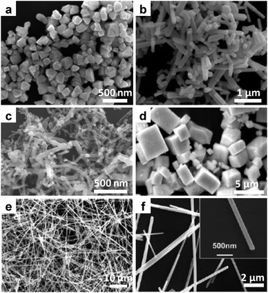 | ||
| Fig. 14 Metal chalcogenides semiconductor nanostructures synthesized in molten NaOH/KOH. (a and b) SEM images of CdSe NPs and nanorods synthesized from Cd(NO3)2 and elemental Se in the presence of (a) 2 mL and (b) 8 mL water at 200 °C. (Reprinted with permission from ref. 144. Copyright 2010 Elsevier.) (c and d) SEM images of HgTe (c) nanorods and (d) microsized cubes synthesized from Pb(NO3)2 and elemental Te in the presence of hydrazine. (Reprinted with permission from ref. 146. Copyright 2009 Elsevier.) (e) SEM and (f) TEM images of Cu2−xSe nanowires synthesized from CuCl2 and elemental Se. (Reprinted with permission from ref. 147. Copyright 2010 American Chemical Society.) | ||
Molten nitrate (LiNO3–KNO3) has also been employed as solvent for the synthesis of metal chalcogenides using metal salt and Na2S as precursors. CdS, SnS, and Bi2S3 have been synthesized by different groups using this route,148–151 in which the nitrate is truly a solvent that does not participate in the reaction. These investigations suggest that both hydroxide and nitrate in this medium are chemically quite inert and non-oxidative for chalcogenides, which was at that point quite unexpected.
5.2 Group VI semiconductors
Si in its elemental form is the foundation of the current semiconductor industry. In the nanoscale dimensional, Si could offer a variety of new opportunities spanning from electrochemical energy storage to optoelectronics. Synthesis of nanoscale Si has been consistently pursued by different physical and chemical ways. The synthesis of Si NPs in salt melt is based on magnesiothermic reduction. Unlike the magnesiothermic synthesis of Ti–B and other compounds in which drastic combustion occurs, in the process carried out in eutectic LiCl/KCl the reduction of silica by Mg powders proceeds in a mild manner, thus allowing the process to be controlled at ease. The formation of Si was observed at 550 °C, and crystal size grew with reaction temperature gradually from less than 10 nm to 50 nm at 900 °C. This crystal growth is also reflected by the change of apparent color of the products, which is due to shift in the optical absorption edges, reminiscent of the quantum confinement effect (Fig. 15a, c–e). The particles from this route are always attracting each other, and the agglomerates grow in size with the increase in synthesis temperature.
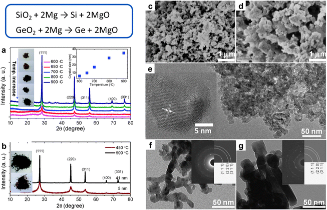 | ||
| Fig. 15 Si and Ge NCs synthesized in molten LiCl/KCl. (a and b) XRD patterns of Si and Ge NCs synthesized at different temperatures. The insets in (a) are the corresponding digital images of Si NCs powders and the evolution of crystal size with synthesis temperature. The inset in (b) is the digital images of the powders of the Ge NCs. (c and d) SEM images for Si NCs synthesized at 600 °C and 800 °C. (e) HRTEM images for Si NCs synthesized at 600 °C. (f and g) TEM images of Ge NCs synthesized at 450 °C and 500 °C. The insets are the corresponding electron diffraction patterns. (Reproduced from ref. 152 with permission from The Royal Society of Chemistry.) | ||
The process applied for Si NPs can be easily extended to the synthesis of Ge NPs. Due to the much weaker bonding strength, Ge NPs were obtained at a much lower temperature (450 °C). The color of the product changed from wine red to black as the crystal size increased from 5 nm to over 20 nm (Fig. 15b, f and g). This change indicates again the presence of a quantum confinement effect for the Ge NPs. Despite that the particles obtained are aggregated for both Si and Ge, they are in fact easily re-dispersible in aqueous media, thus enabling further modification of the surface characteristics. The SMS route is expected to provide a cheap and scalable access for Si and Ge nanostructures, which may open up large scale applications of group IV nanomaterials in fields, such as photovoltaics.152
| 2Mg + SiO2 → Si + 2MgO | (26) |
| Si + C → SiC | (27) |
Through monitoring the phase evolution by XRD, it was clear that the formation of Si occurred at a lower temperature around 550 °C, while SiC was observed only at higher temperatures (>650 °C). We attribute this minor difference to the fact that the Si has to react with the amorphous carbon, which is expected to be driven by non-crystalline species, in equilibrium with the crystals at higher temperatures.
The results further showed that the characteristics of the produced SiC not only depend on the synthesis temperature, but also on the types of carbon precursors. A high synthesis temperature facilitates growth in crystal size which makes the hexagonal form 2H–SiC more stable (Fig. 16a and b). On the contrary, small crystals (<5 nm) stabilize with the cubic structure (Fig. 16c), regardless of the different synthesis temperatures (650–1000 °C). This result suggests that small crystal size always favors a high symmetric structure (3C–SiC), while bigger crystals are less dominated by surface energy and thereby can minimize their structure differently, i.e. the phase diagram for SiC in the nanoscale region is size dependent.
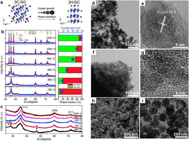 | ||
| Fig. 16 Phase and structure modulated synthesis of SiC in molten LiCl/KCl. (a) Schematic of phase transition driven by crystal growth for nanoscale SiC. (b) XRD patterns (left) of SiC synthesized from Mg, carbon and SiO2 at different temperatures. The right panel shows the dependence of phase fractions of cubic and hexagonal structure and crystal size on synthesis temperature. (c) XRD patterns of SiC synthesized from Mg, glucose and SiO2. Only cubic SiC is observed with very small crystal size (<5 nm). (d) TEM and (e) HETEM images of SiC NCs synthesized from Mg, carbon and SiO2 at 750 °C. (f) TEM and (g) HETEM images of SiC/C hybrid synthesized using glucose as carbon precursor. (h) SEM and (i) TEM of SiC nanospheres synthesized using silica nanospheres as templates. (Reprinted with permission from ref. 153. Copyright 2013 American Chemical Society.) | ||
Concerning morphology, the results indicate that the use of amorphous carbon always results in a particulate product composed of 8–40 nm crystallites depending on temperature (Fig. 16b, d and e). In contrast to that, the use of glucose as a carbon precursor led to SiC crystallites of much smaller size (<5 nm) dispersed in a carbon matrix (Fig. 16c, f and g). It is shown further that a templated synthesis in a salt melt could be realized by using silica microspheres of around 100–200 nm (Fig. 16h and i). These results clearly indicate that in the salt melt the control of phase as well as the microstructure for SiC is possible.153
5.3 B, C, N-based light element semiconductors
| NaBF4 + 3NaNH2 → h-BN + 4NaF + 3H2 + N2 | (28) |
The morphology of the products sensitively depends on the synthesis temperature. Conglomerates of NPs were obtained at 600 °C, while after increasing the temperature by another 100 °C, lamellar structures were observed, in line with the layered crystal structure of h-BN.
As h-BN is exactly isostructural and isoelectronic to graphite, and stimulated by the massive progress of graphene research, the development of a synthetic route to single or few layer BN sheet preparation also became particularly interesting for chemists. In a quite recent work, a molten salt process was shown to be very effective as a chemical oxidative exfoliation method to synthesise BN nanosheets from bulk h-BN.155 In the work reported by Li et al., bulk h-BN was treated in a molten NaOH/KOH at 180 °C within an autoclave, and afterwards the bulk powders were exfoliated into thin nanosheets via this reaction:
| BN + 3NaOH → Na3BO3 + NH3 | (29) |
The resultant products are mainly few layer nanosheets of larger than 100 × 100 nm in size. Mechanistically, the authors suggested that the process is based on a self-curling due to attached hydroxide anions and the following peeling off process. However, the yield of the process as given in the paper is only 0.2%, which implying majority of the bulk h-BN is etched away. Despite that there is still much space for the optimization of this process, this salt-melt based oxidative exfoliation process may potentially be applied for the synthesis of other inorganic two-dimensional (2D) materials from their bulk crystals (Fig. 17).
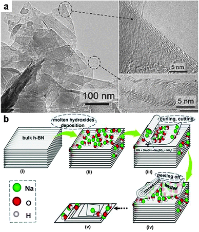 | ||
| Fig. 17 Exfoliation of bulk h-BN with molten hydroxides. (a) TEM images for the h-BN nanosheets exfoliated in NaOH/KOH melt at 180 °C. (b) Schematic illustration of the exfoliation mechanism based on a self-curling and peeling off process. (Reprinted with permission from ref. 155. Copyright 2013 John Wiley and Sons.) | ||
It is known that h-BN is a semiconductor (bandgap 5.2 eV) while graphite is a semimetal; alloying of BN and graphite could lead to stable compounds with narrower band gap than that of h-BN. This hybrid of BN and C could also be synthesized in a LiCl/KCl salt melt at 600–900 °C using NaBH4 as a boron precursor and urea or guanidine as nitrogen and carbon precursors. Through careful control of the synthesis conditions such as temperature and raw material ratio, water-dispersible h-BCN nanosheets and BCN NPs of around 5 nm size with varying carbon content were obtained. It was further shown that the BCN NPs are luminescent and that their emission spectra are adjustable by simply changing the carbon content, suggesting a possible composition-tuning of the bandgap in the ternary BCN system (Fig. 18).156
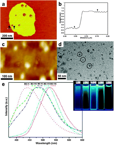 | ||
| Fig. 18 BCN nanostructure synthesized in LiCl/KCl with tunable bandgap. (a and b) Atomic force microscopy (AFM) characterization of the BCN nanosheets, (c) AFM and (d) TEM images of BCN NPs synthesized from NaBH4 and urea. (e) Photoluminescence spectra of the BCN dispersions synthesized under different conditions. (Reprinted with permission from ref. 156. Copyright 2011 American Chemical Society.) | ||
![[double bond, length as m-dash]](https://www.rsc.org/images/entities/char_e001.gif) NH)NHCN) was carried out in a LiCl/KCl melt at a temperature range of 380–600 °C,158 yielding uniform crystalline hexagonal nanoplates at over 580 °C (Fig. 19b and c). Based on both X-ray diffractometry and molecular modelling, the product derived from the salt melt route was assumed to be g-C3N4 which has a layered structure based on hexagonally arranged s-heptazine units (Fig. 19a–c). Since metal and chlorine are always present in the product, a lamellar structure with intercalated LiCl was suggested later by Wirnhier et al., based on thorough NMR and diffraction studies.159 This structural model, however, still seems incorrect. In a recent study, the poly-condensation of dicyandiamide was carried out in a LiBr/KBr, instead of LiCl/KCl. The resultant product was found to be 2D layers of poly(triazine imide) containing intercalated Br. This structure has still a 2D architecture but is completely different from that of either triazine or tri-s-triazine based layer arrangements suggested for g-C3N4. In addition, the stacking distance between two adjacent covalent layers can be adjusted through ion exchange of Br with F.160
NH)NHCN) was carried out in a LiCl/KCl melt at a temperature range of 380–600 °C,158 yielding uniform crystalline hexagonal nanoplates at over 580 °C (Fig. 19b and c). Based on both X-ray diffractometry and molecular modelling, the product derived from the salt melt route was assumed to be g-C3N4 which has a layered structure based on hexagonally arranged s-heptazine units (Fig. 19a–c). Since metal and chlorine are always present in the product, a lamellar structure with intercalated LiCl was suggested later by Wirnhier et al., based on thorough NMR and diffraction studies.159 This structural model, however, still seems incorrect. In a recent study, the poly-condensation of dicyandiamide was carried out in a LiBr/KBr, instead of LiCl/KCl. The resultant product was found to be 2D layers of poly(triazine imide) containing intercalated Br. This structure has still a 2D architecture but is completely different from that of either triazine or tri-s-triazine based layer arrangements suggested for g-C3N4. In addition, the stacking distance between two adjacent covalent layers can be adjusted through ion exchange of Br with F.160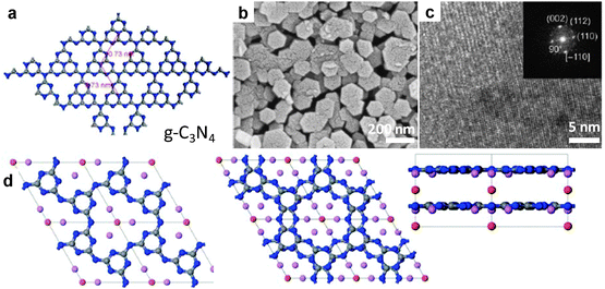 | ||
| Fig. 19 Polymeric carbon nitride semiconductor from SMS. (a) Proposed structure of the ideal single layer g-C3N4 based on 2D arranged s-heptazine (C6N7) units. (b) SEM and (c) TEM images of crystalline CN polymer synthesized in LiCl/KCl. (d) Proposed structure of the 2D poly(triazine imide) with intercalated Br synthesized in the salt melt of LiBr/KBr. Left: c-axis view of single layer; middle: c-axis view of two-layer stack, and right: b-axis view. Carbon, nitrogen, lithium and bromide atoms represented as grey, blue, purple and red spheres, respectively. (a–c, Reprinted with permission from ref. 158, d from ref. 160. Copyright 2008, 2013 John Wiley and Sons.) | ||
With regard to photocatalysis, it was until recently that the salt-derived crystalline triazineimide was found to be an efficient photocatalyst for hydrogen evolution from water.161 The activity was superior to that of the g-C3N4 obtained by simple condensation of precursors without salt. The enhanced performance was ascribed to the improved crystallinity for the products obtained by SMS as compared to that of direct condensation.
5.4 COFs and CTFs
Besides nanoscopic bulk materials, also porous materials can be synthesized in salt melts. Applications range from catalysis, gas storage and separation, energy conversion and storage to photonics. SMS allows constructing these porous materials from monomers or building blocks which already contain certain geometrical information in order to precisely control the properties of the final product. Such a polymerization, when carried out without solvent, on the one hand only proceeds incompletely because of restricted diffusion of the monomers which prohibits the formation of extended ordered structures.162 On the other, structures are dense, as pores cannot spontaneously form. Salt melts can act here both as high temperature solvent as well as porogen.Dynamic covalent chemistry (DCC) granted access to the synthesis of highly porous, crystalline, polymeric materials which are denoted as covalent organic frameworks (COF).163,164 This process relies on reversible reactions which allow for an inherent structure optimization during the formation as ordered materials with packing are thermodynamically more stable. Following the primary work of Yaghi and co-workers who reported on the synthesis of the first COF using boronic acids as precursors under standard solvothermal conditions (e.g. COF-1), so-called covalent triazine-based frameworks (CTFs) were only possible through the application of salt melt synthesis.165 Here, cheap and abundant aromatic nitriles as precursors were mixed with zinc chloride and heated in quartz ampules. Interestingly, ZnCl2 acts here as solvent for organic chemistry as it is capable of forming a homogeneous solution with the precursor molecules due to strong Lewis acid–base interactions. On the other hand, the salt melt also serves as a catalyst for the dynamic trimerization reaction and is therefore a highly suitable medium for the formation of extended, porous, high surface area frameworks which are thermally and chemically rather robust.
When 1,4-dicyanobenzene (DCB, Fig. 20a) was used as a precursor with one equivalent of ZnCl2, a crystalline triazine-based organic framework with sheet-like structure was obtained as revealed by XRD (CTF-1, Fig. 20b). Nitrogen sorption measurements revealed CTF-1 to possess a surface area of 791 m2 g−1 and a pore volume of 0.4 cm3 g−1 which closely resemble the values of COF-1. Additionally, the calculated pore size of 1.2 nm is in accordance with the theoretical model (Fig. 20c).165
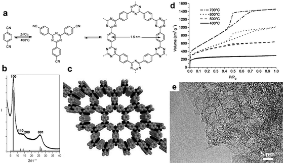 | ||
| Fig. 20 CTF-1 synthesized from DCB in molten ZnCl2. (a) Reaction scheme of the dynamic trimerization of terephthalonitrile in salt melt, leading to the formation of a 2D framework with 1.5 nm channels. (b) Observed powder XRD pattern of CTF-1 (black) and calculated powder XRD pattern from an optimized structure (eclipsed conformation AAA) of CTF-1 calculated with MS Modeling (gray). (c) Schematic representation of the structure of CTF-1 (C gray, N black); H atoms are omitted for clarity. (d) Nitrogen sorption isotherms of the poly-DCB prepared at different temperatures. (e) HR-TEM picture of the sample prepared at 700 °C. (a, b and e Reprinted with permission from ref. 165. Copyright 2008 American Chemical Society. c and d From 166, Copyright 2008 John Wiley and Sons.) | ||
SMS however does not only allow DCC, but also heating the covalent product beyond its stability limit. Here, an increase in temperature led to a strong increase of surface areas and pore volumes up to 3300 m2 g−1 and 2.4 cm3 g−1, respectively.166 This can be attributed to the occurrence of additional irreversible reactions of the triazine frameworks, i.e. a fragmentation–recombination mechanism which lowers the amount of nitrogen and creates additional mesoporosity by the onset of demixing with the salt phase. Eventually, this resulted in hierarchically structured micro- and mesoporous materials which are better described as nitrogen-rich carbonaceous polymer resins (Fig. 20e).
In a following study, Thomas and co-workers were able to synthesize mesoporous materials through the variation of salt amount and type of precursor, reaching pore sizes up to 20 nm in diameter.167 In this work, it was also shown, that the porosity is mainly governed by the degree of phase separation, i.e. the miscibility of the precursor with the salt. Following the example of CTF-1, Bojdys and co-workers employed the compound 2,6-naphthalenedicarbonitrile as precursor under the same reaction conditions.168 Based on the more rigid architecture and the relatively higher chemical stability, the introduction of mesopores could be achieved.
The chosen examples within this paragraph to our opinion nicely elucidate the potential of SMS, and also open the way to high temperature organic chemistry and its otherwise inaccessible reaction pathways. We believe that the SMS method can be expected to grow especially in this area of research, with high probability of leading to a set of very unexpected observations and reaction schemes.
6. Carbon nanostructures
6.1 Porous carbon by directed carbonization of sugar in non-reactive salt fluxes
Carbon is one of the most important materials which experienced a renaissance because of its diverse architectures with a specific nanostructure and is now pursued extensively for different applications. Porous carbon, for instance, can be either a catalyst support or a medium for storing energy electrochemically. Synthesis of porous carbon can be realized in various ways from different resources such as biomass, coal and polymerizable molecules. Chemical activation is still the standard technique to generate carbons with very high surface area, but comes with different disadvantages, such as materials defunctionalization and mass loss due to etching. We have recently converted glucose to porous carbons using the eutectic salt melt LiCl/KCl.169 In the salt melt, the carbonization of glucose proceeds gradually through the elimination of water. This process has been monitored by spectroscopic techniques, like XRD, FT-IR and Raman spectroscopy. The porosity of the carbonaceous product increases with carbonization temperature and reaches a maximum value near 600 m2 g−1 at 700 °C, but then decreases notably due to graphitization and improved sample stacking. The porosity is contributed largely by micropores (pore size < 2 nm). With respect to microstructure, the products have an irregular and hierarchical morphology (see Fig. 23 in the following section), and synthesis temperature exerts an obvious influence on the evolution of microstructures as can be seen from the EM images.The mechanism for formation of porosity in metal chloride melt is however unclear and potentially very exciting. Contrary to direct carbonization without salt which does not result in meaningful porosity, in the salt melt media glucose is carbonized from a solvated form. Several recent publications attribute a template role to the intentionally added salt during the synthesis of carbons and other inorganic materials.170,171 While in our opinion the formation of pores in our system can be of different origins which await to be revealed in further investigations.
Since the carbons derived from the salt at even 1000 °C showed high sp2-hybridization, but only little graphitic domains, it is quite natural to add transition metals which have been found to accelerate the graphitization of carbonaceous materials.172–174 Based on our results, we found that iron, regardless of its oxidation state and chemical form, is the most active catalyst for graphitization among the late 3-d transition metals examined. The addition of an iron salt to a molten salt solvent, as we expect, leads to completely miscible solvent. However, here we cannot exclude the presence of spurious amounts of iron (<10 ppm) or other transition metals in the original salt melt, as they are natural impurities in salt stocks. In the presence of intentionally added iron salts (FeCl2), the graphitization of glucose is obviously promoted, which is indicated by the increase in the peak intensities in XRD patterns (002 peak) and the Raman spectra (D peak). Moreover, the added iron salt catalyst also leads texturally to a remarkable increase in the fraction of sheet-like structures, which are ascribed to thin graphite stacks.169
6.2 Carbonization of ionic liquids in salt melts to ultrahigh surface area carbons with salts as molecular templates
As stated in Section 6.1, carbon belongs to a unique class of materials since its diverse properties render it highly suitable for many applications while still being economical and abundant. However, it is nowadays a commonly accepted approach that the properties of carbon materials can be improved through the introduction of heteroatoms such as nitrogen, boron, sulfur or phosphor, with nitrogen being the most frequent example. Here, the foreign atoms can be attached to the surface, which mainly influences the chemical properties, whereas the structural incorporation of the heteroatoms alters the physical properties of the carbons.175–178Just recently, ionic liquids were presented as versatile precursors for heteroatom-doped carbons, with a negligible vapor pressure obviating the need for special equipment while the liquid state enables for facile handling and processing.179–184 Here, the nature of the doping atom can be controlled via the nature of the ionic liquid and the heteroatom amount and binding state via the adjusting of carbonization temperature. These materials are commonly nonporous; however, for most applications porosity and high surface areas are essential. In this regard, we recently presented an approach we call “salt templating” in which salt melts are used as solvents and porogen in this process. As many ionic liquids as ionic carbon precursors are fully miscible with many salt mixtures, this approach enabled the one-step synthesis of highly porous heteroatom-doped carbons with specific surface areas up to 2000 m2 g−1 and higher.170,185 The synthesis strategy is based on the idea of carbonizing a thermally cross-linkable salt, i.e. the ionic liquid, in the presence of a salt melt which cannot be cross-linked but washed out with water after completion of the condensation reaction. As porogen salts, eutectic mixtures of ZnCl2 with LiCl (LiZ), NaCl (SZ) and KCl (PZ), respectively, were chosen, since their melting points are within the range of onset of the ionic liquid crosslinking, all compounds are miscible over a sufficient temperature range and the porogen salts are water-soluble.
The synthesis was performed with the ionic liquids 1-butyl-3-methyl-pyridinium dicyanamide (Bmp-dca), 1-ethyl-3-methyl-imidazolium dicyanamide (Emim-dca) and 1-ethyl-3-methyl-imidazolium tetracyanoborate (Emim-tcb) in order to obtain nitrogen- and nitrogen–boron dual-doped carbons. Depending on the porogen salt, heteroatom-doped carbons with varying morphology and porosity are recovered after simple washing with water (Fig. 21).
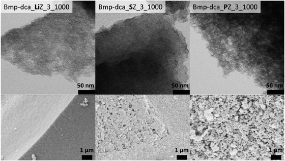 | ||
| Fig. 21 TEM (upper row) and SEM pictures (lower row) of nitrogen-doped carbons using Bmp-dca as precursor templated with LiZ (left), SZ (middle) and PZ (right) at equal mass ratios synthesized at 1000 °C. (Reprinted with permission from ref. 170. Copyright 2013 John Wiley and Sons.) | ||
The products derived from the salt melts possess significantly distinguished morphologies and porosities, reflecting the local structure of the different salt melts. This is nicely illustrated by the nitrogen sorption measurements of carbon materials which were synthesized with different ionic liquids but the same porogen salts, all revealing comparable porosities for the respective salt mixture (Fig. 22). Therefore, it is reasonable to ascribe a template character to the porogen salts where the pore size corresponds to salt clusters and their percolation structures resulting in micro- to mesoporous materials.
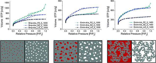 | ||
| Fig. 22 Upper row: nitrogen sorption isotherms of Bmp-dca (left), Emim-dca (middle) and Emim-tcb (right) derived carbons templated with LiZ, SZ and PZ at equal mass ratios. Lower row: schematic representation of pore formation for carbons templated with LiZ (left), SZ (middle) and PZ (right) at equal mass ratios. Each left image depictures the carbon (grey)–salt (red) composite and each left the carbon after washing. (Reprinted with permission from ref. 170. Copyright 2013 John Wiley and Sons.) | ||
Even the utilization of very high salt concentrations did not influence the carbon yield but led to very lightweight materials with pores of up to 12 nm in diameter and pore volumes of 2.75 cm3 g−1. Combining carbon synthesis with inorganic synthesis in salt melts, many different combinations of ionic liquids, porogen salts and metal compounds synthesized simultaneously in situ may be envisioned.
6.3 Converting glucose to graphene
As discussed in Section 6.1, glucose can be converted into carbon of primarily sp2 aromatic C–C bonds in salt melts at elevated temperatures. It was surprising that sheet-like structures were observed by EM for all samples prepared even at comparably low temperatures. The question if it is possible to produce sp2 carbons like nanotube or graphene in the salt melt in large quantity is a plausible deduction. Initial results indeed demonstrated that conversion of glucose in salt melt into graphenes with significantly improved purity is possible.169 As it was speculated that the solution process forms the graphene sheets, while a precipitation process results in only weakly ordered carbon, the carbonization of glucose was carried out at a much lower concentration (glucose/salt = 1/100, as compared to 1/10 for the normal process). Here, thin-layer structures are notably enriched across the sample (Fig. 23), suggesting that indeed a solution growth mechanism is involved. This is also reflected by a change in the nitrogen sorption isotherm which evolved from a high plateau shape (because of microporosity) to linear volume–pressure dependence due to the absence of porosity and sheet surface adsorption. Using AFM, the thin layer structures are directly confirmed to be few-layer graphenes with a thickness from 0.6 nm to 5 nm (Fig. 23e). However, apparent in-plane structure disorder is still present for the graphenes synthesized in salt melt as the electron diffraction measurement by TEM revealed only a diffuse ring structure (Fig. 23d).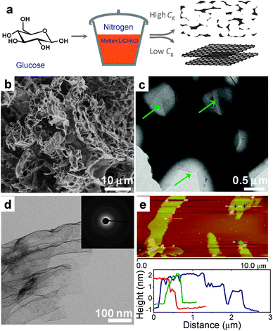 | ||
| Fig. 23 Graphene from glucose by SMS. (a) Schematic of conversion of glucose to porous carbon (or graphene) at high (or low) glucose concentration (Cg) in LiCl/KCl melt. (b) SEM and (c) TEM images of the porous carbon synthesized at 800 °C with high Cg (glucose/salt = 1/10). The green arrows in (c) point the thin-layer at the edge of the main structure. (d) TEM and (e) AFM images for the graphene synthesized from glucose at low Cg (glucose/salt = 1/100). (Reprinted with permission from ref. 169. Copyright 2013 John Wiley and Sons.) | ||
To enhance the efficiency of graphene production using the salt melt route, an iron catalyst is a good option, which was confirmed to improve graphitization. For the synthesis of high purity graphene, carbonization however still needs to be carried out at low precursor concentration, and the efficiency of this process is still steadily improved at present. Interestingly, the catalytically derived MS graphene becomes magnetic even after washing with HCl solution, implying the remaining iron atoms to be trapped at or intercalated in between the graphene layers.
6.4 Chemical structure control of carbon materials by metal chloride salts
Carbonaceous materials are classically activated in order to introduce porosity by different physical and chemical routes. Classical chemical activation is often performed with molten alkali metal hydroxides which are oxidizing and etch out weakly bonded carbon atoms at elevated temperatures (>500 °C).186 Pore generation in carbons can also be carried out in salt melts of ZnCl2, which look at a first glance as an activation effect comparable to KOH or NaOH. In an early study of Caturla et al.,187 peach stones were selected as the raw material and were treated with varying amounts of ZnCl2. The results revealed an increase in the surface area but reduction in yield with increasing amount of the ZnCl2. At the optimized condition, the surface area reached 2100 m2 g−1, and a bulk density of around 0.3 g cm−3 for a sample carbonized at only 500 °C was found. A similar salt melt dehydration process using ZnCl2 was applied later to several lignocellulosic materials such as coconut shells and olive stones, and the creation of porosity and surface area over 1000 m2 g−1 were reported. In some recent work on porous polymers as well as carbons produced from ZnCl2,153,188,189 the role of ZnCl2 being solely a chemical activation agent was questioned, and the authors claimed that different mechanisms are dominant. Such mechanisms regarding the pore generation using ZnCl2 have been proposed in some early works. In the first place, acidic chlorides like AlCl3 and ZnCl2 are generally regarded as “Friedel-Crafts”-type catalysts that favors the condensation (alkylation and acylation reactions) of aromatic hydrocarbons. Moreover, it is known that ZnCl2 for cellulosic materials serves as the dehydration agent, i.e. it removes H2O molecules from the backbone and therefore promotes the formation of reactive double bonds of the carbon skeleton, and by their cyclo-addition the creation of pores.190,191 On top of that and at higher temperatures, the reduction of ZnCl2 (possibly ZnO) should be considered in some cases. It is at least thermodynamically feasible that carbon reduces zinc compounds, which opens up the side path of an oxidative pore formation.6.5 Reactive doping and simultaneous generation of ultrahigh porosity by dissolved oxysalts
The carbonization of sugar described above is performed in inert chloride salts. In order to modify chemically the carbons using the salt melt, our group has performed the carbonization in the presence of reactive, oxidizing salts, such as nitrate and sulfate. As for nitrate, heating its mixture with glucose in even a nitrogen atmosphere could lead to explosion or drastic combustion, which is mechanistically the same as the combustion of black powder. When the mixture of glucose and nitrate (LiNO3 in our work) is diluted with a LiCl–KCl melt, runaway combustion does not occur, allowing capturing the carbon product in a usual way. The samples were synthesized at different temperatures and different nitrate/glucose ratios.192 We found that the increase in either nitrate/glucose ratio or reaction temperature let to the decrease in product yield, implying continued oxidation of carbon by nitrate in the melt. The samples showed remarkable changes in characteristics as compared to the products obtained in only chlorides melt without nitrate. All the samples obtained showed very high specific surface areas. For instance, at 800 °C, the specific surface area reaches 1800 m2 g−1 (Fig. 21g), as compared to only around 200 m2 g−1 for samples from pure LiCl/KCl. Interestingly, the samples in different salt systems all evolved to a thin platelet morphology; that means the structure is presumably graphitic (Fig. 24b–d). After systematic analysis of the products, it was surprising to observe that all the samples contained significant amounts of nitrogen, which decreased from 13 wt% (600 °C) to 2% (1000 °C). After incorporation of nitrogen in the carbon, the (002) peak in the XRD pattern grows notably, which is common for N-doped carbon and indicates extended aromatization promoted by nucleophilic nitrogen-species. Using X-ray photoelectron spectroscopy (XPS), the presence of different C–N bonds was confirmed, in which N can be pyridinic, pyrrolic or graphitic (Fig. 24e). This result demonstrates clearly that N at its highest oxidation state of +5 in NO3− was reduced to −3 nitrogen atoms bonded to the sp2 carbons.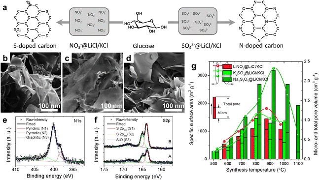 | ||
| Fig. 24 Synthesis of heteroatom doped carbon sheet in reactive molten salt. (a) Schematic of the formation of N and S-doped carbons from glucose in the salt system of NO3−@LiCl/KCl and SO42−@LiCl/KCl. (b–d) SEM images of doped carbon sheets synthesized in the salt systems of LiNO3@LiCl/KCl, K2SO4@LiCl/KCl and Na2S2O3@LiCl/KCl. (e and f) Fine scanned X-ray photoelectron spectra (XPS) in N 1s region for N-doped carbon produced in LiNO3@LiCl/KCl, and S 2p region for S-doped carbons produced in A: K2 SO42−@LiCl/KCl, B: Na2S2O3@LiCl/KCl. (g) Dependence of specific surface area and pore volumes on the synthesis temperature for the doped carbons derived from different salt systems. (Reprinted with permission from ref. 192. Copyright 2013 John Wiley and Sons.) | ||
Stimulated by the successful N doping from nitrate, the process was extended for the doping of sulfur into carbon by simply replacing nitrate with a sulfate (K2SO4). Indeed sulfur doping can be realized similarly in this manner. Elemental analysis revealed sulfur contents up to 16 wt% for samples prepared at 600 °C. With the increase in synthesis temperature, the sulfur concentration decreased rapidly to only 2–3 wt% at over 1000 °C; this is typical for S-doped carbons as the C–S bonds are energetically weaker compared to C–C bonds. Based on the XPS results, sulfur atoms are bonded to the sp2 carbon network in the primarily reduced (sulfide) form, together with a small amount of oxidized sulfur (S–O bonds). Similar to the previous systems, the surface area for the sulfur doped carbon prepared in this process also shows notable increase, suggesting an activation mechanism for both of the nitrate and sulfate anions. To achieve higher S-content, we replaced sulfate with thiosulfate, which contained S in the oxidation state of −2 and +6. Maximum S-content up to 30 wt% was observed for the sample obtained at 600 °C, also in the form of primarily thiophone-S and a small amount of oxidized sulfones. Surprisingly, the surface area of S-doped carbon synthesised in the presence of Na2S2O3 exceeds 3200 m2 g−1, which is larger than the theoretical value for completely exfoliated graphene, and comparable to finely activated carbons.
The origin of the activation process can be understood by considering simple thermodynamics between carbon and the oxoanions. For instance, assuming that CO2 is the oxidation product, the reaction of carbon with nitrate can be expressed as:
| 5C + 4NO3− → 5CO2 + 2N2 + 2O2− | (30) |
While the reaction of the sulfate anion with carbon occurs in a different way as it is not as oxidizing as nitrate:
| C + 2SO42− → CO2 + 2SO2 + 2O2− | (31) |
The above reactions explain the formation of porosity and the decrease in yield with temperature, which is due to oxidative etching out of carbon atoms. The question of when and how the dopant atoms (N or S) bond to the sp2 carbon remains unclear. Mechanistic investigations in this direction are still in progress, but have some relevance for all possible organic chemistry in salt melts.
6.6 Carbon nanotubes and graphite/salt intercalation compounds
In this last section of salt melt carbon synthesis, we select two more examples which could promise broader application of the SMS route. The first example is the synthesis of carbon nanotubes (CNT). CNTs have indeed been synthesized in molten salts, electrochemically. By electrolysis of a graphite electrode in alkali metal chlorides (LiCl and KCl), it was observed that the solid graphite becomes disintegrated and scrolls-up to CNTs (Fig. 25).193–196 The product of this process can be easily collected from the salt melt and the efficiency of the synthesis is rather high compared to other CNT synthesis routes, such as chemical vapour deposition (CVD).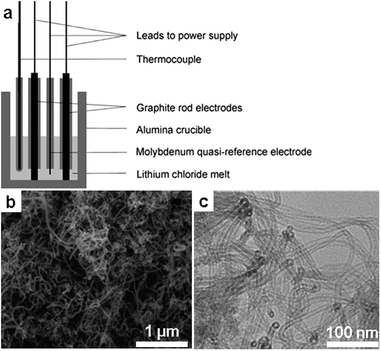 | ||
| Fig. 25 CNT production in molten chloride. (a) Schematic of the cell design for the electrolysis of graphite for CNT production. (b) SEM and (c) TEM images of CNTs produced in molten salt. (Reprinted with permission from ref. 196. Copyright 2012 Elsevier.) | ||
In the second example, graphite intercalation compounds were formed by reacting graphite with salt. This is in fact simple, well known intercalation chemistry between graphite and FeCl3, which is constructed from stacking layers of 2D FeCl6 octahedrons (Fig. 26). Reaction of graphite with FeCl3 results in a crystal in which carbon sp2 layer(s) are sandwiched periodically in between the 2D FeCl6 octahedrons. In addition, such intercalation compounds can have various structures depending on the sequence of stacking between graphene and FeCl3 layers. Up to now, graphite intercalation compounds with FeCl3 of different c-axis length have been reported.197–201
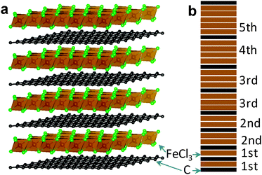 | ||
| Fig. 26 Graphite/FeCl3 intercalation compound. (a) Structure of a 1st stage FeCl3/graphite intercalation compound. (b) Schematic illustration of FeCl3/graphite intercalate from 1st to 5th stage. | ||
7. Conclusions and future directions
After almost 50 years of development, the process of SMS has spread from the initial oxide ceramics to a wide range of nanomaterials, including polymer processes and carbon synthesis. As a high temperature ionic solvent, the strong polarizing nature at high temperatures offers unparalleled solvation power for oxides and covalent solids, and therefore facilitates mass transport and nucleation processes in a continuous liquid phase. We have reviewed here recent progress of SMS in inorganic crystalline materials, including oxide, non-oxide, semiconductors and carbon nanostructure. The SMS route is, in our opinion, especially suited for the production of materials which have traditionally suffered by slow crystallization kinetics in conventional wet-chemistry routes. As shown here, all metal borides, silicon and SiC which are all built up from strong covalent bonds could be easily accessed with highly crystalline character. The process also improves the crystallization of carbon nitride, and even carbon itself can be crystallized to 2D layered structures, however being presumably polycrystalline in the planes.Another big advantage lies in the potential of morphosynthesis of controlled nanostructures by SMS, where – again due to the highly polar character of this special solvent – rather unusual highly polar faces of the NCs are getting exposed, which are otherwise hard to access. These faces are in many cases also the most interesting ones, as they for instance allow unusual catalytic activations or oriented attachment towards delicate superstructures.
For a fundamental chemical insight into the materials synthesis by SMS, there is however still much to be revealed, as the process and the chemistry behind are quite different from conventional wet-chemistry approaches. For instance, on a molecular level the structure of ionic salt species in many systems has not yet been unambiguously understood, let alone the interaction of the salt cations and anions with many dissolved reactants, the solvation thermodynamics and the (colloidal) process of nucleation and growth and stabilization in salt melts. Investigations towards these directions are usually more complicated, as the high reaction temperature impedes the use of in situ structural characterization techniques.
On the other hand, the SMS route certainly opens up many, partly radically new possibilities for the synthesis of known materials but also new material development, as illustrated in many cases in this review. This route may also be a non-topochemical approach for the oxidative delamination of layered materials, as demonstrated for BN nanosheets. We further believe this route may also offer new, still not accessed possibilities to build new complex structures, such as new zeolitic materials, metal organic frameworks, and polymer chemistry by utilizing tailored salt systems.
As a final comment, SMS can usually be regarded as a quite green process because many salts are not volatile or harmful, and they are mostly environmentally benign and can be easily recycled. Industrialization of this process therefore seems attractive. Magnified lab-scale batch synthesis can be a plausible route, which is simple and straightforward, but usually has low efficiency in terms of energy and time. For large scale synthesis, we may adopt a similar continuous melting method applied in the glass industry, which is much more energy-efficient and capable of large scale production. However, to realize such a system for SMS, substantial technical obstacles need to be overcome, such as the separation of products from salt melt and the integration of salt recycling into the whole systems.
Acknowledgements
The authors acknowledge the financial support from the Max-Planck Society. M.A. thanks the ERC for an Advanced Grant enabling unconventional experiments. X.L. thanks the Alexander von Humboldt foundation for providing the fellowship.Notes and references
- K. S. Novoselov, A. K. Geim, S. V. Morozov, D. Jiang, Y. Zhang, S. V. Dubonos, I. V. Grigorieva and A. A. Firsov, Science, 2004, 306, 666–669 CrossRef CAS.
- K. S. Novoselov, D. Jiang, F. Schedin, T. J. Booth, V. V. Khotkevich, S. V. Morozov and A. K. Geim, Proc. Natl. Acad. Sci. U. S. A., 2005, 102, 10451–10453 CrossRef CAS.
- C. B. Murray, D. J. Norris and M. G. Bawendi, J. Am. Chem. Soc., 1993, 115, 8706–8715 CrossRef CAS.
- X. G. Peng, L. Manna, W. D. Yang, J. Wickham, E. Scher, A. Kadavanich and A. P. Alivisatos, Nature, 2000, 404, 59–61 CrossRef CAS.
- C. B. Murray, C. R. Kagan and M. G. Bawendi, Annu. Rev. Mater. Sci., 2000, 30, 545–610 CrossRef CAS.
- B. L. Cushing, V. L. Kolesnichenko and C. J. O'Connor, Chem. Rev., 2004, 104, 3893–3946 CrossRef CAS.
- Y. Yin and A. P. Alivisatos, Nature, 2005, 437, 664–670 CrossRef CAS.
- J. Park, J. Joo, S. G. Kwon, Y. Jang and T. Hyeon, Angew. Chem., Int. Ed., 2007, 46, 4630–4660 CrossRef CAS.
- J. R. Heath and J. J. Shiang, Chem. Soc. Rev., 1998, 27, 65–71 RSC.
- D. E. Bugaris and H. C. zur Loye, Angew. Chem., Int. Ed., 2012, 51, 3780–3811 CrossRef CAS and references therein.
- M. G. Kanatzidis, R. Pöttgen and W. Jeitschko, Angew. Chem., Int. Ed., 2005, 44, 6996–7023 CrossRef CAS.
- W. Sundermeyer, Angew. Chem., Int. Ed., 1965, 4, 222–238 CrossRef.
- S. V. Volkov, Chem. Soc. Rev., 1990, 19, 21–28 RSC.
- D. H. Kerridge, Pure Appl. Chem., 1975, 41, 355–371 CrossRef CAS.
- J. L. Sudworth, J. Power Sources, 2001, 100, 149–163 CrossRef CAS.
- S. Giddey, S. P. S. Badwal, A. Kulkarni and C. Munnings, Prog. Energy Combust. Sci., 2012, 38, 360–399 CrossRef CAS.
- D. Inman and S. H. White, J. Appl. Electrochem., 1978, 8, 375–390 CrossRef CAS.
- G. Z. Chen, D. J. Fray and T. W. Farthing, Nature, 2000, 407, 361 CrossRef CAS.
- T. Nohira, K. Yasuda and Y. Ito, Nat. Mater., 2003, 2, 397–401 CrossRef CAS.
- M. Antonietti, D. Kuang, B. Smarsly and Y. Zhou, Angew. Chem., Int. Ed., 2004, 43, 4988–4992 CrossRef CAS.
- Z. Ma, J. Yu and S. Dai, Adv. Mater., 2010, 22, 261–285 CrossRef CAS.
- N. H. Nachtrieb, Annu. Rev. Phys. Chem., 1980, 31, 131–156 CrossRef CAS.
- E. C. Honea, M. L. Homer, P. Labastie and R. L. Whetten, Phys. Rev. Lett., 1989, 63, 394–397 CrossRef CAS.
- A. Selloni, P. Carnevali, R. Car and M. Parrinello, Phys. Rev. Lett., 1987, 59, 823–826 CrossRef CAS.
- H. Lux, Z. Elektrochem., 1939, 45, 303–309 CAS.
- H. Flood and T. Förland, Acta Chem. Scand., 1947, 1, 592–604 CrossRef CAS.
- A. Stein, S. W. Keller and T. E. Mallouk, Science, 1993, 259, 1558–1564 CAS.
- D. P. Shoemaker, D. Y. Chung, J. F. Mitchell, T. H. Bray, L. Soderholm, P. J. Chupas and M. G. Kanatzidis, J. Am. Chem. Soc., 2012, 134, 9456–9463 CrossRef CAS.
- L. H. Zhu and Q. W. Huang, Ceram. Int., 2011, 37, 249–255 CrossRef CAS.
- L. H. Zhu, Q. W. Huang and W. Liu, Ceram. Int., 2008, 34, 1729–1733 CrossRef CAS.
- H. I. Hsiang, T. H. Chen and C. C. Chuang, J. Am. Ceram. Soc., 2007, 90, 4070–4072 CAS.
- Y. Du and D. Inman, J. Mater. Chem., 1996, 6, 1239–1240 RSC.
- D. H. Kerridge and W. M. Shakir, Thermochim. Acta, 1991, 182, 107–122 CrossRef CAS.
- X. Jin and L. Gao, J. Am. Ceram. Soc., 2004, 87, 533–540 CrossRef CAS.
- L. H. Zhu and Q. W. Huang, Ceram. Int., 2011, 37, 249–255 CrossRef CAS.
- H. I. Hsiang, T. H. Chen and C. C. Chuang, J. Am. Ceram. Soc., 2007, 90, 4070–4072 CAS.
- D. H. Kerridge and W. M. Shakir, Thermochim. Acta, 1988, 136, 149–152 CrossRef CAS.
- Z. P. Guo, G. D. Du, Y. Nuli, M. F. Hassan and H. K. Liu, J. Mater. Chem., 2009, 19, 3253–3257 RSC.
- Y. Wang and J. Y. Lee, J. Phys. Chem. B, 2004, 108, 17832–17837 CrossRef CAS.
- C. Xu, X. Zhao, S. Liu and G. Wang, Solid State Commun., 2003, 125, 301–304 CrossRef CAS.
- X. Wang, X. Han, S. Xie, Q. Kuang, Y. Jiang, S. Zhang, X. Mu, G. Chen, Z. Xie and L. Zheng, Chem.–Eur. J., 2012, 18, 2283–2289 CrossRef CAS.
- D. H. Kerridge and J. C. Rey, J. Inorg. Nucl. Chem., 1975, 37, 2257–2260 CrossRef CAS.
- M. Raciulete, A. Kachina, E. Puzenat and P. Afanasiev, J. Solid State Chem., 2010, 183, 2438–2444 CrossRef CAS.
- B. Roy, S. P. Ahrenkiel and P. A. Fuierer, J. Am. Ceram. Soc., 2008, 91, 2455–2463 CrossRef CAS.
- P. Afanasiev, J. Phys. Chem. C, 2012, 116, 2371–2381 CAS.
- Z. Y. Jiang, T. Xu, Z. X. Xie, Z. W. Lin, X. Zhou, X. Xu, R. B. Huang and L. S. Zheng, J. Phys. Chem. B, 2005, 109, 23269–23273 CrossRef CAS.
- P. Afanasiev and C. Geantet, Coord. Chem. Rev., 1998, 178–180, 1725–1752 CrossRef CAS.
- N. B. Singh, Prog. Cryst. Growth Charact., 2002, 44, 183–188 CrossRef CAS.
- D. A. Habboush and D. H. Kerridge, Thermochim. Acta, 1981, 44, 151–156 CrossRef CAS.
- N. B. Singh and D. H. Kerridge, Thermochim. Acta, 1983, 67, 147–156 CrossRef CAS.
- D. H. Kerridge and J. C. Rey, J. Inorg. Nucl. Chem., 1975, 37, 2257 CrossRef CAS.
- R. I. Dearnaley, D. H. Kerridge and D. J. Rogers, Inorg. Chem., 1985, 24, 4254–4258 CrossRef CAS.
- D. A. Habboush, D. H. Kerridge and S. A. Tariq, Thermochim. Acta, 1983, 65, 53–60 CrossRef CAS.
- Y. Du and D. Inman, J. Mater. Sci., 1997, 32, 2373–2379 CrossRef CAS.
- T. J. Park and S. S. Wong, Chem. Mater., 2006, 18, 5289–5295 CrossRef CAS.
- Y. Zhan, C. Yin, C. Zheng, W. Wang and G. Wang, J. Solid State Chem., 2004, 177, 2281–2284 CrossRef CAS.
- P. D. Hooker and K. J. Klabunde, Chem. Mater., 1993, 5, 1089–1093 CrossRef CAS.
- T. Xu, X. Zhou, Z. Jiang, Q. Kuang, Z. Xie and L. Zheng, Cryst. Growth Des., 2009, 9, 192–196 CAS.
- X. Wang, C. Hu, H. Liu, G. Du, X. He and Y. Xia, Sens. Actuators, B, 2012, 144, 220–225 CrossRef.
- Q. Sun, Y. Zeng and D. Jiang, Appl. Phys. Lett., 2012, 101, 073109 CrossRef.
- Y. Mao, T. Tran, X. Guo, J. Y. Huang, C. K. Shih, K. L. Wang and J. P. Chang, Adv. Funct. Mater., 2009, 19, 748–754 CrossRef CAS.
- Z. Zhang, C. Hu, Y. Xiong, R. Yang and Z. L. Wang, Nanotechnology, 2007, 18, 465504 CrossRef.
- P. Afanasiev, C. Geantet, M. Lacroix and M. Breysse, J. Catal., 1996, 162, 143–146 CrossRef CAS.
- C. Hu, H. Liu, W. Dong, Y. Zhang, G. Bao, C. Lao and Z. L. Wang, Adv. Mater., 2007, 19, 470–474 CrossRef CAS.
- D. Hudry, A. Rakhmatullin, C. Bessada, I. Bardez, F. Bart, S. Jobic and P. Deniard, Inorg. Chem., 2009, 48, 7141–7150 CrossRef CAS.
- V. A. Volkovich, T. R. Griffiths and R. C. Thied, Phys. Chem. Chem. Phys., 2003, 5, 3053–3060 RSC.
- P. Afanasiev, Chem. Mater., 1999, 11, 1999–2007 CrossRef CAS.
- J. R. Van Wazer and K. A. Holst, J. Am. Chem. Soc., 1950, 72, 639–644 CrossRef CAS.
- J. R. Van Wazer and D. A. Campanella, J. Am. Chem. Soc., 1950, 72, 655–663 CrossRef CAS.
- J. R. Van Wazer, Phosphorus and Its Compounds. Vol. 1 Chemistry, Interscience, New York, 1958 Search PubMed.
- J. R. Van Wazer and C. F. Calliss, Chem. Rev., 1958, 58, 1011–1046 CrossRef CAS.
- J. Nakano, S. Miyazawa and T. Yamada, Mater. Res. Bull., 1979, 14, 21–26 CrossRef CAS.
- M. Anghelov and B. M. Wanklyn, J. Mater. Sci. Lett., 1986, 5, 1067–1069 CrossRef.
- J. Nakano, T. Yamada and S. Miyazawa, J. Cryst. Growth, 1979, 47, 693–698 CrossRef CAS.
- H. J. Koo and M. H. Whangbo, Inorg. Chem., 2002, 41, 4664–4672 CrossRef CAS.
- H. Liu, C. Hu and Z. L. Wang, Nano Lett., 2006, 6, 1535–1540 CrossRef CAS.
- Y. Mao, S. Banerjee and S. S. Wong, J. Am. Chem. Soc., 2003, 125, 15718–15719 CrossRef CAS.
- Y. Mao and S. S. Wong, Adv. Mater., 2005, 17, 2194–2199 CrossRef CAS.
- H. Deng, Y. Qiu and S. Yang, J. Mater. Chem., 2009, 19, 976–982 RSC.
- P. M. Rørvik, T. Lyngdal, R. Saterli, A. T. J. van Helvoort, R. Holmestad, T. Grande and M. A. Einarsrud, Inorg. Chem., 2008, 47, 3173–3181 CrossRef.
- K. S. Tan, M. V. Reddy, G. V. Subba Rao and B. V. R. Chowdari, J. Power Sources, 2005, 147, 241–248 CrossRef CAS.
- C.-H. Han, Y.-S. Hong, C. M. Park and K. Kim, J. Power Sources, 2001, 92, 95–101 CrossRef CAS.
- H. Chen and C. P. Grey, Adv. Mater., 2008, 20, 2206–2210 CrossRef CAS.
- J. H. Kim, S. T. Myung and Y. K. Sun, Electrochim. Acta, 2004, 49, 219–227 CrossRef CAS.
- X. Yang, W. Tang, H. Kanoh and K. Ooi, J. Mater. Chem., 1999, 9, 2683–2690 RSC.
- M. Helan, L. J. Berchmans, T. P. Jose, A. Visuvasam and S. Angappan, Mater. Chem. Phys., 2010, 124, 439–442 CrossRef CAS.
- Z. Chang, Z. Chen, F. Wu, X. Z. Yuan and H. Wang, Electrochim. Acta, 2009, 54, 6529–6535 CrossRef CAS.
- J. F. Ni, H. H. Zhou, J. T. Chen and X. X. Zhang, Mater. Lett., 2007, 61, 1260–1264 CrossRef CAS.
- G. T. K. Fey, Y. C. Lin and H. M. Kao, Electrochim. Acta, 2012, 80, 41–49 CrossRef CAS.
- M. M. Rahman, J. Z. Wang, M. Faiz Hassan, S. Chou, D. Wexler and H. K. Liu, J. Power Sources, 2010, 195, 4297–4303 CrossRef CAS.
- L. Cheng, H. J. Liu, J. J. Zhang, H. M. Xiong and Y. Y. Xia, J. Electrochem. Soc., 2006, 153, A1472–A1477 CrossRef CAS.
- T. Kojima, A. Kojima, T. Miyuki, Y. Okuyama and T. Sakai, J. Electrochem. Soc., 2011, 158, A1340–A1346 CrossRef CAS.
- C. Matei, D. Berger, P. Marote, S. Stoleriu and J. P. Deloume, Prog. Solid State Chem., 2007, 35, 203–209 CrossRef CAS.
- T. Kojima, K. Nomura, Y. Miyazaki and K. Tanimoto, J. Am. Ceram. Soc., 2006, 89, 3610–3616 CrossRef CAS.
- J. Yang, R. Li, J. Zhou, X. Li, Y. Zhang, Y. Long and Y. Li, J. Alloys Compd., 2010, 508, 301–308 CrossRef CAS.
- K. H. Yoon, Y. S. Cho and D. H. Kang, J. Mater. Sci., 1998, 33, 2977–2984 CrossRef CAS.
- C. C. Chiu, C. C. Li and S. B. Desu, J. Am. Ceram. Soc., 1991, 74, 38–41 CrossRef CAS.
- W. Meng and A. V. Virkar, J. Solid State Chem., 1999, 148, 492–498 CrossRef CAS.
- C. Shivakumara, Solid State Commun., 2006, 139, 165–169 CrossRef CAS.
- R. H. Arendt, J. Solid State Chem., 1973, 8, 339–347 CrossRef CAS.
- D. G. Porob and P. A. Maggard, J. Solid State Chem., 2006, 179, 1727–1732 CrossRef CAS.
- J. Sun, G. Chen, Y. Li, R. Jin, Q. Wang and J. Pei, Energy Environ. Sci., 2011, 4, 4052–4060 CAS.
- C. Y. Xu, L. Zhen, R. Yang and Z. L. Wang, J. Am. Chem. Soc., 2007, 129, 15444–15445 CrossRef CAS.
- D. B. Hedden, C. C. Torard and W. Zegarski, J. Solid State Chem., 1995, 118, 419–421 CrossRef CAS.
- P. Afanasiev, Mater. Lett., 2007, 61, 4622–4626 CrossRef CAS.
- L. Fuoco, D. Rodriguez, T. Peppel and P. A. Maggard, Chem. Mater., 2011, 23, 5409–5414 CrossRef CAS.
- G. Photiadis, A. Maries, M. Tyrer, D. Inman, J. Bensted, S. Simons and P. Barnes, Adv. Appl. Ceram., 2011, 110, 137–141 CAS.
- H. Wada, K. Sakane, T. Kitamura, H. Hata and H. Kambara, J. Mater. Sci. Lett., 1991, 10, 1076–1077 CrossRef CAS.
- D. Gopi, J. Indira, L. Kavitha, S. Kannan and J. M. F. Ferreira, Spectrochim. Acta, Part A, 2010, 77, 545–547 CrossRef CAS.
- S. Jalota, A. C. Tas and S. B. Bhaduri, J. Mater. Res., 2004, 19, 1876–1881 CrossRef CAS.
- A. C. Tas, J. Am. Ceram. Soc., 2001, 84, 295–300 CrossRef CAS.
- S. Hashimoto and A. Yamaguchi, J. Eur. Ceram. Soc., 2000, 20, 397–402 CrossRef CAS.
- S. Hashimoto and A. Yamaguchi, J. Ceram. Soc. Jpn., 2004, 112, 104–109 CrossRef CAS.
- P. Zhang, J. Liu, H. Du, Z. Li, S. Li, S. Li and R. Xu, J. Alloys Compd., 2010, 491, 447–451 CrossRef CAS.
- P. Zhang, J. Liu, H. Du, Z. Li, S. Li and C. Chen, J. Alloys Compd., 2009, 484, 580–584 CrossRef CAS.
- P. Zhang, J. Liu, H. Du, S. Li, S. Li and R. Xu, Chem. Commun., 2010, 46, 3988–3990 RSC.
- M. Park, C. L. Choi, W. T. Lim, M. C. Kim, J. Choi and N. H. Heo, Microporous Mesoporous Mater., 2000, 37, 81–89 CrossRef CAS.
- M. Park, C. L. Choi, W. T. Lim, M. C. Kim, J. Choi and N. H. Heo, Microporous Mesoporous Mater., 2000, 37, 91–98 CrossRef CAS.
- C. L. Choi, M. Park, D. H. Lee, S. Komarneni and Y. H. Kim, J. Porous Mater., 2007, 14, 37–42 CrossRef CAS.
- C. L. Choi, M. Park, D. H. Lee, J. E. Kim, B. Y. Park and J. Choi, Environ. Sci. Technol., 2001, 35, 2812–2816 CrossRef CAS.
- J. Ma, Y. Gu, L. Shi, L. Chen, Z. Yang and Y. Qian, Chem. Phys. Lett., 2003, 381, 194–198 CrossRef CAS.
- D. Portehault, S. Devi, P. Beaunier, C. Gervais, C. Giordano, C. Sanchez and M. Antonietti, Angew. Chem., Int. Ed., 2011, 50, 3262–3265 CrossRef CAS.
- K. Amalajyothi, L. J. Berchmans, S. Angappan and A. Visuvasam, J. Cryst. Growth, 2008, 310, 3376–3379 CrossRef CAS.
- R. Yang, F. Luo and R. Xu, Mater. Trans., 2011, 52, 124–126 CrossRef CAS.
- X. Li, A. Westwood, A. Brown, R. Brydson and B. Rand, Carbon, 2009, 47, 201–208 CrossRef CAS.
- W. B. Tian, P. L. Wang, Y. M. Kann and G. J. Zhang, J. Alloys Compd., 2008, 461, L5–L10 CrossRef CAS.
- H. P. Martin, R. Ecke and E. Muller, J. Eur. Ceram. Soc., 1998, 18, 1737–1742 CrossRef CAS.
- X. Chen, Y. Li, Y. Li, J. Zhu, S. Jin, L. Zhao, Z. Lei and X. Hong, Ceram. Int., 2008, 34, 1253–1259 CrossRef CAS.
- H. H. Nersisyan, J. H. Lee and C. W. Won, Mater. Res. Bull., 2003, 38, 1135–1146 CrossRef CAS.
- H. H. Nersisyan, J. H. Lee and C. W. Won, Mater. Lett., 2005, 59, 3950–3954 CrossRef CAS.
- J. Ma, Y. Gu, L. Shi, L. Chen, Z. Yang and Y. Qian, J. Alloys Compd., 2004, 370, 281–284 CrossRef CAS.
- Z. Yang, Y. Gu, L. Chen, L. Shi, J. Ma and Y. Qian, Solid State Commun., 2004, 130, 347–351 CrossRef CAS.
- K. V. Manukyan, S. V. Aydinyan, K. G. Kirakosyan, S. L. Kharatyan, G. Blugan, U. Müller and J. Kuebler, Chem. Eng. J., 2008, 143, 331–336 CrossRef CAS.
- P. Afanasiev, L. Rawas and M. Vrinat, Mater. Chem. Phys., 2002, 73, 295–300 CrossRef CAS.
- M. G. Kanatzidis, Chem. Mater., 1990, 2, 353–363 CrossRef CAS.
- A. C. Sutorik and M. G. Kanatzidis, Chem. Mater., 1997, 9, 387–398 CrossRef CAS.
- T. H. Okabe and D. R. Sadoway, J. Mater. Res., 1998, 13, 3372–3377 CrossRef CAS.
- M. Baba, Y. Ono and R. O. Suzuki, J. Phys. Chem. Solids, 2005, 66, 466–470 CrossRef CAS.
- H. Zhao, S. Yang, H. You, Y. Wu and B. Ding, Green Chem., 2012, 14, 3197–3203 RSC.
- H. Zhao, C. Yu, H. You, S. Yang, Y. Guo, B. Ding and X. Song, J. Mater. Chem., 2012, 22, 4780–4789 RSC.
- J. Zhang, Cryst. Res. Technol., 2011, 46, 1058–1064 CrossRef CAS.
- C. Hu, Y. Xi, H. Liu and Z. L. Wang, J. Mater. Chem., 2009, 19, 858–868 RSC.
- W. S. Sheldrick and M. Wachhold, Angew. Chem., Int. Ed. Engl., 1997, 36, 207–224 CrossRef.
- C. Hu, W. Yan, B. Wan, K. Zhang, Y. Zhang and Y. Tian, Physica E, 2010, 42, 1790–1794 CrossRef CAS.
- B. Wan, C. Hu, H. Liu, Y. Xiong, F. Li, Y. Xi and X. He, Mater. Res. Bull., 2009, 44, 1846–1849 CrossRef CAS.
- B. Wan, C. Hu, B. Feng, Y. Xi and X. He, Mater. Sci. Eng., B, 2009, 163, 57–61 CrossRef CAS.
- Y. Zhang, C. Hu, C. Zheng, Y. Xi and B. Wan, J. Phys. Chem. C, 2010, 114, 14849–14853 CAS.
- H. Zhang, C. Hu, X. Wang, Y. Xi and X. Li, J. Alloys Compd., 2012, 513, 1–5 CrossRef CAS.
- D. Xiang, Y. Zhu, C. Cai, Z. He, Z. Liu, D. Yin and J. Luo, Physica E, 2011, 44, 733–737 CrossRef CAS.
- Y. Xi, C. Hu, X. Zhang, Y. Zhang and Z. L. Wang, Solid State Commun., 2009, 149, 1894–1896 CrossRef CAS.
- X. Li, C. Hu, X. Wang and Y. Xi, Appl. Surf. Sci., 2012, 258, 4370–4376 CrossRef CAS.
- X. Liu, C. Giordano and M. Antonietti, J. Mater. Chem., 2012, 22, 5454–5459 RSC.
- X. Liu, C. Giordano and M. Antonietti, Chem. Mater., 2013, 25, 2021–2027 CrossRef CAS.
- Y. Gu, M. Zheng, Y. Liu and Z. Xu, J. Am. Ceram. Soc., 2007, 90, 1589–1591 CrossRef CAS.
- X. Li, X. Hao, M. Zhao, Y. Wu, J. Yang, Y. Tian and G. Qian, Adv. Mater., 2013, 25, 2200–2204 CrossRef CAS.
- W. Lei, D. Portehault, R. Dimova and M. Antonietti, J. Am. Chem. Soc., 2011, 133, 7121–7127 CrossRef CAS.
- E. G. Wang, Prog. Mater. Sci., 1997, 41, 241–298 CrossRef CAS.
- M. J. Bojdys, J. Muller, M. Antonietti and A. Thomas, Chem.–Eur. J., 2008, 14, 8177–8182 CrossRef CAS.
- E. Wirnhier, M. Doblinger, D. Gunzelmann, J. Senker, B. V. Lotsch and W. Schnick, Chem.–Eur. J., 2011, 17, 3213–3221 CrossRef CAS.
- S. Y. Chong, J. T. A. Jones, Y. Z. Khimyak, A. I. Cooper, A. Thomas, M. Antonietti and M. J. Bojdys, J. Mater. Chem. A, 2013, 1, 1102–1107 CAS.
- K. Schwinghammer, B. Tuffy, M. B. Mesch, E. Wirnhier, C. Martineau, F. Taulelle, W. Schnick, J. Senker and B. V. Lotsch, Angew. Chem., Int. Ed., 2013, 52, 2435–2439 CrossRef CAS.
- P. Kuhn, A. Thomas and M. Antonietti, Macromolecules, 2009, 42, 319–326 CrossRef CAS.
- A. P. Côté, A. I. Benin1, N. W. Ockwig, M. O'Keeffe, A. J. Matzger and O. M. Yaghi, Science, 2005, 310, 1166–1170 CrossRef.
- X. Feng, X. Ding and D. Jiang, Chem. Soc. Rev., 2012, 41, 6010–6022 RSC.
- P. Kuhn, M. Antonietti and A. Thomas, Angew. Chem., Int. Ed., 2008, 47, 3450–3453 CrossRef CAS.
- P. Kuhn, A. Forget, D. Su, A. Thomas and M. Antonietti, J. Am. Chem. Soc., 2008, 130, 13333–13337 CrossRef CAS.
- P. Kuhn, A. Forget, J. Hartmann, A. Thomas and M. Antonietti, Adv. Mater., 2009, 21, 897–901 CrossRef CAS.
- M. J. Bojdys, J. Jeromenok, A. Thomas and M. Antonietti, Adv. Mater., 2010, 22, 2202–2205 CrossRef CAS.
- X. Liu, C. Giordano and M. Antonietti, Small, 2013 DOI:10.1002/smll.201300812.
- N. Fechler, T. P. Fellinger and M. Antonietti, Adv. Mater., 2013, 25, 75–79 CrossRef CAS.
- A. H. Lu, W. C. Li, W. Schmidt and F. Schüth, Microporous Mesoporous Mater., 2006, 95, 187–192 CrossRef CAS.
- M. Sevilla and A. B. Fuertes, Carbon, 2006, 44, 468–474 CrossRef CAS.
- F. J. Maldonado-Hodar, C. Moreno-Castilla, J. Rivera-Utrilla, Y. Hanzawa and Y. Yamada, Langmuir, 2000, 16, 4367–4373 CrossRef CAS.
- N. M. Rodriguez, A. Chambers and R. T. K. Baker, Langmuir, 1995, 11, 3862–3866 CrossRef CAS.
- S. H. Lim, H. I. Elim, X. Y. Gao, A. T. S. Wee, W. Ji, J. Y. Lee and J. Lin, Phys. Rev. B: Condens. Matter Mater. Phys., 2006, 73, 045402 CrossRef.
- D. P. Kim, C. L. Lin, T. Mihalisin, P. Heiney and M. M. Labes, Chem. Mater., 1991, 3, 686–692 CrossRef CAS.
- R. Czerw, M. Terrones, J. C. Charlier, X. Blase, B. Foley, R. Kamalakaran, N. Grobert, H. Terrones, D. Tekleab, P. M. Ajayan, W. Blau, M. Rühle and D. L. Carroll, Nano Lett., 2001, 1, 457–460 CrossRef CAS.
- S. Maldonado and K. J. Stevenson, J. Phys. Chem. B, 2005, 109, 4707–4716 CrossRef CAS.
- J. P. Paraknowitsch, A. Thomas and M. Antonietti, J. Mater. Chem., 2010, 20, 6746–6758 RSC.
- J. P. Paraknowitsch, J. Zhang, D. Su, A. Thomas and M. Antonietti, Adv. Mater., 2010, 22, 87–92 CrossRef CAS.
- J. P. Paraknowitsch and A. Thomas, Macromol. Chem. Phys., 2012, 213, 1132–1145 CrossRef CAS.
- T. P. Fellinger, D. S. Su, M. Engenhorst, D. Gautam, R. Schlogl and M. Antonietti, J. Mater. Chem., 2012, 22, 23996–24005 RSC.
- W. Yang, T.-P. Fellinger and M. Antonietti, J. Am. Chem. Soc., 2010, 133, 206–208 CrossRef.
- J. S. Lee, X. Wang, H. Luo, G. A. Baker and S. Dai, J. Am. Chem. Soc., 2009, 131, 4596–4597 CrossRef CAS.
- N. Fechler, PhD thesis, University of Potsdam, Potsdam, Germany, 2013.
- J. C. Wang and S. Kaskel, J. Mater. Chem., 2012, 22, 23710–23725 RSC.
- F. Caturla, M. Molina-Sabio and F. Rodríguez-Reinoso, Carbon, 1991, 29, 997–1007 CrossRef.
- P. Kuhn, M. Antonietti and A. Thomas, Angew. Chem., Int. Ed., 2008, 47, 3450–3453 CrossRef CAS.
- P. Kuhn, A. Forget, D. S. Su, A. Thomas and M. Antonietti, J. Am. Chem. Soc., 2008, 130, 13333–13337 CrossRef CAS.
- A. Ahmadpour and D. D. Do, Carbon, 1996, 34, 471–479 CrossRef CAS.
- M. Molina-Sabio and F. Rodríguez-Reinoso, Colloids Surf., A, 2004, 241, 15–25 CrossRef CAS.
- X. Liu and M. Antonietti, Adv. Mater., 2013 DOI:10.1002/adma.201302034.
- G. Z. Chen, X. Fan, A. Luget, M. S. P. Shaffer, D. J. Fray and A. H. Windle, J. Electroanal. Chem., 1998, 446, 1–6 CrossRef CAS.
- I. A. Kinloch, G. Z. Chen, J. Howes, C. Boothroyd, C. Singh, D. J. Fray and A. H. Windle, Carbon, 2003, 41, 1127–1141 CrossRef CAS.
- C. Schwandt, A. T. Dimitrov and D. J. Fray, J. Electroanal. Chem., 2010, 647, 150–158 CrossRef CAS.
- C. Schwandt, A. T. Dimitrov and D. J. Fray, Carbon, 2012, 50, 1311–1315 CrossRef CAS.
- M. S. Dresselhaus and G. Dresselhaus, Adv. Phys., 2002, 51, 1–186 CrossRef CAS.
- J. M. Cowley and J. A. Ibers, Acta Crystallogr., 1956, 9, 421–431 CrossRef CAS.
- E. Stumpp, Mater. Sci. Eng., 1977, 31, 53–59 CrossRef CAS.
- C. C. Hung, Carbon, 1995, 33, 315–322 CrossRef CAS.
- W. Zhao, P. H. Tan, J. Liu and A. C. Ferrari, J. Am. Chem. Soc., 2011, 133, 5941–5946 CrossRef CAS.
| This journal is © The Royal Society of Chemistry 2013 |
