 Open Access Article
 This Open Access Article is licensed under a Creative Commons Attribution-Non Commercial 3.0 Unported Licence
Heme prevents amyloid beta peptide aggregation through hydrophobic interaction based on molecular dynamics simulation†
Li Na
Zhao
a,
Yuguang
Mu
b and
Lock Yue
Chew
*a
aSchool of Physical and Mathematical Sciences, Nanyang Technological University, Nanyang Link 21, Singapore. E-mail: lockyue@ntu.edu.sg; Fax: +65 6316 6984; Tel: +65 6316 2968
bSchool of Biological Sciences, Nanyang Technological University, Nanyang Drive 60, Singapore. E-mail: ygmu@ntu.edu.sg; Fax: +65 6316 2885
First published on 21st June 2013
Abstract
Heme, which is abundant in hemoglobin and many other hemoproteins, is known to play an important role in electron transfer, oxygen transport, regulation of gene expression, and many other biological functions. With the belief that the aggregation of Aβ peptides forming higher order oligomers is one of the central pathological pathways in Alzheimer's disease, the formation of the Aβ–heme complex is essential as it inhibits Aβ aggregation and protects the neurons from degradation. In our studies, conventional molecular dynamics simulations were performed on the 1 Aβ + 1 heme and 2 Aβ + 4 hemes system, respectively, with the identification of several dominant binding motifs. We found that hydrophobic residues of the Aβ peptide have a high affinity to interact with heme instead of the histidine residue. We conclude that hydrophobic interaction plays a dominant role in the Aβ–heme complex formation which indirectly serves to physically prevent Aβ aggregation.
1 Introduction
Alzheimer's disease (AD) is an irreversible neuronal degenerative disease, which is characterized by extracellular senile plaques and intracellular neuronal fibrillar tangles (NFT).1,2 The senile plaques consist of Aβ peptides that are cleaved from the amyloid precursor protein (APP).3,4 Aβ may form dimer, trimer and higher order oligomers which are believed to be toxic and are the cause of neuronal apoptosis.5–12It is observed that excessive amounts of iron and other metals like copper and zinc tend to concentrate inside or around the senile plaques and the NFT. The presence of ionic zinc, iron and copper is known to facilitate the process of Aβ aggregation.13–16 Meanwhile, the brain is a very aerobically active organ consuming one fifth of the body's oxygen.17 The activation of molecular oxygen together with the reduction of redox active iron, zinc and copper ion may generate detrimental reactive oxygen species (ROS).18 Hence, the elevated iron deposition found during the earliest stages of AD may generate the most potent ROS hydroxyl radicals and together with the iron–Aβ complex may cause significant oxidative stress.19 Studies have also shown that Aβ bound iron mediates Aβ toxicity, which can be alleviated by an iron chelator.17,20–22
Heme is a macromolecule consisting of an iron atom in the center of four substituted pyrrole rings interconnected through methine bridges. It is recognized as a member of the prosthetic group which assists the cytochrome family in electron transfer and oxygen transport in globins.23,24 Its main biological functions are carried out through redox reactions of the ferrous (Fe2+) state of the heme iron. Heme also plays a significant regulatory role as an intracellular signal transduction messenger in gene expression25 and ion channels function via the coordination sphere of the iron to a histidine or cystine.24
It has been proposed that heme tends to bind to one or more intracellular Aβ histidine residues. This decreases the bioavailability of heme, and leads to a deficiency of the functional heme26,27 which results in oxidative stress,28 electron transport chain defects29 and mitochondrial complex IV activity decline.28 On the other hand, the heme–Aβ1–40 complex formed by exogenous heme can inhibit Aβ1–40 aggregation, and possibly catalyze H2O2decompositionvia its peroxidase activity which has the further effect of alleviating Aβ induced toxicity.30 The Aβ–heme complex can also catalyze the oxidation of serotonin27 and promote protein nitrotyrosination.31 It shows a stronger peroxidase activity than heme.27,31 It has been suggested that both the Aβ–heme peroxidase activity and the binding affinity of heme towards Aβ do not depend on the Aβ aggregation stages.31
There are several identified and putative heme-binding motifs. One is the CxxCH motif in cytochrome c, in which the two cysteine residues form two covalent bonds with the two vinyl groups (–CH![[double bond, length as m-dash]](https://www.rsc.org/images/entities/char_e001.gif) CH2), while histidine serves as the fifth/proximal axial ligand.32–34 Another is HxxxY from the heme chaperone protein CcmE. The flexible C-terminus of CcmE facilitates the formation of a transient covalent complex between histidine and heme.34
CH2), while histidine serves as the fifth/proximal axial ligand.32–34 Another is HxxxY from the heme chaperone protein CcmE. The flexible C-terminus of CcmE facilitates the formation of a transient covalent complex between histidine and heme.34
It has been proposed that the hydrophilic N-terminal of Aβ is the binding domain of heme, which involves Arg, Tyr and the three histidine residues (His-6, His-13 and His-14).27,35 In fact, these residues are found to be in the heme-binding pockets. In particular, His-13 and His-14 are believed to be more significant in heme binding and peroxidase activity than His-6.31 However, the detailed Aβ–heme complex conformation has yet to be determined.
In this article, we investigate the possible Aβ–heme binding motifs through conventional molecular dynamics (MD) simulation for the 1 Aβ + 1 heme system and the 2 Aβ + 4 hemes system respectively. In addition, the detailed atomic-level interaction between Aβ and hemes, and the role of heme in the Aβ oligomerization process are examined for the 2 Aβ + 4 hemes system. We found that the presence of heme physically serves the possible function of an inhibitor to Aβ self-assembly.
2 Simulation setup and methods
The initial structure of Aβ42 was taken from model 1 of the Protein Data Bank (PDB) ID: 1IYT.36 The sequence of Aβ1–42 is DAEFRHDSGY10EVHHQKLVFF20AEDVGSNKGA30IIGLMVGGVVIA42. The pKa values of the titratable residues were calculated using the H++ server37,38 (see ESI,† Table S1). The default internal and external dielectric constants used in the pKa value calculation are 6 and 80 respectively. The ionic strength was set to 0.1 M while the pH was set to 7. The structure of the small heme molecule was obtained from the ZINC database39 and is displayed in Fig. S1 in the ESI.† Note that all structures were represented by the CHARMM27 all-atom force field (with CMAP) – version 2.0.40The linear constraint solver (LINCS) algorithm41 was used to constrain all bonds with an integration time step of 2 fs. The temperature was kept at 300 K using the Nosé–Hoover coupling scheme42,43 for conventional MD. An isotropic pressure coupling at 1 bar by means of a Parrinello–Rahman barostat with a coupling constant of 2 ps was used in the constant pressure simulations. A fourth-order interpolation was used in the Particle Mesh Ewald method44 for electrostatic interaction with a Fourier grid spacing of 0.16 nm. The van der Waals cutoff was set to 1.0 nm.
All simulations and analysis were performed using facilities within the GROMACS package version 4.5.3.45–47 PyMOL48 and VMD49 were used to visualize the molecular structures. Additional analysis and visualization were assisted by MATLAB, originPro, GNU image manipulation program (GIMP) and some of our in-house scripts.
Our first set of simulations was performed on a single Aβ peptide in a cubic box of dimensions 52.60 Å × 52.60 Å × 52.60 Å for 200 ns. The box was filled with 5582 water molecules, 13 Na+ ions and 11 Cl− ions to neutralize the system and to maintain the ionic strength of 120 mM in the system. The final Aβ peptide structure was taken as the initial structure for the subsequent simulations.
In our second set of simulations, the final conformation of Aβ from the first set of simulations was taken as the initial structure. 5 ns of replica exchange simulation was then performed on 32 different copies of this conformation to get the most random initial structure for the following simulations. Each copy of these Aβ residues was placed in the center of a box with dimensions 39.42 Å × 48.78 Å × 55.94 Å with the heme being randomly arranged in the neighborhood of the Aβ. The temperatures of the 32 replicas are listed in the ESI.† Note that 3276 water molecules, 9 Na+ ions and 6 Cl− ions were added to neutralize the system. The final conformations of 20 replicas of single Aβ at high temperature were taken as initial structures. Then conventional constant temperature MD simulations at 300 K were performed starting from the 20 configurations. The 500 ns trajectory was collected for each system.
In our third set of simulations, two Aβ peptides were taken from our first set of simulation and arranged in a parallel fashion in a cubic box of dimensions 77.84 Å × 77.84 Å × 77.84 Å. The two Aβ chains were separated 2 nm apart from each other. 4 heme molecules were randomly arranged within the box. 16 initial configurations with different distributions of heme molecules were generated. Each system contains 15![[thin space (1/6-em)]](https://www.rsc.org/images/entities/char_2009.gif) 114 water molecules, 40 Na+ ions and 28 Cl− ions resulting in an ionic concentration of 0.1 M. 100 ns simulation was performed on each system. For the system that serves as a control, with two Aβ chains and without heme molecules, 15253 water molecules, 32 Na+ ions and 28 Cl− ions were added to the box to attain the same ionic concentration. MD simulations of the control system were performed 5 times with different initial velocities, with each run lasting 100 ns.
114 water molecules, 40 Na+ ions and 28 Cl− ions resulting in an ionic concentration of 0.1 M. 100 ns simulation was performed on each system. For the system that serves as a control, with two Aβ chains and without heme molecules, 15253 water molecules, 32 Na+ ions and 28 Cl− ions were added to the box to attain the same ionic concentration. MD simulations of the control system were performed 5 times with different initial velocities, with each run lasting 100 ns.
2.1 Potential of mean forces
The potential of mean force is to be determined by first constructing a one-dimensional grid with bins that give the minimum distance between the high propensity residues and the Fe ion of heme. The number of sampled conformations that fall into each bin Ni is then computed. The potential of mean force Vpmf is obtained from:| Vpmf = −kBTlog(Ni/Nmax). | (1) |
Here kB is the Boltzmann constant, T is the absolute temperature, and Nmax is the maximum number of the sampled conformations counted in each bin, i.e. the largest Ni.
3 Results
3.1 Aβ–heme complex
In order to uncover the heme-binding Aβ motifs, cluster analysis was performed on each of the last 100 ns of the 20 trajectories (labeled as traj1 to traj20) from the second set of simulation. A Cα-rmsd cutoff of 3 Å was used to count the number of neighbors. Then, within this cutoff, Aβ–heme structures with similar configurations are identified as one cluster and their frequency of occurrence counted.50 More precisely, a total of 10001 conformations were generated from each trajectory, from which 2814 clusters were identified from the 20 trajectories. The central portion of the 9 most dominant clusters are shown in Fig. 1. The next 9 most populated clusters are given in the ESI† as Fig. S2. The population percentage of the 9 most dominant clusters and the residues that surround the Fe ion are given in Table 1.
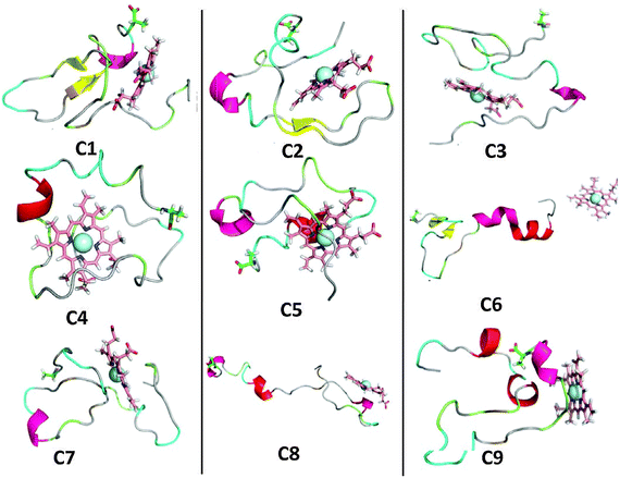 | ||
| Fig. 1 Cluster analysis of the Aβ–heme complex. The central portion of the first nine most dominant clusters of the 20 trajectories in the last 100 ns are shown in cartoon for protein, as sticks for heme and as a sphere for the Fe ion. Note that the C-terminals of the Aβ peptide are indicated as sticks. | ||
| Clusters | Population (%) | Trajectory | Surrounding residuesa |
|---|---|---|---|
| a The residues that are within 5 Å of the Fe ion. | |||
| C1 | 62.27 | traj4 | Phe-4 Leu-17 Ile-32 Ile-41 |
| C2 | 58.02 | traj9 | Phe-4 Phe-20 Val-24 Ile-31 Leu-34 Met-35 |
| C3 | 54.79 | traj15 | Phe-4 Arg-5 His-6 Phe-19 Phe-20 |
| C4 | 54.37 | traj14 | Arg-5 Leu-17 Phe-19 Val-24 |
| C5 | 51.85 | traj16 | Phe-4 Arg-5 Ile-31 Leu-34 Met-35 |
| C6 | 45.91 | traj13 | |
| C7 | 39.25 | traj3 | Phe-4 His-6 Ile-32 Gly-33 Met-35 |
| C8 | 38.57 | traj2 | Gln-15 Lys-16 Val-18 |
| C9 | 36.60 | traj17 | Met-35 |
In order to identify the residues that surround heme, wrappers were introduced to define the residues within 0.5 nm from the center of mass (COM) of the heme or the Fe ion. From Fig. 2, we observe that there are three possible sets of wrappers. The first set consists of residues Ala-2–His-6, the second set is made up of Gln-15–Phe-20, while the third set is Ala-30–Val-36. By ranking the residues according to their propensity to locate near heme, we detect the following order: Phe having the highest affinity, followed by Val, Ile, Leu, Met, Arg, His, … (see ESI,† Table S2). Remarkably, we observe that the set of residues that have the greatest tendency to lie in the neighborhood of heme are mainly aromatic and hydrophobic residues. This has led us to surmise that the hydrophobic interaction plays a dominant role in the Aβ–heme complex formation.
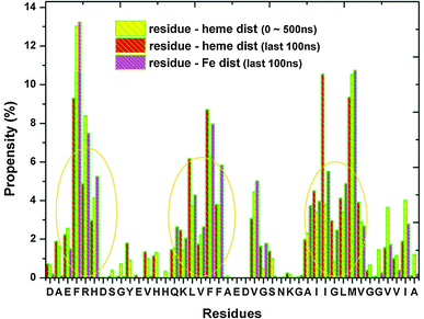 | ||
| Fig. 2 A plot of the propensity of residues to appear within 0.5 nm away from heme/Fe of the first 9 most dominant clusters. The red and yellow bars are calculated based on the whole simulation time and the last 100 ns respectively. The purple bar indicates the occurrence of residues within 0.5 nm away from Fe in the last 100 ns. | ||
3.2 Potential of mean forces
In order to provide a more comprehensive view on how the set of high propensity residues situate near (or interact with) the heme molecule, we plot the potential of mean forces (PMF) between these residues and heme. This is performed through the extensive Aβ–heme configurations that we have obtained from our simulations.51Fig. 3 shows the PMFs for the residues His, Phe, Leu, Ile, Val, Arg and Met of Aβ with respect to the Fe ion. The PMF shows that the His-6 has a basin of attraction located around the His-6–Fe minimum distance of 5 Å, which is absent in the case of the His-13 and His-14 residues. For the three histidines, the global minimum is located within the range of 10–17 Å. On the other hand, the global minimum of Phe-4 is located around 5.8 Å; Phe-19 is located around 4.5 Å; and Phe-20 is around 12.6 Å. We observe that Leu-17 and Leu-34 share a similar basin in the range of 7–10 Å. For Ile-32, the global minimum is located around 6.7 Å. As for Ile-31, it is located around 9.7 Å. But for the residue Ile-41, we observe a wide basin of attraction. In the case of Val-24, the first minimum appears around 6 Å, with another basin appearing in the range 11 Å to 23 Å. Note that the first potential barrier of Val-24 corresponds to the basin of Val-18. Arg-5 is observed to have a jagged PMF curve while Met-35 has several minima with its global minimum located around 4.6 Å. In conclusion, we observe that hydrophobic residues such as Phe, Val, Leu, IIe of Aβ tend to situate close to heme through the PMF curves. In particular, Phe-19, Met-35 and His-6 are found to have a high possibility of interacting with the heme group at close distance.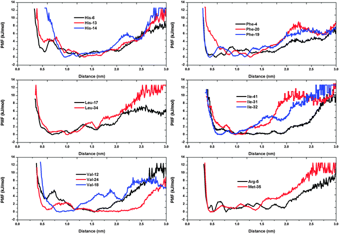 | ||
| Fig. 3 Potential of mean force (in kJ mol−1). | ||
3.3 Hydrogen bond formation between Aβ and heme
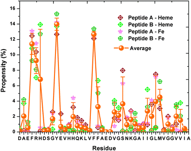
We have also obtained information on the hydrogen bond formation between heme and Aβ through the 20 trajectories. We observe that the four N atoms of heme have equal probability of being the hydrogen bond acceptor, while the O atoms of the heme –COOH groups have a much higher chance (more than 3 times) as the hydrogen bond acceptor (see ESI,† Table S3). A ranking of Aβ residues in terms of hydrogen bonding affinity from highest to lowest is as follows: Arg-5, Asp-1, His-14, His-6, Lys-16 (see Fig. 4). Interestingly, the highly ranked residues are observed to be neighbours to the identified residues which locate in close vicinity to heme. For example, Arg-5 is situated next to Phe-4 and we know that Phe-4 has a stronger propensity to form the Aβ–heme complex than Arg-5. Thus, our results show that hydrophobic interaction is the main force that drives the formation of the Aβ–heme complex, while the hydrogen bond interaction serves as an auxiliary force to stabilize the complex. Finally, we notice through our simulation that the Aβ N-terminus has a slight preference to form hydrogen bonds with heme than the C-terminus.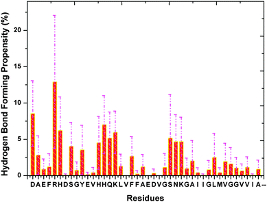 | ||
| Fig. 4 The binding propensity of heme towards Aβ residues. The purple dashed lines indicate the error bars. | ||
3.4 Aβ secondary structure propensity in the presence/absence of heme
The secondary structure propensity of each residue was examined from the 20 “heme-present” trajectories, 2 “heme-absent” trajectories (see Fig. 5 and ESI,† Fig. S3). Four types of secondary structures: β-structure (β-bridge and β-sheet); helix (α-helix and 3-helix); bend & turn; and coil, are used to categorize the secondary structure propensity. From Fig. 5, we can see that the residues His-6, Asp-7, Tyr-10, Glu-11, Val-12, Ala-21, Glu-22 and Asp-23 have a high probability of being involved in the β-structure conformations. On the other hand, the residues Ser-26, Asn-27, Lys-28, Gly-29 and Ala-30 show a strong preference in participating in the helical conformations. By examining the number of residues that adopt the β-structure and the helical structures in our simulation, we see that the presence of heme has the effect of reducing the β-content and increasing the helical-content by 22.1% and 33.6% respectively (see ESI,† Fig. S4).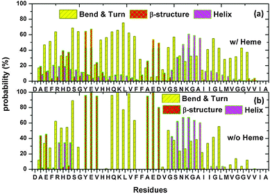 | ||
| Fig. 5 Aβ secondary structure propensity with heme (a) and without heme (b), was examined by averaging over all trajectories every 5 fs. The average statistical error is found to be less than 0.18. | ||
3.5 Aβ–hemes complex
In order to examine the possible heme-binding Aβ motifs during the process of Aβ oligomerization for the 2 Aβ + 4 hemes system, clustering analysis was carried out on the 16 trajectories with a Cα-rmsd cutoff of 3 Å. The central portions of the first 9 dominant clusters are shown in Fig. 6 as well as the population of these 9 dominant clusters. The Aβ residues that surround the Fe ion from heme are given in Table 2.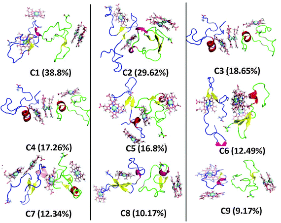 | ||
| Fig. 6 Cluster analysis of the Aβ–hemes complex. The central portions of the first six most dominant clusters are shown in cartoon for protein (blue: peptide A; green: peptide B), as sticks for heme and as a sphere for the Fe ion. The C-terminals of Aβ are distinguished by sticks. | ||
| Clusters | Trajectory | Surrounding residuesa |
|---|---|---|
| a The residues that are within 5 Å of the Fe ion. | ||
| C1 | 11 | Peptide A: Phe-4 Tyr-10 Phe-19 Val-39 ILE-41 |
| Peptide B: Val-39 | ||
| C2 | 11 | Peptide A: Val-18 Asn-27 Gly-37 Gly-38 Ile-41 |
| Peptide B: His-6 Asp-7 Gly-9 Ile-31 Met-35 Val-39 | ||
| C3 | 8 | Peptide A: Phe-4 Arg-5 Glu-11 His-14 |
| Peptide B: Phe-4 Val-12 Leu-17 Met-35 Val-39 | ||
| C4 | 15 | Peptide A: Ala-2 Phe-4 Tyr-10 Leu-17 Phe-19 Leu-34 Met-35 Val-36 |
| Peptide B: His-13 Leu-17 Phe-19 Ile-31 | ||
| C5 | 13 | Peptide A: Arg-5 His-6 Tyr-10 His-14 Gln-15 Ile-32 Met-35 Val-39 |
| Peptide B: Glu-3 Phe-4 Ile-32 Leu-34 Met-35 | ||
| C6 | 15 | Peptide A: Leu-17 Phe-19 Leu-34 Met-35 |
| Peptide B: His-13 Leu-17 Phe-19 Val-39 | ||
| C7 | 13 | Peptide A: Arg-5 His-6 Asp-7 Ser-8 Gly-9 Tyr-10 His-14 Gln-15 Met-35 Val-36 Val-39 |
| Peptide B: Ala-2 Glu-3 Phe-4 Ile-31 Ile-32 Met-35 | ||
| C8 | 6 | Peptide A: Phe-4 Phe-19 Val-24 Gly-25 Ser-26 Val-39 |
| Peptide B: Leu-17 Phe-19 Ile-32 | ||
| C9 | 6 | Peptide A: Phe-4 Tyr-10 Phe-19 Val-39 Ile-40 |
| Peptide B: Val-39 | ||
Our results show that the residues, which are 0.5 nm away from the COM of heme as shown in Fig. 7, display the following affinity to reside in the neighbourhood of heme from highest to lowest: Phe, Tyr, Arg, His, Ser, Leu, Met…. On the other hand, the Aβ residues that tend to lie within 0.5 nm of the Fe ions of heme have the following affinity ranking: with Phe having the highest affinity, followed by Tyr, Arg, His, Met, Leu, Ser…. We see that the Aβ residues that occur in the vicinity of heme and the Fe ions are slightly different for the 2 Aβ + 4 hemes system and the 1 Aβ+1 heme system. The differences result from interactions between Aβ peptides which affect the Aβ–heme complex motifs. Remarkably, we observe that the residue Phe shows the highest interaction affinity with hemes in both systems.
 | ||
| Fig. 7 The occurrence of Aβ residues within 0.5 nm heme/Fe. The average propensity of each residue towards all the 4 hemes/Fe ions are indicated by the orange balls and connected via the orange lines. | ||
Furthermore, the hydrogen bond forming propensity of the Aβ residues towards heme were also examined (see Fig. 8). Our results show that the Aβ residues share similar propensity in hydrogen bond formation in the 2 Aβ + 4 hemes and the 1 Aβ + 1 heme simulations, albeit with the ranking Lys-16, Ser-26, Arg-5, Lys-28, His-6…. As a final note, we notice a smaller standard deviation error in Fig. 8 as compared to Fig. 4 which is for the 1 Aβ + 1 heme system. This results from the presence of extra heme molecules in the 2 Aβs+4 hemes system, which can be observed from the ratio of Aβ to heme being 2:1 in this system, versus the 1:1 ratio in the 1 Aβ + 1 heme system.
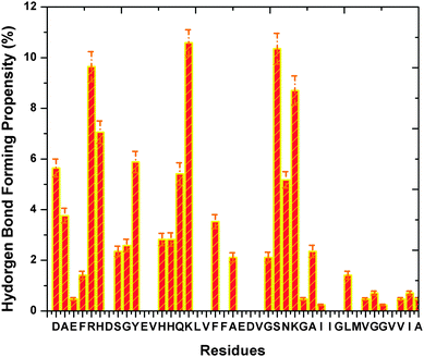 | ||
| Fig. 8 The binding propensity of hemes towards Aβ residues. | ||
3.6 Heme physically prevents Aβ aggregation
The secondary structure propensity of each residue of the 2 Aβ + 4 hemes system can be determined from Fig. 9. As before, four types of secondary structures are considered to categorize the secondary structure propensity of the system. The four types are: β-structure (β-bridge and β-sheet); helix (α-helix and 3-helix); bend & turn; and coil. For the sake of clarity, Fig. 9 only displays three of the four types, i.e., the β-structure, bend & turn, and the helix structure. By comparing Fig. 9 with Fig. 5(a), we observe the similar α-structure propensity for the 2 Aβ + 4 hemes system as the 1 Aβ + 1 heme system. For example, the sequence 26SNKGAI31 is found to be one common helical segment in both systems. By averaging the number of residues adopting the helical-structure and the β-structure every 50 ns (see Fig. 10), one finds that the presence of heme has not led to a significant difference in the secondary structure content of the 2 Aβ + 4 hemes system in comparison to the situation when heme is absent.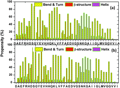 | ||
| Fig. 9 The secondary structure propensity of the Aβ peptide A (a) and peptide B (b). Note that the yellow bars are for the bend & turn, the red bars are for the β-structure, while the purple bars are for the helical structure. The propensity for the coil structure is, however, not shown. | ||
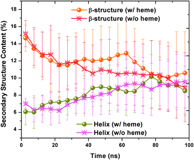 | ||
| Fig. 10 The number of residues adopting the β-structure and helical content in the presence/absence of heme was plotted after averaging over 16 trajectories every 50 ns. The statistical errors are indicated by error bars. | ||
The number of contacts between peptide A and peptide B are calculated for all the 32 trajectories. By averaging the number of contacts every 20 ns for the 16 “heme-present” trajectories and “heme-absent” trajectories, we found a lower contact number for the trajectories with the presence of heme in comparison with our group of controls (see Fig. 11(d)). This reduction in contact implies that the presence of heme has prevented the aggregation of Aβ. By extracting the last 10 ns of the 32 trajectories and plotting the averaged contact map (see Fig. 11(a) and (c)), we see that more contacts are formed in the Aβ peptides without heme than those with heme. In addition, we have plotted in Fig. 11(b) a representative Aβ–hemes complex to illustrate its secondary structure.
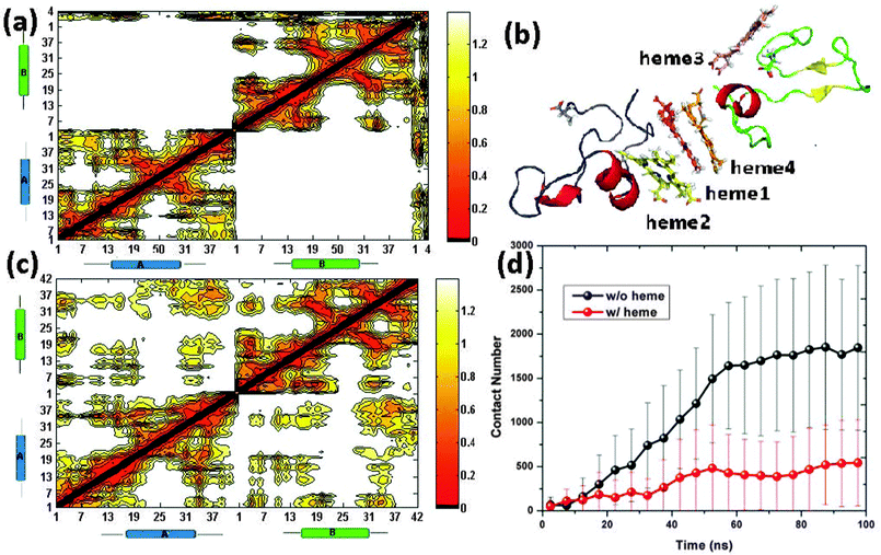 | ||
| Fig. 11 The contact map for peptide A, peptide B and heme (a). A representative structure of the Aβs–hemes complex with the four hemes being distinguished through different colors. Note that the loop of peptide A and peptide B are colored as blue and green respectively with the C-terminal Ala-42 being indicated as sticks (b). The contact map between peptide A and peptide B (c). A plot of the average number of contacts between peptide A and peptide B in the presence/absence of heme every 5 ns. Note that the error bars indicate the average derivation (d). | ||
4 Summary and discussion
The formation of dimer, trimer and higher order oligomers during the process of amyloid β aggregation is believed to be toxic to the neurons. In order to avert the resulting neuronal apoptosis, there is great interest in the study of the Aβ–heme complex which plays different roles in the intracellular and extracellular space. While the intracellular Aβ–heme complex is proposed to decrease heme bioavailability which leads to a deficiency of the functional heme,26,27 extracellular Aβ–heme is reported to inhibit Aβ aggregation and alleviate Aβ oligomer's toxicity.30Past research has uncovered several Aβ–heme motifs which mainly involve the histidine residues,27,35,52 without any analysis of the detailed secondary structure conformations within the configuration. By means of extensive conventional molecular dynamics simulations, we have identified several binding motifs which indicate that hydrophobic residues have a high tendency to interact with heme. Thus, an Aβ–heme complex may not be histidine-focusing, with the hydrophobic interactions between the heme and Aβ hydrophobic residues playing a dominant role in the Aβ–heme complex formation as shown in our MD simulations study. However, further experimental as well as QM/MM study is required to provide a more accurate assessment to elucidate whether Aβ–heme complex formation is driven via the interaction with histidine or by hydrophobic interaction. It is important to note that past experiment53 on the Aβ–heme complex involved peptides such as the Aβ1–40, Aβ1–16, Aβ17–40 and Aβ10–20, which are mainly non-amyloidogenic, while the toxic Aβ1–42 has yet to be tested experimentally. On the other hand, recent QM/MM studies54 on the Aβ–heme complex had only explored a limited number of configurations. Thus, we expect more work to be performed on QM/MM, experiments and MD simulations that aim to fully grasp the detailed interactions between heme and Aβ in the not too distant future.
Through the PMF, we observe that the position of the Aβ hydrophobic residues has an implicit effect on the binding affinity of heme towards certain residues. In addition, heme physically prevents the Aβ aggregation and it is also found to have an influence on the underlying secondary structure of Aβ during the formation of the Aβ–heme complex, which may explain its inhibitory role in neuronal cell death. The latter conclusion is supported by the simulation of the 2 Aβ + 4 hemes system, which demonstrates explicitly how heme physically prevents Aβ aggregation with an increase in the α-content within the peptides.
Acknowledgements
The authors would like to thank Hwee Jin Soh from the High Performance Computing Center for his kind help in the provision of computational support, and Dr See-Wing Chiu from UIUC for his suggestions and review of the preliminary draft. The support of research grants, URC(RG23/11), from Nanyang Technological University and the IDA Cloud Computing Call for Project Proposals 2012 is gratefully acknowledged.References
- L. Minati, T. Edginton, M. G. Bruzzone and G. Giaccone, Am. J. Alzheimers Dis. Other Dementia, 2009, 24, 95–121 CrossRef.
- A. C. Cuello, Brain Pathol., 2005, 15, 66–71 CrossRef CAS.
- J. Hardy and D. J. Selkoe, Science, 2002, 297, 353–356 CrossRef CAS.
- C. Venugopal, C. M. Demos, K. S. Rao, M. A. Pappolla and K. Sambamurti, CNS Neurol. Disord.: Drug Targets, 2008, 7, 278–294 CAS.
- C. Haass and D. J. Selkoe, Nat. Rev. Mol. Cell Biol., 2007, 8, 101–112 CrossRef CAS.
- Q. Wang, D. M. Walsh, M. J. Rowan, D. J. Selkoe and R. Anwyl, J. Neurosci., 2004, 24, 3370–3378 CrossRef CAS.
- Y. Shafrir, S. Durell, N. Arispe and H. R. Guy, Proteins: Struct., Funct., Bioinf., 2010, 78, 3473–3487 CrossRef CAS.
- L. N. Zhao, H. Long, Y. Mu and L. Y. Chew, Int. J. Mol. Sci., 2012, 13, 7303–7327 CrossRef CAS.
- L. N. Zhao, S.-W. Chiu, J. Benoit, L. Y. Chew and Y. Mu, J. Phys. Chem. B, 2011, 115, 12247–12256 CrossRef CAS.
- G. M. Shankar, S. M. Li, T. H. Mehta, A. Garcia-Munoz, N. E. Shepardson, I. Smith, F. M. Brett, M. A. Farrell, M. J. Rowan, C. A. Lemere, C. M. Regan, D. M. Walsh, B. L. Sabatini and D. J. Selkoe, Nat. Med., 2008, 14, 837–842 CrossRef CAS.
- L. N. Zhao, S.-W. Chiu, J. Benoit, L. Y. Chew and Y. Mu, J. Phys. Chem. B, 2012, 116, 7428–7435 CrossRef CAS.
- F. J. Sepulveda, J. Parodi, R. W. Peoples, C. Opazo and L. G. Aguayo, PLoS One, 2010, 5, e11820 Search PubMed.
- Y. Avramovich-Tirosh, T. Amit, O. Bar-Am, O. Weinreb and M. B. Youdim, BMC Neurosci., 2008, 9, S2 CrossRef.
- P. W. Mantyh, J. R. Ghilardi, S. Rogers, E. DeMaster, C. J. Allen, E. R. Stimson and J. E. Maggio, J. Neurochem., 1993, 61, 1171–1174 CrossRef CAS.
- M. A. Lovell, J. D. Robertson, W. J. Teesdale, J. L. Campbell and W. R. Markesbery, J. Neurol. Sci., 1998, 158, 47–52 CrossRef CAS.
- A. I. Bush and R. E. Tanzi, Neurotherapeutics, 2008, 5, 421–432 CrossRef CAS.
- D. G. Smith, R. Cappai and K. J. Barnham, Biochim. Biophys. Acta, Proteins Proteomics, 2007, 1768, 1976–1990 CrossRef CAS.
- B. Halliwell and J. M. Gutterer, Free Radicals in Biology and Medicine, Oxford University Press, USA, 1999 Search PubMed.
- K. Honda, G. Casadesus, R. B. Petersen, G. Perry and M. A. Smith, Ann. N. Y. Acad. Sci., 2006, 1012, 179–182 CrossRef.
- C. A. Rottkamp, A. K. Raina, X. Zhu, E. Gaier, A. I. Bush, C. S. Atwood, M. Chevion, G. Perry and M. A. Smith, Free Radical Biol. Med., 2001, 30, 447–450 CrossRef CAS.
- G. Liu, P. Men, W. Kudo, G. Perry and M. A. Smith, Neurosci. Lett., 2009, 455, 187–190 CrossRef CAS.
- R. J. Castellani, P. I. Moreira and G. P. X. Zhu, BioFactors, 2012, 38, 133–138 CrossRef CAS.
- S. Kumar and U. Bandyopadhyay, Toxicol. Lett., 2005, 157, 175–188 CrossRef CAS.
- A. G. Smith, E. L. Raven and T. Chernova, Metallomics, 2011, 3, 955–962 RSC.
- S. Hou, M. F. Reynolds, F. T. Horrigan, S. H. Heinemann and T. Hoshi, Acc. Chem. Res., 2006, 39, 918–924 CrossRef CAS.
- H. Atamna and W. H. F. II, Proc. Natl. Acad. Sci. U. S. A., 2004, 101, 11153–11158 CrossRef CAS.
- H. Atamna and K. Boyle, Proc. Natl. Acad. Sci. U. S. A., 2006, 103, 3381–3386 CrossRef CAS.
- E. M. Mutisya, A. C. Bowling and M. F. Beal, J. Neurochem., 1994, 63, 2179–2184 CrossRef CAS.
- W. D. J. Parker, J. Parks, C. M. Filley and B. K. Kleinschmidt-DeMasters, Neurology, 1994, 44, 1090–1096 CrossRef.
- Q. Bao, Y. Luo, W. Li, X. Sun, C. Zhu, P. Li, Z.-X. Huang and X. Tan, J. Biol. Inorg. Chem., 2011, 16, 809–816 CrossRef CAS.
- C. Yuan, L. Yi, Z. Yang, Q. Deng, Y. Huang, H. Li and Z. Gao, J. Biol. Inorg. Chem., 2012, 17, 197–207 CrossRef CAS.
- J. M. Stevens, T. Uchida, O. Daltrop and S. J. Ferguson, Biochem. Soc. Trans., 2005, 33, 792–795 CrossRef CAS.
- C. Sanders, S. Turkarslan, D.-W. Lee and F. Daldalsend, Trends Microbiol., 2010, 18, 266–274 CrossRef CAS.
- J. M. Aramini, K. Hamilton, P. Rossi, A. Ertekin, H. Lee, A. Lemak, H. Wang, R. Xiao, T. B. Acton, J. K. Everett and G. T. Montelione, Biochemistry, 2012, 51, 3705–3707 CrossRef CAS.
- H. Atamna, J. Bioenerg. Biomembr., 2009, 41, 457–464 CrossRef CAS.
- O. Crescenzi, S. Tomaselli, R. Guerrini, S. Salvatori, A. M. D'Ursi, P. A. Temussi and D. Picone, Eur. J. Biochem., 2002, 269, 5642–5648 CrossRef CAS.
- J. C. Gordon, J. B. Myers, T. Folta, V. Shoja, L. S. Heath and A. Onufriev, Nucleic Acids Res., 2005, 33, 368–371 CrossRef.
- J. Myers, G. Grothaus, S. Narayanan and A. Onufriev, Proteins, 2006, 63, 928–938 CrossRef CAS.
- J. J. Irwin and B. K. Shoichet, J. Chem. Inf. Model., 2005, 45, 177–182 CrossRef CAS.
- P. Bjelkmar, P. Larsson, M. A. Cuendet, B. Hess and E. Lindahl, J. Chem. Theory Comput., 2010, 6, 459–466 CrossRef CAS.
- B. Hess, H. Bekker, H. J. C. Berendsen and J. G. E. M. Fraaije, J. Comput. Chem., 1997, 113, 1463–1472 CrossRef.
- S. Nosé, Mol. Phys., 1984, 55, 255–268 CrossRef.
- W. G. Hoover, Phys. Rev. A, 1985, 31, 1695–1697 CrossRef.
- U. Essmann, L. Perera, M. L. Berkowitz, T. Darden, H. Lee and L. G. Pedersen, J. Chem. Phys., 1995, 103, 8577–8593 CrossRef CAS.
- H. J. C. Berendsen, D. van der Spoel and R. van Drunen, Comput. Phys. Commun., 1995, 91, 43–56 CrossRef CAS.
- E. Lindahl, B. Hess and D. van der Spoel, J. Mol. Model., 2001, 7, 306–317 CAS.
- D. V. D. Spoel, E. Lindahl, B. Hess, G. Groenhof, A. E. Mark and H. J. C. Berendsen, J. Comput. Chem., 2005, 26, 1701–1718 CrossRef.
- W. L. DeLano, The PyMOL Molecular Graphics System, Version 1.4, Schrödinger, LLC, 2011 Search PubMed.
- W. Humphrey, A. Dalke and K. Schulten, J. Mol. Graphics, 1996, 14, 33–38 CrossRef CAS.
- X. Daura, K. Gademann, B. Jaun, D. Seebach, W. F. van Gunsteren and A. E. Mark, Angew. Chem., Int. Ed., 1999, 38, 236–240 CrossRef CAS.
- W. Xu, C. Zhang, P. Derreumaux, A. Graslund, L. Morozova-Roche and Y. Mu, PLoS One, 2011, 6, e24329 CAS.
- Y. Zhou, J. Wang, L. Liu, R. Wang, X. Lai and M. Xu, ACS Chem. Neurosci., 2013, 4, 535–539 CrossRef CAS.
- D. Pramanik and S. G. Dey, J. Am. Chem. Soc., 2011, 133, 81–87 CrossRef CAS.
- S. Azimi and A. Rauk, J. Chem. Theory Comput., 2012, 8, 5150–5158 CrossRef CAS.
Footnote |
| † Electronic supplementary information (ESI) available. See DOI: 10.1039/c3cp52354c |
| This journal is © the Owner Societies 2013 |