Matrix and interaction effects on the magnetic properties of Co nanoparticles embedded in gold and vanadium
M.
Ruano
a,
M.
Díaz
a,
L.
Martínez
a,
E.
Navarro
b,
E.
Román
a,
M.
García-Hernandez
a,
A.
Espinosa
a,
C.
Ballesteros
c,
R.
Fermento
d and
Y.
Huttel
*a
aInstituto de Ciencia de Materiales de Madrid (ICMM-CSIC), c/Sor Juana Inés de la Cruz, 3, 28049 Cantoblanco, Madrid, Spain. E-mail: huttel@icmm.csic.es
bDpto. de Física de Materiales, Universidad Complutense de Madrid (UCM), Av. Complutense s/n, 28040 Madrid, Spain
cDpto. de Física, EPS, Universidad Carlos III, Madrid, 28911, Madrid, Spain
dIMM-Instituto de Microelectrónica de Madrid (CNM-CSIC), Isaac Newton 8, PTM, E-28760 Tres Cantos, Madrid, Spain
First published on 2nd November 2012
Abstract
The study of the magnetic properties of Co nanoparticles (with an average diameter of 10.3 nm) grown using a gas-phase aggregation source and embedded in Au and V matrices is presented. We investigate how the matrix, the number of embedded nanoparticles (counted by coverage percentage), the interparticle interactions and the complex nanoparticles/matrix interface structure define the magnetic properties of the studied systems. A threshold coverage of 3.5% of a monolayer was found in both studied systems: below this coverage, nanoparticles behave as an assembly of independent single-domain magnetic entities with uniaxial anisotropy. Above the threshold it is found that the magnetic behavior of the systems is more matrix dependent. While magnetic relaxation and Henkel plots measurements stress the importance of the dipolar interactions and the formation of coherent clusters in the case of the Au matrix, the magnetic behavior of cobalt clusters embedded in the vanadium matrix is explained through the formation of a spin glass-like state at the V–Co interface that screens the magnetic interactions between NPs.
I. Introduction
Magnetism of nanoparticles has become one of the main research forefronts. Telecommunications,1 catalysis2 or photonics3 represent some of the research fields that have experienced an intense development thanks to the advances in nanoscience. Also the increasing necessity for materials that can be used as magnetic media in high-density magnetic data storage devices has attracted attention towards single-domain magnetic nanoparticles with uniaxial anisotropy.4 Due to the fact that magnetic nanoparticles exhibit unique properties induced by the high surface/volume ratio, nanoscale magnetic materials have offered a new range of applications in the last few decades, e.g., as high-density magnetic storage media,5,6 and in the fields of drug delivery,7 magnetic resonance imaging8 and high-frequency electronics,9 from the technological viewpoint, whereas from a fundamental interest, features such as magnetic quantum tunneling have been studied.10In the case of bulk defect-free materials, the intrinsic magnetic properties (e.g., saturation magnetization Ms, coercive field Hc and Curie temperature Tc) only depend on the chemical and crystallographic structure. The size and shape factors of bulk systems are not relevant to their final properties11 and volume anisotropy is mainly determined by the magnetocrystalline anisotropy. However, when at least one of the dimensions of the studied system is reduced to the nanometer scale, the magnetic properties are strongly influenced by finite-size and surface effects. Finite-size effects result from quantum confinement of the electrons while surface effects arise from symmetry breaking at the boundaries of the particle (i.e., lower number of coordinated atoms) and determine the surface magnetic anisotropy.12 Hence, the progressive size reduction of the magnetic entities results in magnetic behaviors that are primarily dominated by the particle surface spins.13
Apart from the intrinsic properties of nanoparticles, the surrounding material in contact with nanoparticles also plays an important role in the final properties of the system.14,15 The understanding of the effect of such surrounding material (capping or matrix) is a key point for the use of nanoparticles because most of the nanoparticles cannot be used freely but need to be inserted in more complex systems. Surface and confinement effects produce novel optical, magnetic or dielectric properties in nano-sized metals, which enable the possibility of using these nanostructures for technological applications by embedding them into appropriate matrices.16–19 Magnetic nanoparticles embedded into matrices are expected to be used in a wide range of applications such as optical devices with high magneto-optical activity and low optical absorption,20,21 in high-density magnetic data storage or high frequency devices,22–24 and in plasmonic applications,25 among others.26–28 The gas-phase deposition technique is increasingly used in order to produce the desired nanocomposites, probably due to its versatility in producing high purity nanocomposites with the ability to fine-tune the size distribution and concentration of the nanoparticles. An increasing number of studies on magnetic nanoparticles grown using this technique and embedded in different matrices can be found in the literature including Co29–38 Ni,38,39 Fe31,37,38,40 and alloy37,38,41–43 nanoparticles. Magnetic nanoparticles of 3d transition metals (usually Fe, Ni and Co) in contact with non-ferromagnetic matrices present an interfacial anisotropy,44 whose origin strongly depends on the electronic structure of the nanoparticles, the matrix magnetic behavior and the interparticle interaction energies. Embedding nanoparticles can lead to encapsulation effects that prevent unwanted effects such as agglomeration and, therefore, the increase of effective magnetic size. Moreover spin disorder at the surface of the nanoparticles, not totally explained by the existence of dipolar interactions between particles,45 can lead to more complex systems with spin-glass states and random canting.46 The magnetic characterization of these systems has put forward the controversial issue of distinguishing between the intrinsic properties of the particle itself or collective behavior induced by interparticle interactions.47,48 Nevertheless, it is striking the lack of detailed knowledge about the relationships between nanoparticles morphology (shape/size distribution) and their geometrical arrangement, long-range interparticle interactions and local couplings, the matrix/nanoparticle interfaces and their intrinsic magnetic properties. The analysis of the interparticle distances is essential for the detailed understanding of any magnetic system made of nanoparticles.
In the present work, we will focus on the influence of interparticle interactions on the magnetic behavior of Co nanoparticles (Co NPs) grown using a gas-phase aggregation source or Ion Cluster Source (ICS) and embedded in Au and V matrices, from physically isolated particles to 10.6% of a nominal monolayer coverage. In addition to the study of the matrix influence on the magnetic interactions between nanoparticles, another motivation of the study is to investigate the dependence between spatial distribution of nanoparticles and the magnetic response of the systems. Gold has been selected as an ideal non-reactive matrix that prevents the Co NPs oxidation and also exhibits a weak polarization in contact with 3d transition metals.49 Hence, the Co NPs embedded in an Au matrix are expected to preserve most of their intrinsic magnetic properties. On the other hand, vanadium, which is paramagnetic, can exhibit non-zero magnetization under certain conditions such as loss of coordination, when its atomic volume is increased, or in contact with 3d ferromagnetic materials, despite its large paramagnetic susceptibility.50,51 Co nanoparticles have been embedded in metallic hosts such as Pt,44 Nd,52 Cu,53 Mn,54 Ag55 and Au.33 On the other hand, although there are several studies of Co/V multilayers,56–67 as far as we know, the magnetic properties of Co NPs embedded in the metallic vanadium matrix have not been reported. We will firstly investigate the morphology of Co nanoparticles deposited on flat Si(100) surfaces and calculate the occupation in terms of coverage percentage of a monolayer. We report on the magnetic behavior of different coverage percentages of a monolayer of Co NPs embedded in Au and V matrices and the evolution of the magnetic properties as a function of coverage percentage, paying special attention to the influence of magnetic interparticle interactions as well as the NP/matrix interface effects.
II. Experimental details
The samples were fabricated combining the use of an ICS68 and magnetron sputtering sources in an Ultra High Vacuum (UHV) system with base pressure in the low 10−9 mbar. Two series of samples were fabricated on Si(100) substrates. The first one consisted of cobalt nanoparticles embedded in two gold thin films, with nominal thickness of 40 nm [Si(100)/40 nm Au/CoNPs/40 nm Au]. The second series of samples consisted of cobalt nanoparticles embedded in two vanadium thin films, with 15 nm nominal thickness and encapsulated in two Au 40 nm thick layers in order to prevent the oxidation [Si(100)/40 nm Au/15 nm V/CoNPs/15 nm V/40 nm Au]. All the samples were grown at room temperature on naturally oxidized Si(100) substrates and outgassed in situ for 30 minutes at 423 K before deposition. Co nanoparticles were fabricated with the ICS and using a Co target of 99.95% purity. The typical applied power to the magnetron was 50 W. During deposition, the pressure was in the low 10−5 mbar in the UHV system. Au and V thin films were deposited by DC magnetron sputtering using Au and V targets of 99.99% and 99.7% respectively. Ar pressure during the sputtering process was in the low 10−3 mbar. Au and V magnetrons were operated at 20 W and the deposition rates were 0.2 nm s−1 and 0.02 nm s−1 for Au and V, respectively.Atomic force microscopy (AFM) measurements were performed using the Cervantes AFM System from Nanotec Electrónica S.L.69 The AFM images have been recorded in the dynamic mode. Commercial silicon AFM tips were employed with a typical radius less than 7 nm. AFM images were recorded on samples where Co nanoparticles were directly deposited on Si substrates. The analysis of the images was carried out using a combination of the WSxM70 and ImageJ software programs.71
Transmission electron microscopy (TEM) measurements were performed in a Philips Tecnai 20F FEG analytic microscope, operating at 200 kV, equipped with an energy dispersive X-ray (EDX) analysis system and a scanning transmission electron microscopy (STEM) modulus with a high angle annular dark field (HAADF) detector for Z-contrast images. The measurements have been performed on plan-view images of Co nanoparticles deposited on carbon-coated TEM grids. The analysis of the TEM images was performed with the ImageJ software.
Magnetic measurements have been performed in a Superconducting Quantum Interference Device (SQUID) Magnetometer from Quantum Design and equipped with a 5 Tesla (50 kOe) coil. Magnetic field was applied parallel to the sample surface. The samples were demagnetized before measurements. The evolution of the magnetization with temperature was measured by applying a magnetic field of 1.5 kOe (which is in the linear response regime) from 1.8 K to room temperature, under Field Cooled (FC) and Zero-Field Cooled (ZFC) protocols. Magnetization loops have been measured at 10 K after ZFC and FC and at 300 K. The diamagnetic contribution of the Si substrates has been measured for further subtraction from the raw data. For magnetic relaxation measurements, samples were cooled from room temperature to 5 K in 5 T applied field. Magnetization signal as a function of time has been measured every 5 minutes for approximately 2 hours. Henkel plots have been measured by ΔM technique,72 based on the comparison of the isothermal remanent magnetization (IRM) and direct current demagnetization (DCD) curves. ΔM(H) curves have been calculated using the measured DCD(H) and IRM(H) at 5 K.
III. Results and discussion
(a) Morphological characterization of Co nanoparticles deposits
In Fig. 1a, c and e we present representative AFM images of Co nanoparticles deposits on Si(100) substrates with different surface coverages. These AFM measurements were made in order to calibrate and check the reproducibility of nanoparticles deposits before matrix incorporation. The insets correspond to the profiles extracted from the AFM images (blue lines). AFM images recorded over large areas (1 μm2) were not only measured at the center of the samples, but also at several random positions on each sample to check the homogeneity of the samples. The deposition time has been varied in order to obtain different coverage percentages, ranging from 2.4% to 10.6% of a monolayer. The surface concentration has been determined assuming that 100% surface concentration corresponds to a hexagonal close packed (hcp) array of nanoparticles. In the case of nanoparticles of diameter 10.3 nm, a surface of 1 μm2 contains 10![[thin space (1/6-em)]](https://www.rsc.org/images/entities/char_2009.gif) 732 nanoparticles in one monolayer of particles arranged in an hcp array. Since the number of nanoparticles per μm2 in Fig. 1a, c and e is approximately 260, 576, and 1135, the corresponding surface coverages are close to 2.4%, 5.4%, and 10.6% respectively. Due to the intrinsic convolution between the AFM tip shape and the nanoparticles, in AFM images the coverage of the nanoparticles appears to be higher than the measured one.73 This inherent feature of AFM affects the acquired surface topography image. In order to avoid further confusion, we display the distribution of the nanoparticles over the surface, in the three AFM examples presented: 2.4% (Fig. 1b), 5.4% (Fig. 1d), and 10.6% (Fig. 1f). For such representation we have replaced each nanoparticle identified by AFM by a dot with diameter 10 nm (mean diameter). These representations give a better view of the real density and distribution of the nanoparticles despite the approximation that the nanoparticles have a diameter of 10 nm. Fig. 1b, d and f clearly show that the nanoparticles do not form systematically bigger agglomerates even at high coverages.
732 nanoparticles in one monolayer of particles arranged in an hcp array. Since the number of nanoparticles per μm2 in Fig. 1a, c and e is approximately 260, 576, and 1135, the corresponding surface coverages are close to 2.4%, 5.4%, and 10.6% respectively. Due to the intrinsic convolution between the AFM tip shape and the nanoparticles, in AFM images the coverage of the nanoparticles appears to be higher than the measured one.73 This inherent feature of AFM affects the acquired surface topography image. In order to avoid further confusion, we display the distribution of the nanoparticles over the surface, in the three AFM examples presented: 2.4% (Fig. 1b), 5.4% (Fig. 1d), and 10.6% (Fig. 1f). For such representation we have replaced each nanoparticle identified by AFM by a dot with diameter 10 nm (mean diameter). These representations give a better view of the real density and distribution of the nanoparticles despite the approximation that the nanoparticles have a diameter of 10 nm. Fig. 1b, d and f clearly show that the nanoparticles do not form systematically bigger agglomerates even at high coverages.
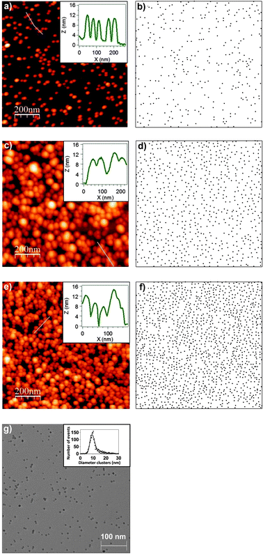 | ||
| Fig. 1 1 μm × 1 μm AFM images of 2.4% (a), 5.4% (c) and 10.6% (e) surface coverage of cobalt nanoparticle deposits onto Si(100) substrates. Each coverage percentage is in terms of a monolayer. Insets correspond to the profiles extracted from the blue lines in the AFM images. AFM equivalent representation displaying the distribution of the nanoparticles in the case of 2.4% (b), 5.4% (d) and 10.6% (f) where each nanoparticle identified by an AFM image is a dot with diameter 10 nm. (g) 550 × 550 nm2 TEM image of Co nanoparticles deposited on a TEM grid. Inset corresponds to diameter histogram obtained from the statistical events of several TEM images. A lognormal distribution has been performed as a fitting function. | ||
Nevertheless, while the lateral convolution in AFM leads to such an apparent bigger diameter of each nanoparticle, the determination of the height is very accurate and has been used for the determination of the nanoparticle size. The size homogeneity and the surface coverage of the deposits were checked by measuring several AFM images at different positions on relatively large samples (25 mm2). As it can be observed in the nanoparticles height distribution presented in ref. 35 (i.e., the same nanoparticles were embedded into a silicon oxide matrix), the mean average height is 10.3 ± 1.8 nm. The low standard deviation indicates that the height distribution is homogeneous in the sense that the deviation from the mean diameter is low. Therefore, not only the random distribution of the nanoparticles (homogeneous distribution over the substrates) but also the low deviation from the mean height (homogeneous distribution of height) was checked systematically on a number of deposits, proving the homogeneity of the deposits and the reproducibility of the fabrication of the samples.
A representative example TEM image is displayed in Fig. 1g in order to illustrate the mentioned size homogeneity and good homogeneity of nanoparticles distribution. The inset corresponds to the diameter distribution of the nanoparticles extracted from several TEM images. As can be observed, the TEM image is very similar to the representations of the nanoparticles over the surface (Fig. 1b, d and f). The diameter distribution is homogeneous (low deviation from the mean diameter) and the nanoparticles are homogeneously distributed over the surface (random distribution). Moreover, Co nanoparticles present a polycrystalline hcp structure with some presence of fcc structure in nanoparticles smaller than 3 nm.35,74
According to AFM and TEM measurements, nanoparticles have sizes that do not differ significantly from the mean size and are distributed homogeneously. In other words, the nanoparticles have a 10.3 ± 2.0 nm average diameter, with the same dimension in and out of the substrate plane, which implies a “soft-landing” of the NPs on the substrate.
(b) Interparticle distances study
A detailed analysis of the interparticle distances (first, second and third neighbors) was performed as an attempt to find out the critical distance at which the nanoparticles start behaving collectively instead of individual entities as well as the geometrical factors that influence the magnetic response of the studied systems. To this purpose, a study of the interparticle distances has been performed with the statistical events of several AFM images of 1 μm2 area acquired on samples of Co NPs deposited directly on Si(100) substrates. The number of AFM images required for this analysis was dependent on the coverage percentage and ranged from three to six.First, second and third neighbor's distances are related to the three nearest nanoparticles around each nanoparticle (see Fig. 2a). The analysis was carried out under the initial hypothesis of nanoparticles with spherical morphology and with a diameter of 10.3 nm as determined by AFM and TEM. By means of the ImageJ software the (xi,yi) coordinates of each of the N nanoparticles in the AFM images were extracted (N is the total number of nanoparticles in the analyzed 1 μm2 AFM image). Equivalent AFM images are displayed for representative surface coverages in Fig. 1b, d and f. In addition, Fig. 1d and f show that our statistical analysis can be employed at high coverage percentages.
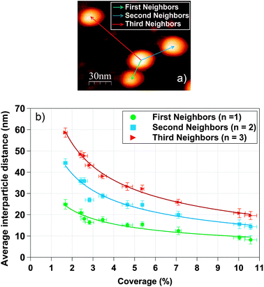 | ||
| Fig. 2 (a) Schematic definition of first, second and third neighbors distance using an AFM image. (b) Representation of the experimental first, second and third neighbors interparticle average distance as a function of the coverage percentage. | ||
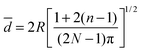
With the set of coordinates, the first, second and third neighbor's distances from each nanoparticle were calculated and the mean particle diameter was subtracted in order to obtain the interparticle distances from boundary to boundary (edge-to-edge distance is the relevant distance for the interparticle interactions). The interparticle distances distributions for first, second and third neighbors were fitted following the theoretical model of S. Srinivasa and M. Haenggi.75 Srinivasa and Haenggi derived the probability density function (PDF) of the distance distribution of N points to the nth nearest neighbor for an l-sided regular polygon. We have applied their model to the case of a 2D square of side S = 2×R, following the expression
 | (1) |
The maximum of PDFn is a good approximation of the average nth neighbor distance. In other words, the mean distance of the nth neighbour is extracted from the maximum of such PDF. Hence, the mean distance is give by the inflection point of the PDF where
 | (2) |
 | (3) |
 | (4) |
![[d with combining macron]](https://www.rsc.org/images/entities/i_char_0064_0304.gif) ∝ N−1/2 ∝ N−1/2 | (5) |
The evolution of the experimental average first, second and third neighbor's distances with the surface coverage is presented in Fig. 2b. Each curve has been fitted with eqn (5). On average, the second and third neighbor's distances are 1.7 and 2.3 greater respectively than the first neighbors distance, in agreement with a recent interparticle study.76 Error bars of coverage percentage are the statistical standard deviation of the mean average % value.
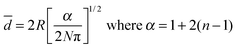
In addition to the experimental determination of the first neighbor's distances by using AFM images, the deposit of randomly distributed nanoparticles was also simulated, assuming spherical nanoparticles. In other words, we have simulated the case of an ideal system where the final position of each deposited nanoparticle is not affected by interparticle interactions. Such random deposits were generated by creating a series of random (xi,yi) coordinates using the Fortran Standard Generator of random numbers. Then, the interparticle distance distributions were extracted and finally the nearest-neighbor's distances following the same method as for the experimental case. Fig. 3 presents the experimental and simulated average first interparticle neighbor's distances as a function of the coverage percentage (down triangles and orange diamonds, respectively). The resulting curve was fitted using eqn (5). The dependence of the distance on the occupation percentage follows the expected tendency: the higher the coverage the less average distance. In order to get more insight we have represented the difference between the two curves of Fig. 3 (black line) and the corresponding differentiate (blue line) in the inset of Fig. 3. Experimental average first interparticle distance is systematically higher than the simulated average interparticle distance (for a random system) for coverages between 1.7% and 10.6%. Taking into account the error bars (Fig. 3), it can be observed that the experimental and simulated tendencies are quite similar for coverage percentage lower than 3.5%. Thus, it can be considered that nanoparticles are randomly distributed for low-density nanoparticles deposits. For coverage percentage higher than 3.5%, there is a gap between the experimental and simulated data. The sign of the difference curve, Δ, clearly indicates that the dominant interactions are repulsive and a more complex magnetic response is expected above this critical coverage. In these cases, interparticle interactions influence the final location of each nanoparticle during the deposition process and, consequently, it is not purely random, in agreement with studies of exchange-coupled systems.77–79 Simulated and experimental data present deviations at intermediate and higher surface coverages that lead to a difference of 6.5 nm in the average first neighbors distance.
 | ||
| Fig. 3 Representation of the experimental and simulated average first neighbor distance as a function of the coverage percentage. Inset corresponds to the difference between experimental and simulated curves (Δ, black line) and the Δ differentiate (δΔ, blue line). | ||
The interactions between nanoparticles are defined as a sum of the electrostatic interactions, van der Waals attractions and magnetic interactions.80 We believe that the magnetic interactions can be neglected since the nanoparticles present a superparamagnetic behavior at room temperature and there is no applied magnetic field. The steric repulsion interactions in the case of nanoparticles are associated to the deliberate coating of the nanoparticle surface: charged molecules tethered onto the particle surface.81 Obviously this is not the case for our systems that are grown under ultra high vacuum conditions. In solution, large isotropic van der Waals interactions induce the formation of spherical aggregates, in the absence of the dipolar interactions.81 The van der Waals interactions originated from the electromagnetic fluctuations due to the incessant movements of positive and negative charges within all types of atoms, molecules, and bulk materials.80 van der Waals interactions are expected to be attractive. The experimental average first neighbor's distance being always higher than the simulated one clearly indicates that the dominant interaction is repulsive and, therefore, we can consider that the van der Waals attractive interactions are negligible. The electrostatic interactions can be either attractive or repulsive and their origins are due to charge–charge interactions and induce electrical polarization of the NPs.82 As a consequence of our NPs fabrication process, 80% of the nanoparticles can present an electric charge.83 This charge can be very high due to the number of atoms in the 10 nm diameter NPs (more than 45 thousands atoms). Although the fabrication process can lead to highly charged NPs, electrostatic repulsion is only plausible provided that the NPs keep their charges for at least enough time to interact with their neighbors. Moreover, Guerrero-García et al. have studied the potential of mean force between identical charged nanoparticles in the presence of a size-asymmetric monovalent electrolyte in the case of larger magnitude of the nanoparticle charge.84 The interactions between two equal charged nanoparticles is the sum of a macroion repulsive core (Lennard-Jones potential) plus a Coulomb interaction and authors observed that core and Coulomb interactions are repulsive, over distances higher than the nanoparticle diameter. Guerrero-García et al. verify that if nanoparticles present a large enough charge, the average interaction can present a repulsive behavior over the NP diameter distance.
We cannot definitively conclude on the origin of the observed repulsive behavior, but the experimental fact cannot be neglected. Such interactions will be studied in the light of the magnetic response of the systems in order to understand the physics of the phenomenon that underlies.
(c) Magnetic properties
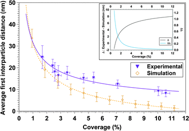
Magnetic behavior of systems made of NPs embedded in matrices depends on the properties of constituents (e.g. particle size, structure and composition) and on the interplay between magnetic anisotropy and interparticle interactions conditioned by the matrix.85 The magnetic anisotropy energy of nanoparticles has two principal contributions. On the one hand, the volume anisotropy is mainly determined by the particles crystallographic structure via the magnetocrystalline anisotropy. On the other hand, the surface anisotropy has two origins. First, as the lower coordinated atoms at the surface are in a less symmetric environment, they present enhanced magnetic anisotropy energy as compared to the bulk. This surface anisotropy is intrinsic to the particle and independent of the matrix.86,87 The second one is due to the NPs/matrix interface, namely interfacial anisotropy. For example, in the case of metallic matrices, the interfacial anisotropy is due to the spin–orbit coupling and hybridization between cluster and matrix orbitals, as already shown in Co/Pt multilayers88 or Co clusters embedded in Pt matrices.44 Another typical interface anisotropy effect is the exchange anisotropy between a ferromagnetic and an antiferromagnetic phase such as in Co–CoO core–shell nanoparticles.89 In addition, both local couplings and long-range interactions condition the magnetic response, which is consequently dependent on the magnetic size distribution, the surrounding matrix and nanoparticles/matrix interface structure. By varying the interparticle distance (i.e., the coverage percentage), the relative importance of these contributions can be tuned to a certain extent. Within this frame we discuss and interpret the presented magnetic results.The magnetic properties of Co nanoparticles inserted in the multilayered systems Si(100)/40 nm Au/CoNPs/40 nm Au and Si(100)/40 nm Au/15 nm V/CoNPs/15 nm V/40 nm Au have been measured by SQUID as a function of Co NPs density or coverage percentage. As it can be seen in Fig. 4a (Au/V/Co/V/Au system), hysteresis loops show that the majority of Co nanoparticles are superparamagnetic at room temperature. This behaviour is also observed in the Au/Co/Au system. In order to determine the nanoparticles magnetic volume, the superparamagnetic hysteresis loops have been fitted to the canonical Langevin function, considering a magnetization saturation of bulk hcp Co. In Au and V systems and for all coverages, the magnetic diameter estimated from the fits of RT cyclates using the canonical Langevin function is around 7.0 ± 0.5 nm. Therefore, nanoparticles with physical diameter of 10.3 nm should be formed by a ferromagnetic core with a 7.0 nm average diameter and a shell of around 1.6 nm width. However, as we will present later in the manuscript, our systems do not behave like canonical superparamagnets. Hence, the scaling law cannot describe the magnetic response.90 In many superparamagnetic systems a lack of agreement between experimental data and the standard superparamagnetic theory is commonly observed. Other authors have shown that in the case of systems with interparticle interactions or size distributions (i.e. systems that do not behave as ideal superparamagnets), an apparently good fit of the magnetization curve with the Langevin equation often leads to inconsistent results.91–93 In those systems, the magnetic size deduced from a Langevin function fit can be quite different when compared to direct structural measurements.94 Allia et al.93 presented apparently good Langevin fitting curves of interacting particles systems. However, those fits led to magnetic moment and particle size smaller than the real ones. Monte Carlo simulations in a Co nanoparticles system with dipolar interactions95 have clearly demonstrated that the results obtained from conventional fitting procedures are unrealistic. In conclusion, it cannot be excluded a priori that magnetic size does not increase with surface coverage.
 | ||
| Fig. 4 Normalized hysteresis loops of the Au/V/Co/V/Au system for 5.4% coverage percentage: measured at 300 K and fitted to modified Langevin function (a) and measured at 10 K following the Zero Field Cooled (ZFC) and Field Cooled (FC) procedure (b). Overlap of normalized hysteresis loops of some representative coverage percentages of Au/Co/Au (c) and Au/V/Co/V/Au systems (d) measured at 10 K following the FC procedure. | ||
The interacting superparamagnetic model (ISP) considers dipolar interaction as a perturbation of the superparamagnetic regime, which can be taken into account by adding a phenomenological temperature T* to the real temperature.90 The role of this additional temperature T* is to introduce a disorder of the magnetic moments, caused by the random dipolar field acting on each dipole, changing in direction, sign, and magnitude at a very high rate.90,96 In this way, interaction effects are taken into account, adding T* to the real temperature in the Langevin function. In order to extract the true values of magnetic moment (therefore, true magnetic volume), it is necessary to estimate T*. For a distribution of magnetic moments, the low-field susceptibility χ of the ISP system is
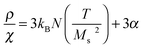 | (6) |
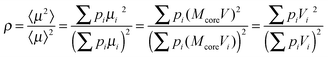 | (7) |
 as a function of T presents a linear behavior and can be obtained from the high-temperature region of the ZFC–FC curves (i.e., above blocking temperature).94 Thus, the fit was performed in the linear region of the normalized form of eqn (6),
  versus T:
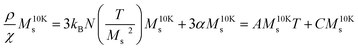 | (8) |
The definition of T* is related with eqn (8) as:
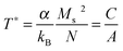 | (9) |
Including T* in the modified Langevin function, we have estimated the magnetic diameter of a set of dipolar interacting nanoparticles in the superparamagnetic regime (see example in Fig. 4a). In the case of the Au matrix, the magnetic diameter increases from 14.5 ± 0.5 nm (2.6%) to 20 ± 1 nm (10.0%) whereas, for the V system, it remains around 11–12 ± 0.5 nm for all concentrations.
As it was previously mentioned, vanadium is paramagnetic in its bulk bcc form, but can display a different magnetic state in low-dimensional systems or in contact with ferromagnetic materials. Large V induced atomic magnetic moment coupled antiferromagnetically with reduced Co atomic magnetic moment has been reported at the V/Co interface of thin films.60,61,63–67 Assuming that this antiferromagnetic coupling holds in the case of Co nanoparticles in the V matrix, exchange bias (EB) effect has been investigated in the V system. Note that such an antiferromagnetic interface is expected to contribute to the magnetization with a linear law, especially at high magnetic fields. The diamagnetic signal of the Si substrate is one order of magnitude higher than the magnetic signal of nanoparticles at high magnetic fields. An antiferromagnetic shell contribution is hardly distinguishable from the slope in the curve after subtracting the effective negative lineal contribution. Moreover, the diamagnetic signal is the sum of the diamagnetic signals from the silicon substrate and the Au matrix. Nevertheless, since this possible antiferromagnetic shell only comprises a few V atomic distances, this contribution is almost negligible when compared to the high diamagnetic signal. The effective linear contribution that is mainly due to the substrate has been systematically subtracted from our measurements in order to extract the magnetic signal from the nanoparticle layers.
The exchange bias effect has been investigated for different coverage percentages in the systems of Co nanoparticles embedded in V and Au matrices by measuring the ZFC and FC hysteresis loops after cooling the sample at 10 K under an applied field of 50 kOe. Fig. 4b reveals the absence of exchange bias in hysteresis loops for a representative sample with 5.4% coverage and Co NPs embedded in the V matrix. This result is not striking because V antiferromagnetic coupling to Co is confined at the interface with Co (i.e. it is extended over a few atomic layers).60,61 The antiparallel alignment of V atoms induced by Co atoms is always simultaneous to the ongoing Co magnetization. Hence, the antiferromagnetic volume or its anisotropy value or both factors are not enough to induce the exchange bias effect.89 The absence of EB has also been observed in the case of Co NPs embedded in the Au matrix as expected. In previous works, Co NPs were embedded in dielectric matrices (SiOx), and this matrix induced the formation of an oxide shell that was detected by the presence of EB.16,35 Fermento et al. reported that Co NPs presented a cobalt core (7–8 nm in diameter) surrounded by a cobalt oxide shell (1–2 nm thick), embedded in SiOx. The size of Co NPs in the present study is similar to that in ref. 16 and 35. On the other hand, an oxide layer would probably isolate the Co particles from the Au and V matrices and the properties of the systems would not depend on the matrix, which is in contradiction with the results presented later in the present manuscript. Moreover, we have studied the possibility of the oxidation of the NPs in the studied systems. If Co NPs are exposed to air and introduced again in the UHV system for the deposition, the hysteresis curves clearly show the EB as a consequence of the oxidation of the Co nanoparticles. In any case, the absence of EB is not a definitive proof that the Co nanoparticles are not oxidized. Hence, if our Co nanoparticles presented an oxide shell, its thickness should be lower than 1 nm16 and/or the oxide should be poorly ordered.
Representative hysteresis loops of samples with different Co percentage coverage measured at 10 K after FC in the parallel configuration are presented in Fig. 4c (Au system) and d (V system). The hysteresis loops have been normalized to the saturation magnetization (Ms) in order to facilitate the comparison. Hysteresis loops display the characteristic shape very close to the corresponding to single-domain particles with uniaxial anisotropy. Although Co NPs are polycrystalline, they are too small to sustain domain walls and are single-domain magnets.97 The shape of the hysteresis loop changes with the coverage percentage. Below 3.5% coverage, hysteresis loops exhibit narrowing/constriction that defines smaller coercive fields in both systems. These constricted loops around H = 0 can be ascribed to the existence of small nanoparticles that remain superparamagnetic down to 10 K,89 but could also come from an induced magnetic anisotropy98 whose origin remains unclear. Above this coverage, this magnetization narrowing is not observed. Based on this observation, two different contributions can be inferred depending on the coverage percentage: the first contribution would come from isolated nanoparticles, in the case of lowest coverage percentages, and the second contribution could be ascribed to nanoparticles that behave collectively,99 at coverage percentages higher than 3.5% (in agreement with Fig. 3), forming interacting magnetic states. In order to understand the magnetic response of both systems and to verify this approach, the evolution of the magnetic parameters versus the Co NPs coverage percentage for both matrices (Au and V) has been studied.
Fig. 5a displays the remanent magnetization Mr normalized to the saturation magnetization Ms as a function of the coverage percentage for Au and V systems. Independently on the matrix, both systems display an increased Mr/Ms with coverage percentage, clearly defining two different regimes below and above 3.5% surface coverage. Therefore, this coverage represents the critical coverage, dividing the magnetic behavior into two different evolutions. The Mr/Ms ratio ranges between 0.43 and 0.58 for the Au system and, in the case of the V system, between 0.46 and 0.56, describing an increase with coverage percentage. Mr/Ms ≈ 0.5 at 3.5% critical coverage corresponds to an assembly of randomly oriented macrospins non-interacting with uniaxial anisotropy compatible with a Stoner–Wohlfarth model.100 Thus, there is not an evident contradiction with Stoner–Wohlfarth model at the lowest coverage percentages.
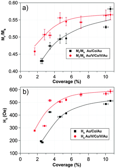 | ||
| Fig. 5 Comparative representation of remanent magnetization normalized to saturation magnetization (a) and coercive field (b) as a function of the Co coverage percentage in vanadium and gold systems. The values were extracted from the measured hysteresis loops. | ||
Coercive fields (Hc) extracted from all sets of hysteresis loops are displayed in Fig. 5b as a function of the coverage percentage for both Au and V systems. It should be noted that, in both systems, the evolution of the coercivity with coverage percentage does not reflect a single-domain to multi-domain magnetic transition or, at least, there is no evidence of a monotone decrease in the Hc curve that reflected a multi-domain transition, even though the coverage percentage reached values of 10.6% of the full monolayer.
For all coverage percentages studied, the influence of the matrix that surrounds the Co NPs is reflected in the absolute values of the magnetic parameters. The vanadium system presents higher Hc values as compared to the gold system. In other words, the vanadium matrix hardens the magnetic response of the system. One possible origin for such differences between Au and V systems could be the greater role that the interface anisotropy plays in the V system. Vanadium atoms at the nanoparticles edge can enhance this interface anisotropy through surface strains, antiferromagnetic exchange and magnetoelastic coupling.62,65 In the case of the gold matrix, this interface anisotropy would not exert a crucial influence in the Co ferromagnetic behavior of the nanoparticles due to the absence of strong coupling.49
The continuous increase of Hc in both systems could be caused by dipolar interactions originating from nanoparticles in direct contact, giving rise to the formation of clusters together with a coercivity increase (i.e., nanoparticles undergo an enhancement in the barrier against the magnetization reversal process and each NP cannot reverse independently its magnetization, leading to the appearance of a collective state).99 Henkel plots and magnetic relaxation measurements have been performed in order to demonstrate not only the presence of interparticle interactions but also their nature and relevance in the studied systems.
The magnetic relaxation data have been represented as a function of time. In Fig. 6a we display a representative example of magnetic relaxation measurements for 4.4% coverage in the V matrix. Best fits were obtained using a logarithmic decay with the time for all surface coverages in both systems. In other words, the reorientation of the magnetic moment of each nanoparticle depends on the internal magnetic field, which includes the average dipolar field from surrounding nanoparticles.101
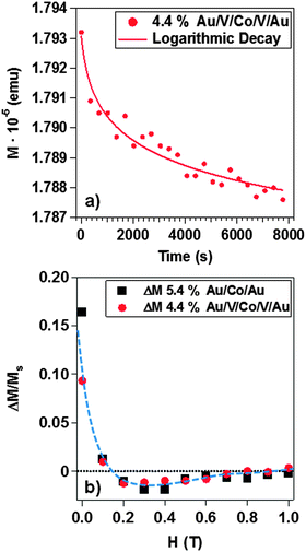 | ||
| Fig. 6 Magnetic relaxation as a function of the time for the Au/V/Co/V/Au system with 5.4% coverage of Co NPs (a). A logarithmic decay is presented. Henkel plot for 5.4% Au/Co/Au and 4.4% Au/V/Co/V/Au systems (b). | ||
Fig. 6b shows Henkel plots in both systems: 5.4% coverage in the Au matrix and 4.4% coverage, for the V system. ΔM is defined as a function of external applied magnetic field, H:
| ΔM = Md(H) − [Mr(∞) − 2Mr(H)] = Md(H) − [Ms − 2Mr(H)] | (10) |
In Fig. 7 we present the representative ZFC and FC magnetization curves measured from low (a,b), medium (c,d) and high (e,f) coverage percentage in Au and V systems. The diamagnetic contribution of the Si substrate and the Au matrix is not negligible in the magnetization versus temperature curve. The diamagnetic signal is equal to 6 × 10⁻⁶ emu at an applied magnetic field of 1500 Oe. i.e., this diamagnetic signal is one order of magnitude smaller than the magnetic signal of nanoparticles in Fig. 7. Nevertheless, this background is a small constant value independent of temperature, as the magnetization of a diamagnet is independent of temperature. Therefore, the M(T) curve shape cannot be modified by the background and the magnetization value can be hardly increased. However, background contribution is very significant when the measurement is performed with high magnetic fields. In the case of the Au/Co/Au system, the blocking temperature (TB) that is associated to the maximum of the ZFC curve and reflects the transition from the ferromagnetic to the superparamagnetic regime has been extracted from the curves. In the case of the Au/V/Co/V/Au system, the evolution of the ZFC and FC magnetization curves follows a different tendency. The large irreversibilities between ZFC and FC curves point toward the presence of disorder and magnetic frustration in the systems. Indeed, in the V system, an anomaly or a hint of it can be spotted for low and medium coverages samples at around 50 K (cf.Fig. 7b and d) in both FC and ZFC curves, and that could be interpreted as a spin or cluster-glass like transition defined with a Tg transition temperature. At low coverage (Fig. 7a and b), the transition temperatures are around 50 K in both systems (55 ± 7 K in Au and 52 ± 4 K in V). These values are in the range that is also compatible with a superparamagnetic/ferromagnetic transition reported for Co nanoparticles of similar diameter53,104–106 and might be shadowed in the Au/V/Co/V/Au system due to the presence of a spin or cluster-glass like transition. As the coverage percentage is increased, the evolution of the magnetization with temperature depends markedly on the matrix. For the V system, the Tg is almost suppressed at higher coverage (Fig. 7f) and a broadening of the curves together with a moderate displacement of the blocking temperature to higher temperature is observed. For the case of Co NPs embedded in Au, a different evolution with the coverage percentage is observed: an extremely broad peak at higher temperatures (between 175 K and 235 K) is measured, indicating a wide distribution of energy barriers in the samples. The width of this peak prevents the identification of a single blocking temperature. The temperature at which the blocking transition occurs primarily depends on particle magnetic volume. A broad maximum such as the ones shown in Fig. 7c and e may result from a wide distribution of particle magnetic sizes. A broad peak in ZFC curves is also observed when magnetic interactions occur between particles producing a collective magnetic behavior, in addition to a possible increase in the magnetic size. In ZFC curves, this magnetic size distribution is evidenced by the unblocking of the nanoparticles at different temperatures and does not contribute to the net magnetization, whereas the unblocked behavior does not affect the magnetization in the FC measurement. Such collective behavior observed in the Au system is not observed in the V system, where the matrix isolates magnetically the Co NPs and hinders possible collective behaviors. The observed differences in the magnetic response highlight the importance of the surrounding matrix of NPs.
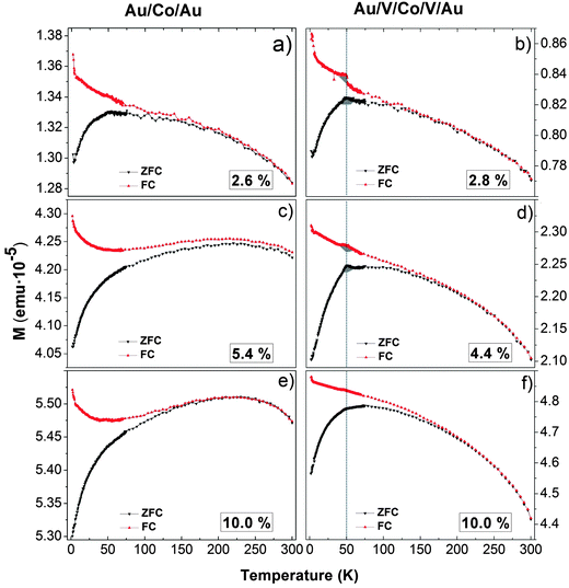 | ||
| Fig. 7 Zero Field Cooled (ZFC) and FC evolution of the magnetization as a function of temperature for the Au system with 2.6% (a), 5.4% (c) and 10.0% (e) Co percentages of a monolayer and the V system with 2.8% (b), 4.4% (d) and 10.0% (e) Co percentages of a monolayer. | ||
Fig. 8 represents the evolution of the blocking temperatures extracted from magnetization vs. temperature curves (from Fig. 7). There are several standard methods to estimate the blocking temperature, TB. In the majority of the literature, the blocking temperature has been extracted as the maximum of d(MFC − MZFC)/dT curves as a function of the temperature. However, with this procedure, the estimated TB leads to a unique average blocking temperature of the system.107 In our case this method does not allow a clear determination of a unique blocking temperature. We have rather represented Log(MFC − MZFC) as a function of the temperature for M vs. T of Fig. 7 for Au and V systems. For the Au matrix case, we can distinguish two regions that are fitted with a 2nd order polynomial function. Each minimum of the curve, obtained by the fitting differentiate, defines a blocking temperature (Fig. 8). For the V matrix case, only one region can be distinguished, which leads to only one blocking temperature. Fig. 8 has been presented in order to highlight the different magnetic behaviors between the systems with V and Au matrices. In the case of the Au matrix, TB1 (red circles) is the blocking temperature associated to the magnetic response of 10 nm physically isolated NPs. TB2 (open squares) corresponds to the assembly of NPs that have agglomerated and therefore display a bigger magnetic volume as a result of interparticle dipolar interactions. The huge deviations of the blocking temperatures reveal different magnetic responses of both systems.
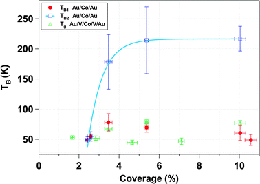 | ||
| Fig. 8 Transition temperatures of the Au/Co/Au and Au/V/Co/V/Au systems extracted from the magnetization vs. temperature curves (Fig. 6) as a function of coverage percentage. In the case of Co nanoparticles embedded in the Au matrix, there are two blocking temperatures. TB1 corresponds to the blocking temperature for isolated nanoparticles. TB2 is the blocking temperature associated to nanoparticles’ population acting collectively. | ||
The possible higher interface anisotropy in the case of the V system in comparison with the Au system does not explain the higher TB in the Au system for coverage higher than 3.5%. These tendencies are in contradiction with other previous works.33,108 Tamion et al. and Rohart et al. reported that the higher the effective anisotropy is the higher the values of the characteristic magnetic parameters are. Moreover, Domingo et al. and Skumryev et al. reported that in the case of Co–CoO exchange biased systems, the exchange anisotropy between ferromagnetic core and antiferromagnetic shell induced a shift of the superparamagnetic limit to higher temperatures and an increased coercivity.54,109 Therefore, in our cases the difference in TB between the two systems at coverages higher than 3.5% cannot be explained by a rise of the interface anisotropy in the V system.
As surface coverage increases, the number of interacting Co nanoparticles rises. When the percentage is higher than 3.5%, magnetic clusters of interacting nanoparticles start to be relevant and give rise to the modification of the magnetic properties. The direct exchange interaction can be negligible when the average edge-to-edge distance between neighbor nanoparticles is higher than 10 nm and in that case the magnetic properties of the nanoparticles are determined by the energy field dipole and magnetic anisotropy energies.101 However, at 10.6% surface coverage, 48% of the first neighbor's distance is lower than 10 nm, where direct exchange interactions can exist (Fig. 2). In addition, ΔM measurements have evidenced the presence of exchange interactions (ΔM > 0 at several external applied magnetic fields) although dipolar interactions are dominant (ΔM < 0, Fig. 6b). The increase in the TB with particle coverage has been reported and attributed to dipolar interactions between particles.110–116 At high coverage percentages, strong dipolar fields of coherent clusters are formed, favored by the increase of direct exchange interaction117 that results from reduced interparticle distances. These dipolar fields are likely to introduce an extra anisotropy in the system and induce the increase of TB254,118 whereas TB1 ranges between 49 ± 9 K and 78 ± 14 K. Interactions are able to overcome the thermal decay and shift the superparamagnetic transition to higher temperature. This is the case for the Au matrix where the dipolar interactions influence the magnetic behavior of the Au system.54 In addition, the presence of a magnetic size distribution increases the maximum broadening of ZFC curves and explains the magnetic response displayed in Fig. 7c and e. Therefore, the Au matrix does not screen the magnetic interactions between nanoparticles, leading to a collective behavior at higher coverage percentages in accordance to the relaxation time measurements and Henkel plots (Fig. 6). Moreover, the FC magnetization curve is distorted, experiencing a bowing to lower values below the blocking temperature, which is a fingerprint of a contribution of collective interactions between nanoparticles.119,120
In the vanadium case, the absence of collective behavior between nanoparticles is reflected in the nearly constant value of Tg with coverage and can be explained taking into account a spin glassy like behavior at the interface. This behavior may be caused by the combination of two factors. The first one takes into account the difference between the magnetic behavior of the particle surface and that corresponding to the core, due to the lower coordination number of the outermost atoms. The second factor is the antiferromagnetic coupling between V and Co at the Co–V interface together with the V induced magnetic moment and reduced Co atomic magnetic moment.60,61,63–67 The reduced coordination between surface spins that induces spin canting and the presence of antiferromagnetic order are compatible with a spin or cluster-glass like behavior at the surface.30,89,121,122 In other words, the presence of short-range correlated areas that remain limited in size and noncollinear ordering of magnetic moments define the magnetic state at the Co–V interface. A canonical spin glass could be defined as a magnetic system with a combination of ferromagnetic and antiferromagnetic interactions, characterized by a cooperative and random freezing of spins at a transition temperature, Tf. Below Tf a high irreversibility develops. The main contributions are mixed interactions, competition among them (frustration) and disorder. The formation of a spin glass like surface layer is the most reliable explanation for the experimental evidence presented in our work: (i) The anomaly or sharp maximum around 50 K (colored zone in grey in Fig. 7b and d), hardly observed in the gold system. Similar behavior has been described in other nanoparticles systems123,124 in which, by decreasing temperature, surface-spin fluctuations slow down and short-range interactions between surface spins develop, resulting in a progressive formation of regions of magnetically correlated spins of growing size that finally give rise to a frozen, disordered surface-spin state (likely a cluster-glass state). (ii) The observed difference in the values of TB1 and Tg in Fig. 8 at coverage percentages equal to or higher than 3.5%. (iii) The antiferromagnetic polarization between V and Co at an interface with high structural disorder. This polarization was demonstrated in thin films.60,61 On the other hand, it is known that surface effects result basically from symmetry breaking of the lattice, which leads to site-specific, generally unidirectional, surface anisotropy, and from broken exchange bonds, which lead to surface spin misalignment with respect to the ordered core spins and to surface spin disorder and frustration, for small enough particle sizes, as reported for ferrimagnetic particles; see ref. 125 and 126 and references therein. In this context, we show here that the disorder at the Co/V interface, when it is located at a nanoparticle surface, can induce the formation of a spin glass like stage. The Co–V disordered magnetic interface screens the magnetic interactions between nanoparticles, preventing a collective response of the system. This also explains the higher magnetic hardening in comparison with the Au system (Fig. 5b). Finally, the observed difference in the values of TB1 and Tg in Fig. 8 at coverage percentages equal to or higher than 3.5% is compatible with the tendency of magnetic sizes deduced from the fits with modified Langevin function with T* in both systems.
IV. Conclusions
We have analyzed the magnetic response of well-characterized Co nanoparticles of 10.3 nm average diameter embedded in Au and V matrices and with different coverage percentage of a monolayer (from 1.7 to 10.6%). In both Au and V systems, 3.5% represents the critical coverage percentage at which there is a change in the tendency of the magnetic parameters extracted from the hysteresis curves, TB and the evolution of the average interparticle distance of the studied systems. Below this coverage threshold, (i) nanoparticles are randomly distributed and (ii) the interparticle distance is such that Co nanoparticles present the magnetic response of isolated nanoparticles. Above this critical coverage, interparticle interactions start playing an important role in the final magnetic response of the system in the Au/Co/Au case. The final location of each NP during the deposition is influenced by the already deposited NPs, which results in a distribution that is not totally random. The system morphology evolves towards the formation of coherent clusters, associated to the nanoparticles agglomeration that has been attributed to interparticle interactions. Henkel plots and magnetic relaxation measurements have demonstrated not only the presence of interparticle interactions but also their dipolar nature and relevance in the studied systems. Moreover, independently of the magnetic volume studied in this work, the single-domain magnetic nature seems to be maintained.As the surface coverage increases above the critical value, changes in the magnetic properties are observed that also depend on the matrix element. In the Au system, there is a size distribution that results in a competition between isolated nanoparticles and nanoparticles that act collectively. Its magnetic response is influenced by dipolar interparticle interactions, leading to two blocking temperatures.
On the other hand, the V matrix has a larger influence on the final magnetic response of the system. The different magnetic behavior between core and non-ferromagnetic shell of the nanoparticles, in addition to antiferromagnetic coupling between V and Co surface spins, makes the system more complex and more difficult to be reversed by the magnetic field. This adds more magnetic frustration in the V-system enhancing the glassy behavior that appears through the anomaly detected at around 50 K. This magnetic disorder would prevent the dipolar interaction between the ferromagnetic cores. We observed a unique nearly constant value of Tg. Hence, the V system presents higher Hc with regard to the Au system.
Acknowledgements
TEM work has been performed at LABMET laboratory associated to the Red de Laboratorios of Comunidad de Madrid. Work was supported by the Spanish Ministerio de Economía y Competitividad under projects MAT2011-29194-C02-02, MAT2011-27470-C02-02, MAT-2007-66181, MAT2008-06765-C02, MAT2008-06517-C02-01, CSD2007-00041 (NANOSELECT), CSD2008-00023 (FUNCOAT), CSD2009-00013, CSD2007-00010, FIS2008-06249 (Grupo Consolidado), CAM grant S2009/MAT-1726, Santander-UCM grant GR35/10-A-910571 and European Commission NMP3-SL-2008-214107. M.R. acknowledges the FPI grant from the Spanish Ministerio de Economía y Competitividad.References
- A. Biswas, H. Eilers, F. Hidden Jr., O. C. Aktas and C. V. S. Kiran, Appl. Phys. Lett., 2006, 88, 13103 CrossRef.
- A. Bouñinos, A. Simopoulos, D. Petridis, H. Okumura and G. Hadjipanays, Adv. Mater., 2001, 13, 289 CrossRef.
- Y. Lu, G. L. Liu and L. P. Lee, Nano Lett., 2005, 5, 5 CrossRef CAS.
- B. Rellinghaus, S. Stappet, M. Acet and E. F. Wassermann, J. Magn. Magn. Mater., 2003, 266, 142 CrossRef CAS.
- S. Sun, C. B. Murray, D. Weller, L. Folks and A. Moser, Science, 2000, 287, 1989 CrossRef CAS.
- J. van Ek and D. Weller, in The Physics of Ultrahigh-Density Magnetic Recording, ed. M. Plumer, J. van Ek and D. Weller, Springer Series in Surface Sciences, Berlin, 2001, vol. 41 Search PubMed.
- C. Sun, J. S. H. Lee and M. Zhang, Adv. Drug Deliv. Rev., 2008, 60, 1252 CrossRef CAS.
- L. M. Parkes, R. Hodgson, L. T. Lu, L. D. Tung, I. Robinson, D. G. Ferning and N. T. K. Thanh, Contrast Media Mol. Imaging, 2008, 3, 150 CrossRef CAS.
- M. T. Nguyen and A. F. Diaz, Adv. Mater., 1994, 6, 858 CrossRef.
- C. Binns, M. J. Maher, Q. A. Pankhurst, D. Kechrakos and K. N. Trohidou, Phys. Rev. B: Condens. Matter Mater. Phys., 2002, 66, 184413 CrossRef.
- Y. A. Koksharov, in Magnetic Nanoparticles, ed. S. P. Gubin, Wiley-VCH, Weinheim, 2009 Search PubMed.
- F. Tournus, A. Tamion, N. Blanc, A. Hannour, L. Bardotti, B. Prével, P. Ohresser, E. Bonet, T. Epicier and V. Dupuis, Phys. Rev. B: Condens. Matter Mater. Phys., 2008, 77, 144411 CrossRef.
- O. Iglesias and A. Labarta, Physica B, 2004, 343, 2862 CrossRef.
- Y. Huttel, E. Navarro, N. D. Telling, G. van der Laan, F. Pigazo, F. J. Palomares, C. Quintana, E. Roman, G. Armelles and A. Cebollada, Phys. Rev. B: Condens. Matter Mater. Phys., 2008, 78, 104403 CrossRef.
- S. H. Baker, M. Roy, S. J. Gurman, S. Louch, A. Bleloch and C. Binns, J. Phys.: Condens. Matter, 2004, 16, 7813 CrossRef CAS.
- R. Fermento, J. B. González-Díaz, A. Cebollada, G. Armelles, M. Díaz, L. Martínez, E. Román, Y. Huttel and C. Ballesteros, J. Nanopart. Res., 2011, 13, 2653 CrossRef CAS.
- B. K. Canfield, S. Kujala, K. Laiho, K. Jefimovs, T. Vallius, J. Turunen and M. Kauranen, J. Nonlinear Opt. Phys., 2006, 15, 43 CrossRef CAS.
- K. Delgado, R. Quijada, R. Palma and H. Palza, Lett. Appl. Microbiol., 2011, 53, 50 CrossRef CAS.
- M. Torrell, R. Kabir, L. Cunha, M. I. Vasilevskiy, F. Vaz, A. Cavaleiro, E. Alves and N. P. Barradas, J. Appl. Phys., 2011, 109, 074310 CrossRef.
- R. F. Ziolo, E. P. Giannelis, B. A. Weinstein, M. P. O'Horo, B. N. Ganguly, V. Mehrotra, M. W. Russell and D. R. Huffman, Science, 1992, 257, 219 CAS.
- F. Choueikani, F. Royer, D. Jamon, A. Siblini, J. J. Rousseau, S. Neveu and J. Charara, Appl. Phys. Lett., 2009, 94, 051113 CrossRef.
- S. Ohnuma, H. Fujimori, S. Mitani and T. Masumoto, J. Appl. Phys., 1996, 79, 5130 CrossRef CAS.
- Q. Yan, A. Purkayastha, A. P. Singh, H. Li, A. Li, R. V. Ramanujan and G. Ramanath, Nanotechnology, 2009, 20, 025609 CrossRef CAS.
- A. N. Lagarkov and K. N. Rozanov, J. Magn. Magn. Mater., 2009, 321, 2082 CrossRef CAS.
- H. T. Beyene, V. S. K. Chakravadhanula, C. Hanisch, M. Elbahri, T. Strunskus, V. Zaporojtchenko, L. Kienle and F. Faupel, J. Mater. Sci., 2010, 45, 5865 CrossRef CAS.
- H. Biederman, Surf. Coat. Technol., 2011, 205, S10 CrossRef CAS.
- A. Perez, P. Mélinon, V. Dupuis, L. Bardotti, B. Masenelli, F. Tournus, B. Prével, J. Tuaillon-Combes, E. Bernstein, A. Tamion, N. Blanc, D. Taïnoff, O. Boisron, G. Guiraud, M. Broyer, M. Pellarin, N. Del Fatti, F. Vallée, E. Cottancin, J. Lermé, J. L. Vialle, C. Bonnet, P. Maioli, A. Crut, C. Clavier, J. L. Rousset and F. Morfin, Int. J. Nanotechnol., 2010, 7, 523 CrossRef CAS.
- K. Wegner, P. Piseri, H. Vahedi Tafreshi and P. Milani, J. Phys. D: Appl. Phys., 2006, 39, R439 CrossRef CAS.
- F. Parent, J. Tuaillon, L. B. Stern, V. Dupuis, B. Prevel, A. Perez, P. Melinon, G. Guiraud, R. Morel, A. Barthélémy and A. Fert, Phys. Rev. B: Condens. Matter Mater. Phys., 1997, 55, 3683 CrossRef CAS.
- Y. Qiang, R. F. Sabiryanov, S. S. Jaswal, Y. Liu, H. Haberland and D. J. Sellmyer, Phys. Rev. B: Condens. Matter Mater. Phys., 2002, 66, 064404 CrossRef.
- Gail N. Iles, S. H. Baker, S. C. Thornton and C. Binns, J. Appl. Phys., 2009, 105, 024306 CrossRef.
- J. A. De Toro, J. P. Andrés, J. A. González, P. Muñiz and J. M. Riveiro, Nanotechnology, 2009, 20, 085710 CrossRef CAS.
- A. Tamion, C. Raufast, M. Hillenkamp, E. Bonet, J. Jouanguy, B. Canut, E. Bernstein, O. Boisron, W. Wernsdorfer and V. Dupuis, Phys. Rev. B: Condens. Matter Mater. Phys., 2010, 81, 144403 CrossRef.
- B. Gojdka, V. Hrkac, T. Strunskus, V. Zaporojtchenko, L. Kienle and F. Faupel, Nanotechnology, 2011, 22, 465704 CrossRef CAS.
- M. Díaz, L. Martínez, M. M. Ruano, P. D. Llamosa, E. Román, M. García-Hernandez, C. Ballesteros, R. Fermento, A. Cebollada, G. Armelles and Y. Huttel, J. Nanopart. Res., 2011, 13, 5321 CrossRef.
- B. Gojdka, V. Zaporojtchenko, V. Hrkac, J. Xiong, L. Kienle, T. Strunskus and F. Faupel, Appl. Phys. Lett., 2012, 100, 133104 CrossRef.
- J. Bansmann, S. H. Baker, C. Binns, J. A. Blackman, J.-P. Bucher, J. Dorantes-Dávila, V. Dupuis, L. Favre, D. Kechrakos, A. Kleibert, K.-H. Meiwes-Broer, G. M. Pastor, A. Perez, O. Toulemonde, K. N. Trohidou, J. Tuaillon and Y. Xie, Surf. Sci. Rep., 2005, 56, 189 CrossRef CAS.
- C. Binns, K. N. Trohidou, J. Bansmann, S. H. Baker, J. A. Blackman, J.-P. Bucher, D. Kechrakos, A. Kleibert, S. Louch, K.-H. Meiwes-Broer, G. M. Pastor, A. Perez and Y. Xie, J. Phys. D: Appl. Phys., 2005, 38, R357 CrossRef CAS.
- A. Biswas, Z. Marton, J. Kanzow, J. Kruse, V. Zaporojtchenko, F. Faupel and T. Strunskus, Nano Lett., 2003, 3, 69 CrossRef CAS.
- J. Sánchez-Marcos, M. A. Laguna-Marco, R. Martínez-Morillas, E. Céspedes, F. Jiménez-Villacorta, N. Menéndez and C. Prieto, J. Phys.: Condens. Matter, 2011, 23, 476003 CrossRef.
- J. Bai and J.-P. Wang, Appl. Phys. Lett., 2005, 87, 152502 CrossRef.
- B. Balasubramanian, R. Skomski, X. Z. Li, S. R. Valloppilly, J. E. Shield, G. C. Hadjipanayis and D. J. Sellmyer, Nano Lett., 2011, 11, 1747 CrossRef CAS.
- L. Martínez, M. Díaz, E. Román, M. Ruano, D. Llamosa P. and Y. Huttel, Langmuir, 2012, 28, 11241 CrossRef.
- M. Jamet, M. Négrier, V. Dupuis, J. Tuaillon-Combees, P. Mélinon, A. Pérez, W. Wernsdorfer, B. Barbara and B. Baguenard, J. Magn. Magn. Mater., 2001, 237, 293 CrossRef CAS.
- P. Jonsson and P. Nordblad, Phys. Rev. B: Condens. Matter Mater. Phys., 2000, 62, 1466 CrossRef CAS.
- J. M. D. Coey, Phys. Rev. Lett., 1971, 27, 1140 CrossRef CAS.
- R. H. Kodama, S. A. Makhlouf and A. E. Berkowitz, Phys. Rev. Lett., 1997, 79, 1393 CrossRef CAS.
- O. Iglesias and A. Labarta, Phys. Rev. B: Condens. Matter Mater. Phys., 2001, 63, 184416 CrossRef.
- F. Wilhelm, M. Angelakeris, N. Jaouen, P. Poulopoulos, E. Th. Papaioannou, Ch. Mueller, P. Fumagalli, A. Rogalev and N. K. Flevaris, Phys. Rev. Lett., 2004, 69, 220404R Search PubMed.
- S. E. Weber, B. K. Rao, P. Jena, V. S. Stepanyuk, W. Hergert, K. Wildberger, R. Zeller and P. H. Dederichs, J. Phys.: Condens. Matter, 1997, 9, 10739 CrossRef CAS.
- I. Galanakis, P. M. Oppeneer, P. Ravindran, L. Nordström, P. James, M. Alouani, H. Dreysse and O. Eriksson, Phys. Rev. B: Condens. Matter Mater. Phys., 2001, 63, 172405 CrossRef.
- M. Jamet, V. Dupuis, P. Mélinon, G. Guiraud, A. Pérez, W. Wernsdorfer, A. Traverse and B. Baguenard, Phys. Rev. B: Condens. Matter Mater. Phys., 2000, 62, 493 CrossRef CAS.
- J. Hormes, H. Modrow, H. Bönnemann and C. S. S. R. Kumnar, J. Appl. Phys., 2005, 97, 10R102 CrossRef.
- N. Domingo, A. M. Testa, D. Fiorani, C. Binns, S. Baker and J. Tejada, J. Magn. Magn. Mater., 2007, 316, 155 CrossRef CAS.
- M. Hou, M. E. Azzaoui, H. Pattyn, J. Verheyden, G. Koops and G. Zhang, Phys. Rev. B: Condens. Matter Mater. Phys., 2000, 62, 5117 CrossRef CAS.
- L. Driouch, R. Krishnan, M. Porte, K. V. Rao and M. Tessier, J. Appl. Phys., 1997, 81, 3806 CrossRef.
- T. Thomson, P. C. Riedi and R. Krishnan, J. Appl. Phys., 2000, 87, 6594 CrossRef CAS.
- R. Krishnan, T. Catinaud, M. Seddat, M. Porte and M. Tessier, J. Magn. Magn. Mater., 1996, 159, 175 CrossRef CAS.
- M. A. Leyva-Lucero, R. E. Félix-Medina, S. Meza-Aguilar and C. Demangeat, Surf. Sci., 2011, 605, 1738 CrossRef CAS.
- Y. Huttel, G. van der Laan, T. K. Johal, N. D. Telling and P. Bencok, Phys. Rev. B: Condens. Matter Mater. Phys., 2003, 68, 174405 CrossRef.
- Y. Huttel, C. Clavero, G. van der Laan, P. Bencok, T. K. Johal, J. S. Claydon, G. Armelles and A. Cebollada, Phys. Rev. B: Condens. Matter Mater. Phys., 2008, 77, 064411 CrossRef.
- J. F. Calleja, Y. Huttel, M. C. Contreras, E. Navarro, B. Presa, R. Matarranz and A. Cebollada, J. Appl. Phys., 2006, 100, 053917 CrossRef.
- Jisang Hong, Surf. Sci., 2006, 600, 2323 CrossRef CAS.
- Jisang Hong, J. Magn. Magn. Mater., 2006, 303, 191 CrossRef CAS.
- T. A. Carillo-Cázares, S. Meza-Aguilar and C. Demangeat, J. Magn. Magn. Mater., 2005, 290–291, 110 CrossRef.
- T. A. Carillo-Cázares, S. Meza-Aguilar and C. Demangeat, Eur. Phys. J. B, 2005, 48, 249 CrossRef.
- T. A. Carillo-Cázares, S. Meza-Aguilar and C. Demangeat, Solid State Commun., 2007, 144, 94 CrossRef.
- Oxford Applied Research, http://www.oaresearch.co.uk.
- http://www.nanotec.es .
- I. Horcas, R. Fernandez, J. M. Gómez-Rodriguez, J. Colchero, J. Gómez-Herrero and A. M. Baró, Rev. Sci. Instrum., 2007, 78, 013705 CrossRef CAS.
- http://rsbweb.nih.gov/ij .
- J. García-Otero, M. Porto and J. Rivas, J. Appl. Phys., 2000, 87, 7376 CrossRef.
- M. Munz, J.-H. Kim, O. Krause and D. Roy, Surf. Interface Anal., 2011, 43, 1382 CrossRef CAS.
- R. Morel, A. Brenac, P. Bayle-Guillemaud, C. Portemont, T. Deutsch and L. Notin, J. Magn. Magn. Mater., 2007, 308, 296 CrossRef CAS.
- S. Srinivasa and M. Haenggi, IEEE. T. Veh. Technol., 2010, 59, 940 CrossRef.
- F. Tournus, J. Nanopart. Res., 2011, 13, 5211 CrossRef CAS.
- K. W. Edmonds, C. Binns, S. H. Baker S. C. Thornton and P. Finetti, J. Appl. Phys., 2000, 88, 3414 CrossRef CAS.
- L. Thomas, J. Tuaillon, J. P. Perez, V. Dupuis and B. Barbara, J. Magn. Magn. Mater., 1995, 145, 74 CrossRef.
- D. Kechrakos and K. N. Trohidou, Phys. Rev. B: Condens. Matter Mater. Phys., 1998, 58, 12169 CrossRef CAS.
- K. J. M. Bishop, C. E. Wilmer, S. Soh and B. A. Grzybowski, Small, 2009, 5, 1600 CrossRef CAS.
- Y. Lalatonne, J. Richardi and M. P. Pileni, Nat. Mater., 2004, 3, 121 CrossRef CAS.
- D. A. Walker, B. Kowalczyk, M. O. de la Cruz and B. A. Grzybowski, Nanoscale, 2011, 3, 1316 RSC.
- H. Haberland, M. Karrais, M. Mall and Z. Phys. D Atoms, Mol. Clusters, 1991, 20, 413 CrossRef CAS.
- G. I. Guerrero-García, P. González-Mozuelos and M. Olvera de la Cruz, J. Chem. Phys., 2011, 135, 16705 Search PubMed.
- G. M. Pastor and P. J. Jensen, Phys. Rev. B: Condens. Matter Mater. Phys., 2008, 78, 134419 CrossRef.
- M. Jamet, W. Wernsdorfer, C. Thirion, V. Dupuis, P. Mélinon, A. Pérez and D. Mailly, Phys. Rev. B: Condens. Matter Mater. Phys., 2004, 69, 024401 CrossRef.
- M. Jamet, W. Wernsdorfer, C. Thirion, D. Mailly, V. Dupuis, P. Mélinon and A. Pérez, Phys. Rev. Lett., 2001, 86, 4676 CrossRef CAS.
- N. Nakajima, T. Koide, T. Shidara, H. Miyauchi, H. Fukutani, A. Fujimori, K. Iio, T. Katayama, M. Nývlt and Y. Suzuki, Phys. Rev. Lett., 1998, 81, 5229 CrossRef CAS.
- J. Nogués, V. Skumryev, J. Sort, S. Stoyanov and D. Givord, Phys. Rev. Lett., 2006, 97, 157203 CrossRef.
- M. Knobel, W. C. Nunes, L. M. Socolovsky, E. De Biasi, J. M. Vargas and J. C. Denardin, J. Nanosci. Nanotechnol., 2008, 8, 2836 CAS.
- H. Mamiya, I. Nakatani, T. Furubayashi and M. Ohnuma, Trans. Magn. Soc. Japan, 2002, 2, 36 CrossRef CAS.
- A. L. Brandl, J. C. Denardin, L. M. Socolovsky, M. Knobel and P. Allia, J. Magn. Magn. Mater., 2004, 272–276, 1526 CrossRef CAS.
- P. Allia, M. Coisson, P. Tiberto, F. Vinai, M. Knobel, M. A. Nova and W. C. Nunes, Phys. Rev. B: Condens. Matter Mater. Phys., 2001, 64, 144420 CrossRef.
- J. M. Vargas, W. C. Nunes, L. M. Socolovsky, M. Knobel and D. Zanchet, Phys. Rev. B: Condens. Matter Mater. Phys., 2005, 72, 184428 CrossRef.
- M. El-Hilo, R. W. Chantrell and K. O'Grady, J. Appl. Phys., 1998, 84, 5114 CrossRef CAS.
- P. Allia, P. Tiberto and F. Vinai, J. Appl. Phys., 1997, 81, 4599 CrossRef CAS.
- C. A. Moina, L. de Oliviera-Versic and M. Vazdar, Mater. Lett., 2004, 58, 3518 CrossRef CAS.
- B. D. Cullity, Introduction to magnetic materials, Addison-Wesley publishing, 1972 Search PubMed.
- V. F. Puntes, P. Gorostiza, D. M. Aruguete, N. G. Bastus and A. P. Alivisatos, Nat. Mater., 2004, 3, 263 CrossRef CAS.
- E. C. Stoner and E. P. Wohlfarth, Phys. Sci., 1948, 240, 554 Search PubMed.
- R. Prozorov, Y. Yeshurun, T. Prozorov and A. Gedanken, Phys. Rev. B: Condens. Matter Mater. Phys., 1999, 59, 6956 CrossRef CAS.
- W. C. Numes, F. Cebollada, M. Knobel and D. Zanchet, J. Appl. Phys., 2006, 99, 08N705 CrossRef.
- Q. Chen, B. M. Ma, B. Lu, M. Q. Huang and D. E. Laughlin, J. Appl. Phys., 1999, 85, 5917 CrossRef CAS.
- U. Wiedwald, M. Spasova, M. Farle, M. Hilgendorff and M. Giersig, J. Vac. Sci. Technol. A, 2001, 19, 1773 CAS.
- P. M. Paulus, H. Bönnemann, A. M. van der Kraan, F. Luis, J. Sinzig and L. J. de Jongh, Eur. Phys. J. D, 1999, 9, 501 CrossRef CAS.
- V. F. Puntes and K. M. Krishnan, IEEE Trans. Magn., 2000, 37, 2210 CrossRef.
- M. Knobel, L. M. Socolovsky and J. M. Vargas, Rev. Mex. Fís. E, 2004, 50, 8 CAS.
- S. Rohart, C. Raufast, L. Favre, E. Bernstein, E. Bonet and V. Dupuis, Phys. Rev. B: Condens. Matter Mater. Phys., 2006, 74, 104408 CrossRef.
- V. Skumryev, S. Stoyanov, Y. Zhang, G. Hadjipanayis, D. Givord and J. Nogués, Nature, 2003, 423, 850 CrossRef CAS.
- J. L. Dormann, D. Fiorani and E. Tronc, Adv. Chem. Phys., 1997, 98, 283 CrossRef CAS.
- R. W. Chantrell, in Magnetic Hysteresis in Novel Magnetic Materials, ed. G. C. Hadjipanayis, Kluwer, Dordrecht, 1997, vol. 338, NATO Advanced Study Institute, Series E: Applied Sciences Search PubMed.
- R. W. Chantrell, M. El-Hilo and K. O'Grady, IEEE Trans. Magn., 1991, 27, 3570 CrossRef.
- M. El-Hilo, K. O'Grady and R. W. Chantrell, J. Magn. Magn. Mater., 1992, 114, 295 CrossRef CAS.
- W. Luo, S. R. Nagel, T. F. Rosenbaum and R. E. Rosensweig, Phys. Rev. Lett., 1991, 67, 2721 CrossRef CAS.
- S. Mørup and E. Tronc, Phys. Rev. Lett., 1994, 72, 3278 CrossRef.
- S. Mørup, F. Bodker, P. V. Hendriksen and S. Linderoth, Phys. Rev. B: Condens. Matter Mater. Phys., 1995, 52, 287 CrossRef.
- D. Kechrakos and K. N. Trohidou, J. Magn. Magn. Mater., 2003, 262, 107 CrossRef CAS.
- D. Kechrakos and K. N. Trohidou, Appl. Surf. Sci., 2004, 226, 261 CrossRef CAS.
- J. Denardin, A. Brandl, M. Knobel, P. Panissod, a. Pakhomov, H. Liu and X. Zhang, Phys. Rev. B: Condens. Matter Mater. Phys., 2002, 65, 064422 CrossRef.
- P. Guardia, R. Di Corato, L. Lartigue, C. Wilhelm, A. Espinosa, M. Garcia-Hernandez, F. Gazeau, L. Manna and T. Pellegrino, ACS Nano, 2012, 6, 3080 CrossRef CAS.
- D. L. Peng, K. Sumiyama, T. Hihara, S. Yamamuro and T. J. Konno, Phys. Rev. B: Condens. Matter Mater. Phys., 2000, 61, 3103 CrossRef CAS.
- S. A. Koch, G. Palasantzas, T. Vystavel and J. Th. M. De Hosson, Phys. Rev. B: Condens. Matter Mater. Phys., 2005, 71, 085410 CrossRef.
- E. De Biasi, R. D. Zysler, C. A. Ramos, H. Romero and D. Fiorani, Phys. Rev. B: Condens. Matter Mater. Phys., 2005, 71, 104408 CrossRef.
- E. De Biasi, C. A. Ramos, R. D. Zysler and H. Romero, Phys. Rev. B: Condens. Matter Mater. Phys., 2002, 65, 144416 CrossRef.
- R. H. Kodama, A. E. Berkovitz, E. J. Mc Niff, Jr. and S. Foner, Phys. Rev. Lett., 1996, 77, 394 CrossRef CAS.
- R. H. Kodama and A. E. Berkovitz, Phys. Rev. B: Condens. Matter Mater. Phys., 1999, 59, 6321 CrossRef CAS.
| This journal is © the Owner Societies 2013 |