The direct synthesis of pure zeolite-A using ‘virgin’ Kaolin
Stuart M.
Holmes
*,
Abdulaziz A.
Alomair
and
Abdul S.
Kovo
School of Chemical Engineering and Analytical Science, The University of Manchester, Sackville Street, Manchester, M13 9LP, UK. E-mail: stuart.holmes@manchester.ac.uk; Fax: +44 (0)161 200 4399; Tel: +44 (0)161 200 4376
First published on 28th September 2012
Abstract
Here we demonstrate the conversion of a Nigerian Kaolin, straight from the source without any form of pre-treatment, directly into pure zeolite-A. The method involves a rapid and low temperature meta-kaolinization step followed by chemical conversion directly into pure zeolite-A. The synthesis step acts as the purification step removing the 80% quartz impurity simultaneously with zeolite growth. The whole process is designed to be both economical and straightforward to facilitate commercialisation.
Introduction
Zeolites are microporous alumino-silicates which are effective in a range of processes including the fluid catalytic cracking of crude oil, molecular sieving separations of gas and liquid phase molecules and ion removal from waste water streams with the additional benefit of vitrification to encapsulate particularly hazardous nuclei.Zeolite A has seen particular interest as an ion-exchange media as it has the lowest Si/Al ratio of any zeolite and hence the largest number of active sites for ion-exchange. As a result, it has been heavily used in the detergent industry as a component in washing powder to remove calcium ions.
Numerous research groups have looked at various precursors to zeolite synthesis in an attempt to reduce the cost of zeolite production. Fly-ash,1 lithium slag,2 rice husk,3 diatomite,4 illite5 and other layered silicates/clays6,7 have all shown significant potential as zeolite precursors with the clays such as kaolin being successfully transformed in to a range of zeolites.8–10
There are numerous conventional routes to zeolite A which use pure chemical precursors such as sodium aluminate, pure aluminium powder, aluminium wire as the aluminium source and sodium meta silicate, fumed silica, colloidal silica as the silica source.
The most significant barriers to commercialisation for clay precursors have been the energy and time intensive activation of the clays to make them chemically reactive coupled with the difficulty of removal of quartz and other dense phase, un-reactive, impurities from the clay which contaminate the final product.
In a previous study we demonstrated that the activity can be achieved at significantly lower temperatures and in a much shorter time than previously reported;10 sufficiently quickly that a continuous process could be envisaged. In addition, we have shown that kaolin containing a significant quartz impurity can be converted into a pure zeolite.8
In this paper we take the next logical step in which we take kaolin directly form the source (the sample was collected directly from the Ahoko kaolin deposit, a 39 hectare mine, in Kogi state, Nigeria) and rapidly activate it followed by conversion into pure zeolite A without the labour intensive settling and/or centrifugation necessary to achieve the quartz levels in commercially available kaolin.
By using a similar approach to our previous work we have separated the synthesis gel from seeds of the zeolite. Relying on gravity to prevent migration of the solid impurity to the product, the dissolved metakaolin in solution provides the nutrients for crystal growth producing pure crystals of zeolite A. All steps in the process are designed to minimise cost, the seeds are produced by ball milling commercially available zeolite rather than the time consuming and complex growth of ‘nano-crystallites.’ The removal of the quartz relies on a simple, gravity based, spatial separation and the metakaolinisation is at a significantly lower temperature and time than the traditional route. Here we show that using this technique, pure zeolite A can be produced directly from kaolin which has had no complex processing after extraction from the ground.
Experimental
Seed preparation
180 g of commercial zeolite A (BDH Chemicals Ltd Poole England) was transferred with a 200 ml of wetting agent (distilled water) to a plastic bottle of 500 mL (radius 3.5 cm). The content was milled by ceramic zircon oxide beads (D = 1 mm) for 12 h with a speed of 160 revolutions per minute.The ceramic grinding media was removed and separated from the mixture after the ball milling process forming slurry of zeolite A with water. The slurry was sonicated for 3 h and kept for three days to segregate the heavier particles from the colloidal suspension.
Synthesis gel
Metakaolin was obtained by the metakaolinization process (calcination of kaolin) at 650 °C for ten minutes. The synthesis involves the zeolite seeds, metakaolin, water and sodium hydroxide as a mineralising agent. No other additives are required. (N.B. the mass of metakaolin added is calculated assuming that the quartz impurity is totally inert and as such the total mass gives the desired quantity of metakaolin plus the weight percent of quartz in the sample). The synthesis solution was prepared using the following composition:3.75 Na2O![[thin space (1/6-em)]](https://www.rsc.org/images/entities/char_2009.gif) : :![[thin space (1/6-em)]](https://www.rsc.org/images/entities/char_2009.gif) Al2O3 Al2O3![[thin space (1/6-em)]](https://www.rsc.org/images/entities/char_2009.gif) : :![[thin space (1/6-em)]](https://www.rsc.org/images/entities/char_2009.gif) 2.1 SiO2 2.1 SiO2![[thin space (1/6-em)]](https://www.rsc.org/images/entities/char_2009.gif) : :![[thin space (1/6-em)]](https://www.rsc.org/images/entities/char_2009.gif) 243.7 H2O (excluding quartz) 243.7 H2O (excluding quartz) |
Zeolite synthesis
The aqueous solution was transferred to a Teflon-lined stainless steel autoclave of size 100 ml and left for 24 h, to allow the gel phase to settle, ensuring the seed compartment is not contaminated by the impurities in the gel.The colloidal solution (0.15 g) was transferred into the crucible and treated in an ultrasonic bath for two hours to attach the seeds to the surface by electrostatic force and act as a nucleation core for zeolite growth.
The colloidal solution in the crucible was located on the Teflon holder within the aqueous solution in Teflon-lined stainless steel autoclave as shown in Fig. 1, and crystallized for 3 h at 100 °C.
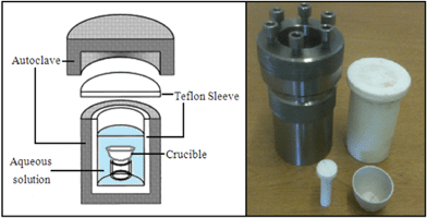 | ||
| Fig. 1 Illustration of the autoclave used in the hydrothermal synthesis with the Teflon holder and crucible. | ||
After each synthesis run, the autoclaves were taken out of the oven and left at room temperature to cool down. The powder samples were washed with deionised water to obtain a pH below 8 and retained for XRD/SEM analysis.
Results
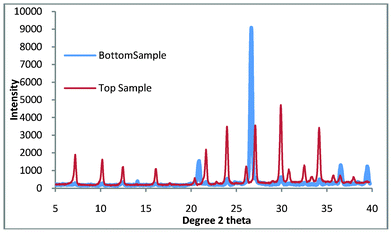
The results which are discussed are referred to as ‘top sample’ and ‘bottom sample.’ These are the final products which are found in the crucible and the bottom of the autoclave. Fig. 2 shows the top and bottom product for zeolite A synthesis at 100 °C for 3 h.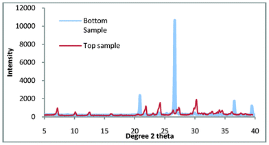 | ||
| Fig. 2 The top and bottom samples for zeolite A synthesis. | ||
When shown with a standard zeolite Fig. 3 it is apparent that there is a very small amount of impurity in the top sample. Given the percentage of quartz in the untreated kaolin (77.3 wt.%) this is not surprising but disappointing as quartz is a very abrasive material and as such severely limits the applications for which this zeolite could be used.
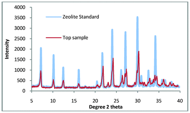 | ||
| Fig. 3 Top sample compared with a commercial standard of zeolite A. | ||
In our previous study we demonstrated the growth of pure zeolite from ‘impure’ natural kaolin. This material had been processed using extensive settling and flocculation to give a quartz content of 2.5 wt.%. This compares favourably with a standard sample (supplied by WBB) which has been calculated to contain 4.6 wt.% quartz. The purpose of this work was to use untreated kaolin to manufacture pure zeolite, as a consequence of the impurities in Fig. 3, the synthesis gel was refined slightly. The synthesis solution was found to be ‘cloudy’ when produced, the implication being that colloidal impurities are in suspension and these are slightly contaminating the top product. The work was repeated but in this experiment, the raw kaolin (50 g) was briefly stirred with distilled water (300 ml), this was then allowed to stand for 10 min and then the liquid was decanted. This was repeated twice and then the sample was dried overnight at 60 °C, it was hoped that this would remove any colloidal impurities. The suspended solids were collected and the XRD pattern is shown in Fig. 4. The pattern shows that the composition is very similar to the starting material and would explain the presence of a small amount of impurity in the non-washed process. Using this method, a 5% loss of mass of kaolin product was measured but this loss is compensated by the energy and time benefits of the reduced settling time over the flocculation/settling pre-treatment previously used.
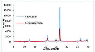 | ||
| Fig. 4 The suspended solids and bulk kaolin from the ‘cursory’ washing of the virgin kaolin. | ||
The synthesis method was repeated and it was found that the synthesis gel produced a clear aqueous phase. After thermal treatment at 100 °C for 3 h, the product that was produced is shown in Fig. 5.
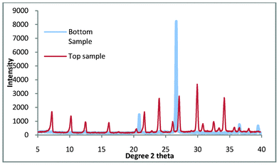 | ||
| Fig. 5 Top and bottom products for zeolite A synthesis where the colloidal impurities have been decanted. | ||
It is clearly shown in Fig. 5 that the bottom product consists entirely of quartz while the top product appears to be pure zeolite A. Fig. 6. shows the comparison of the top product with a zeolite A standard and it is apparent that the product is pure zeolite A.
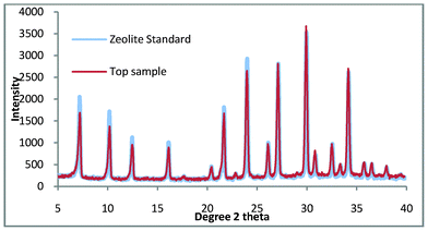 | ||
| Fig. 6 Top product for zeolite A synthesis where the colloidal impurities have been decanted compared with a commercial standard. | ||
The SEM image of the zeolite A (top product) is shown in Fig. 7 with the distinctive cubic structure of zeolite A being apparent. The SEM shows the crystal size to be approximately 2 μm demonstrating that significant growth has occurred on the colloidal seeds which have been shown by Dynamic Light Scattering studies to have an average size of 42 nm.
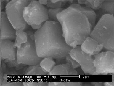 | ||
| Fig. 7 Top product for zeolite A synthesis where the colloidal impurities have been decanted. | ||
The SEM of the bottom product is shown in Fig. 8, and it is apparent that there is no zeolite growth and the material has the appearance of the plate-like structure you would expect from quartz.
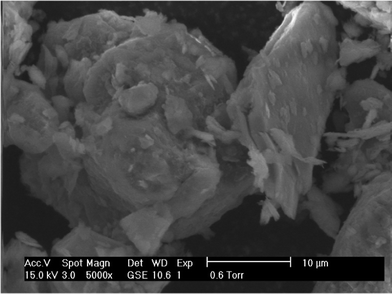 | ||
| Fig. 8 Bottom product for zeolite A synthesis where the colloidal impurities have been decanted. | ||
This work is aimed at reducing both the time and cost of zeolite A production, one final refinement is the removal of the need for the sonication of the colloidal seeds to the crucible prior to growth. This is carried out to ensure that the seeds do not become suspended in the aqueous phase and then mix with the bottom product. The sonication step is both lengthy and energy intensive. By using the ball mill slurry as seeds rather than the suspended solids we can overcome the need for the sonication step, the slurry was found by DLS to have an average particle size of 744 nm. This was carried out and the products were the same as those for the colloidal seeds as shown in Fig. 9.
 | ||
| Fig. 9 Top and bottom products for zeolite A synthesis where the seeds have been replaced by the slurry from the ball mill. | ||
Conclusions
We have successfully synthesised zeolite A from a kaolin which has been extracted directly from source. Unfortunately, the nature of some of the impurities are such that due to their small size they can form a suspension and as such are able to overcome the physical/gravity barrier which has been put in place to stop contamination of the product by quartz. We have overcome this problem by using a cursory washing technique to remove the colloidal contaminants. It is shown that the short settling time used will remove 5% of the total mass of kaolin as well as quartz however, the aim of this study is to produce an economical method of zeolite production and as such it was felt that the short settling time was more important than losing a small amount of kaolin.The ion-exchange capabilities of zeolite A are well known, and as Nigeria has a significant problem with water quality11 the production of economic ion-exchange media may be significant. Clearly, sanitation issues are very significant, but metal ion contamination has been shown to be a hazard in the Niger Delta. Iron, manganese, copper, cadmium, chromium, lead, nickel and zinc have all been shown11 to be above EPA maximum contaminant levels and zeolite A has been shown to be effective in ion-exchange of all of these ions with the exception of Fe.12–16
References
- B. Prasad, S. Maity, K. Sangita, A. K. Mahato and R. J. G. Mortimer, Environ. Technol., 2012, 33, 37–50 CrossRef CAS.
- D. Chen, X. Hu, L. Shi, Q. Cui, H. Wang and H. Yao, Appl. Clay Sci., 2012, 59-#x2013;60, 148–151 Search PubMed.
- A. Y. Atta, B. Y. Jibril, B. O. Aderemi and S. S. Adefila, Appl. Clay Sci., 2012, 61, 8–13 CrossRef CAS.
- Y. Du, S. Shi and H. Dai, Particuology, 2011, 9, 174–178 CrossRef CAS.
- M. Mezni, A. Hamzaoui, N. Hamdi and E. Srasra, Appl. Clay Sci., 2011, 52, 209–218 CrossRef CAS.
- X. Wang, Y. Yuan, X. Chu and G. Tang, Mater. Lett., 2012, 67, 355–357 CrossRef CAS.
- H. Yin, T. Zhou, Y. Liu, Y. Chai and C. Liu, J. Porous Mater., 2012, 19, 277–281 CrossRef CAS.
- S. M. Holmes, S. H. Khoo and A. S. Kovo, Green Chem., 2011, 13, 1152–1154 RSC.
- A. S. Kovo and S. M. Holmes, J. Dispersion Sci. Technol., 2010, 31, 442–448 CrossRef CAS.
- A. S. Kovo, O. Hernandez and S. M. Holmes, J. Mater. Chem., 2009, 19, 6207–6212 RSC.
- J. K. Nduka and O. E. Orisakwe, Environ. Sci. Pollut. Res., 2011, 18, 237–246 CrossRef CAS.
- B. Biskup and B. Subotic, Sep. Sci. Technol., 2000, 35, 2311–2326 CrossRef CAS.
- A. M. El-Kamash, J. Hazard. Mater., 2008, 151, 432–445 CrossRef CAS.
- A. M. El-Kamash, A. A. Zaki and M. A. El Geleel, J. Hazard. Mater., 2005, 127, 211–220 CrossRef CAS.
- A. A. Ismail, R. M. Mohamed, I. A. Ibrahim, G. Kini and B. Koopman, Colloids Surf., A, 2010, 366, 80–87 CrossRef CAS.
- M. Majdan, S. Pikus, M. Kowalska-Ternes, A. Gladysz-Plaska, P. Staszczuk, L. Fuks and H. Skrzypek, J. Colloid Interface Sci., 2003, 262, 321–330 CrossRef CAS.
| This journal is © The Royal Society of Chemistry 2012 |
