Photophysical, electrochemical and photovoltaic properties of dye sensitized solar cells using a series of pyridyl functionalized porphyrin dyes
Dimitra
Daphnomili
b,
Giorgos
Landrou
b,
Surya
Prakash Singh
c,
Anup
Thomas
c,
Kada
Yesudas
c,
Bhanuprakash
K.
c,
G. D.
Sharma
*a and
A. G.
Coutsolelos
*b
aR & D Centre for Engineering and Science, Jaipur Engineering College, Kukas, Jaipur (Raj.) 303101, India. E-mail: sharmagd_in@yahoo.com; gdsharma273@gmail.com
bDepartment of Chemistry, University of Crete, Laboratory of Bioinorganic Chemistry, Voutes Campus, P.O. Box 2208, 71003 Heraklion, Crete, Greece. E-mail: coutsole@chemistry.uoc.gr
cInorganic & Physical Chemistry Division, Indian Institute of Chemical Technology, Uppal Road, Tarnaka, Hyderabad 500607, India
First published on 11th October 2012
Abstract
Three porphyrin dyes, P1, P2 and P3, bearing one, two and four pyridyl groups, respectively, in the meso positions, acting as electron acceptor anchoring groups, were synthesized, characterized and investigated as sensitizers for the fabrication of dye sensitized solar cells (DSSCs). The overall power conversion efficiencies (PCEs) of DSSCs based on these dyes lay in the range 2.46–3.9% using a 12 μm thick TiO2 photoanode. Porphyrin P2 achieved the maximum performance, which can be rationalized by the high dye loading, efficient electron injection, dye regeneration process and longer electron lifetime, as demonstrated by the electrochemical impedance spectroscopy (EIS) measurements. The PCE of the DSSC based on the P2 sensitizer when the photoanode was treated with formic acid, showed an enhanced efficiency of 5.23%. This improvement, attributed to multifunctional properties such as higher dye uptake, reduced recombination process and enhanced charge collection efficiency. Deoxycholic acid (DCA) was also used as a coadsorbent in order to prevent dye aggregation and it was found that the PCE improved up to 6.12% for sensitizer P2 and the modified TiO2 photoanode, which can be attributed to further improvement in the electron injection efficiency and charge collection efficiency.
Introduction
Dye sensitized solar cells (DSSCs) are considered to be promising candidates for the next generation of solar cells because they provide an economic alternative over silicon based solar cells, due to their low cost and facile manufacturing processes.1–3 DSSCs based on ruthenium Ru(II) complexes have broad absorption spectra extending into the near infrared (NIR) region and produce power conversion efficiencies (PCEs) up to 11.7% under AM1.5 irradiation.4–8 However, Ru(II) based dyes are expensive due to the high cost of ruthenium and the typically lengthy purification steps involved in their preparation. Also, environmental concerns associated with the use of these dyes inspired strenuous efforts in order to find novel dyes that do not rely on Ru or other expensive materials. Therefore, much effort has been devoted to the development of new efficient metal-free organic sensitizers9–14 exhibiting high molar absorption coefficients and facile modification of the molecular structures. Highly efficient organic dyes are typically composed of a donor–π–acceptor framework with a well defined architecture.Among all these dyes, porphyrins have attracted considerable attention as light harvesting antennae for DSSCs because of their photochemical and electrochemical stabilities, easy synthesis, and efficiency in capturing solar energy in the visible region with distinct high molar extinction coefficients. Porphyrins' redox potential and therefore their orbital levels can be altered by modification of the periphery substituents, the substitution position, and the central metal.15–19 Although the absorption of Ru complexes is limited beyond the NIR region,6,7 porphyrins show intense absorption in the region 400–500 nm (Soret band) and 500–700 nm (Q-bands), due to their aromatic and macrocyclic structures along with good stability.16,17 Thus, porphyrins and their derivatives can be used as panchromatic photosensitizers. The electron transfer kinetics are indistinguishable from those of the Ru(II) polypyridyl complexes. More importantly, because of their multiple reaction sites, including four meso positions and eight β-positions, their optical, electronic and photophysical properties can be easily modulated by the peripheral substitutions and inner metal complexation.20,21 In principle, the molecular design of porphyrin sensitizers is based on a P–B–A structure, in which B represents a π-conjugation bridge serving as a spacer between the porphyrin light harvesting center P and the anchoring group A. Therefore, numerous porphyrins have been synthesized and used as sensitizers for DSSCs, with a highest PCE of 12.3%, which is even higher than that of the Ru(II)-based sensitizers.22–24
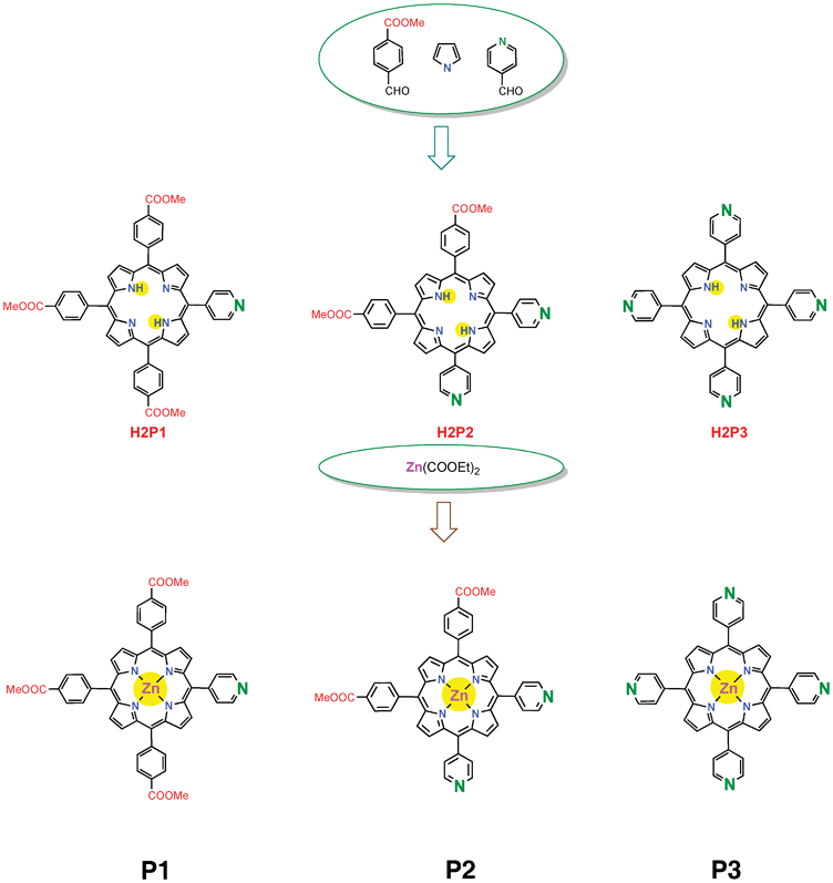
Most of the D–π–A dyes for DSSCs developed so far have a carboxylic acid, cyanoacrylic acid or rhodanine-3-acetic moiety that acts as an electron acceptor and anchoring group for attachment on a TiO2 surface. The carboxyl group enables good electron communication between the dye and TiO2, forming a strong ester linkage between Brønsted acid sites (surface bound hydroxyl groups) of the TiO2 surface. On the other hand, very recently, a new type of D–π–A dye sensitizer with a pyridine ring as an electron withdrawing anchoring group has been developed.25,26 These dyes exhibit a higher short circuit photocurrent (Jsc) and PCE compared to their counterpart dyes having carboxyl groups. It was reported that the formation of coordinate bonds between the pyridine ring of the dye and the Lewis acid sites of the TiO2 surface leads to efficient electron injection owing to good electron communication between them rather than the formation of an ester linkage between the dyes having a carboxyl anchoring group. In this work, to ensure the usefulness of the pyridine ring as an effective electron injecting group, a series of a new type of D–π–A porphyrin dyes, P1, P2 and P3, comprising of one, two and four pyridine rings, respectively, at different meso positions were synthesized. The relationship between the number of pyridine rings (anchoring groups) and the photophysical, electrochemical, and photovoltaic properties of porphyrin dyes is investigated. These porphyrin dyes were employed as photosensitizers for the fabrication of DSSCs. Among these porphyrin sensitizers P2 showed higher PCE than the others.
Experimental details
Experimental
1H spectra were recorded on a Bruker AMXDPX-500 or on a 300 MHz spectrometer and referenced to the residual protonated solvent. High-resolution mass spectra were obtained on a Bruker ultrafleXtreme MALDI-TOF/TOF spectrometer. Solvents (ACS for analysis) and chemicals were purchased from Aldrich. All measurements were performed at room temperature.UV-visible absorption spectra of the porphyrins in CHCl3/MeOH/Et3N (8![[thin space (1/6-em)]](https://www.rsc.org/images/entities/char_2009.gif) :
:![[thin space (1/6-em)]](https://www.rsc.org/images/entities/char_2009.gif) 2
2![[thin space (1/6-em)]](https://www.rsc.org/images/entities/char_2009.gif) :
:![[thin space (1/6-em)]](https://www.rsc.org/images/entities/char_2009.gif) 0.5) solution porphyrin monolayers on TiO2 electrodes were recorded on the Perkin Elmer Lambda spectrophotometer. Electrochemical measurements were made using an electrochemical analyzer. Redox potentials of the porphyrins were determined by cyclic voltammetry in DMF containing 0.1 M tetrabutylammonium hexafluorophosphate (Bu4NPF6) as a supporting electrolyte. A glassy carbon working electrode (3 mm diameter), Ag/AgCl (0.01 M in acetonitrile) reference electrode, and Pt wire counter electrode were employed. Ferrocene/ferrocenium (+0.642 V vs. NHE) was used as an internal standard for all measurements. All of the measured potentials were converted to the NHE scale.
0.5) solution porphyrin monolayers on TiO2 electrodes were recorded on the Perkin Elmer Lambda spectrophotometer. Electrochemical measurements were made using an electrochemical analyzer. Redox potentials of the porphyrins were determined by cyclic voltammetry in DMF containing 0.1 M tetrabutylammonium hexafluorophosphate (Bu4NPF6) as a supporting electrolyte. A glassy carbon working electrode (3 mm diameter), Ag/AgCl (0.01 M in acetonitrile) reference electrode, and Pt wire counter electrode were employed. Ferrocene/ferrocenium (+0.642 V vs. NHE) was used as an internal standard for all measurements. All of the measured potentials were converted to the NHE scale.
The TiO2 paste prepared by mixing 1 g TiO2 powder (P25 Degussa), 0.2 mL acetic acid and 1 mL water, as reported in our earlier communication.27 The cleaned fluorine doped tin oxide (FTO) coated glass substrate was immersed into 40 mM TiCl4 (aq) at 60 °C to form a compact blocking layer and then washed with water and ethanol. After drying, the substrate was coated with a layer of prepared TiO2 paste by the doctor blade technique and kept in a clean box for 10 min and finally dried for another 10 min at 100 °C. This doctor blade technique was repeated a few times until we achieved the desired film thickness. The electrodes coated with the TiO2 pastes were gradually heated to 450 °C and sintered for 30 min. For post treatment of the TiO2 surface, the sintered electrodes were subjected to TiCl4 treatment as described previously and then washed with distilled water and ethanol and sintered again at 450 °C for 30 min, followed by cooling to 60 °C. The TiO2 coated FTO electrode was soaked in CHCl3/MeOH (2![[thin space (1/6-em)]](https://www.rsc.org/images/entities/char_2009.gif) :
:![[thin space (1/6-em)]](https://www.rsc.org/images/entities/char_2009.gif) 5) solution of 0.5 mM porphyrin P1 or P2 or P3 for 12 h at room temperature. The dye coated TiO2 films were washed with ethanol and dried.
5) solution of 0.5 mM porphyrin P1 or P2 or P3 for 12 h at room temperature. The dye coated TiO2 films were washed with ethanol and dried.
For the modified photoelectrode, prior to sensitization, the TiO2 electrode was treated with formic acid (0.05 M in ethanol solution) for 2 h, which resulted in an increase in the number of hydroxyl groups and adsorbed formate acid (HCOO−) on the surface.28 The dye coated TiO2 films were assembled with a Pt coated counter electrode prepared by spin casting of drops of 10 mM H2PtCl6 solution in ethanol and then heating at 400 °C for 20 min. Two active electrodes i.e. TiO2 coated FTO photoelectrode and Pt coated FTO counter electrode were separated with a 30 μm spacer. This space was filled with a liquid electrolyte. The electrolyte used for the fabrication of DSSCs consists of LiI, (0.05 M), I2 (0.5 M), dimethyl-propyl-benzimidazole iodide (DPMII), (0.6 M) and 4-tert-butylpyridine (TBP) (0.5 M) in acetonitrile solution.
The current–voltage characteristics of the DSSCs were measured using a digital source meter (Keithley model) under the standard air mass (AM1.5) with a xenon lamp coupled with optical filter, at an illumination intensity of 100 mW cm−2. The incident photon to current efficiency of the DSSCs was measured using a system consisting of a monochromator and xenon lamp and the short circuit photocurrent was measured a with Keithley electrometer.
The electrochemical impedance spectra (EIS) measurements of DSSCs were carried out by applying a bias equivalent to the Voc of the device and recording over a frequency of 1 mHz to 105 Hz with an ac amplitude of 10 mV, under illumination and in the dark. The above measurements were carried out using a potentiostat (PGSTAT 30 Autolab, Eco-Chemie) in both the dark as well as under illumination, equipped with FRA.
Computational method
All computational methods in this study were carried out with the Gaussian 09 suite of programs.29 The molecular structures of the porphyrin dyes P1, P2 and P3 that were studied are shown in Fig. 1. The geometry optimizations were carried out without symmetry constraints at the DFT-B3LYP and were followed by frequency calculations in order to ensure that real minima were obtained. The optimized geometries were then subjected to the time dependent-density functional theory (TDDFT) calculations at the M06 level in order to obtain the S0→S1 higher excited state transition energies of up to 12 excited states and their corresponding transition dipole moments. In order to take into account the effect of the medium, the implicit solvation model was used, by employing the self-consistent reaction field (SCRF) method in conjunction with the polarizable continuum model (PCM)30 and dichloromethane (ε = 8.93) as a dielectric medium. In all our calculations, we used 6-31G** for the lighter atoms and the LANL2DZ basis set for the Zn metal atom.Results and discussion
Synthesis of porphyrin dyes
![[thin space (1/6-em)]](https://www.rsc.org/images/entities/char_2009.gif) :
:![[thin space (1/6-em)]](https://www.rsc.org/images/entities/char_2009.gif) 0.5 v/v, yield 36%). HRMS (MALDI-TOF): m/z calcd for C49H35N5O6 + H+: 790.2666 [M + H]+. Found: 790.2672. 1H NMR (500 MHz, CDCl3): δ 9.05 (d, J = 5.7 Hz, 2H), 8.84 (m, 8H), 8.46 (m, 6H), 8.3 (m, 6H), 8.17 (d, J = 5.7, 2H), 4.14 (s, 12H), −2.83 (s, 2H).
0.5 v/v, yield 36%). HRMS (MALDI-TOF): m/z calcd for C49H35N5O6 + H+: 790.2666 [M + H]+. Found: 790.2672. 1H NMR (500 MHz, CDCl3): δ 9.05 (d, J = 5.7 Hz, 2H), 8.84 (m, 8H), 8.46 (m, 6H), 8.3 (m, 6H), 8.17 (d, J = 5.7, 2H), 4.14 (s, 12H), −2.83 (s, 2H).
Chromatography on SiO2 afforded the desired product with CH2Cl2/EtOAc (100![[thin space (1/6-em)]](https://www.rsc.org/images/entities/char_2009.gif) :
:![[thin space (1/6-em)]](https://www.rsc.org/images/entities/char_2009.gif) 30 v/v, yield 16%) HRMS (MALDI-TOF): m/z calcd for C46H32N6O4 + H+: 733.2563 [M + H]+. Found: 733.2558. 1H NMR (500 MHz, CDCl3): δ 9.08 (m, 4H), 8.87 (m, 8H), 8.49 (m, 4H), 8.32 (m, 4H), 8.2 (m, 4H), 4.22 (s, 6H), −2.93(s, 2H).
30 v/v, yield 16%) HRMS (MALDI-TOF): m/z calcd for C46H32N6O4 + H+: 733.2563 [M + H]+. Found: 733.2558. 1H NMR (500 MHz, CDCl3): δ 9.08 (m, 4H), 8.87 (m, 8H), 8.49 (m, 4H), 8.32 (m, 4H), 8.2 (m, 4H), 4.22 (s, 6H), −2.93(s, 2H).
Metallation
Metallation of all free bases with Zn was performed in a mixture of CH2Cl2/MeOH (4![[thin space (1/6-em)]](https://www.rsc.org/images/entities/char_2009.gif) :
:![[thin space (1/6-em)]](https://www.rsc.org/images/entities/char_2009.gif) 2 v/v) with 5 equiv excess of Zn(CH3COO)2 at room temperature. The yield in each case was quantitative.
2 v/v) with 5 equiv excess of Zn(CH3COO)2 at room temperature. The yield in each case was quantitative.
DFT Calculations
The electronic absorption spectrum of a typical porphyrin consists of a strong transition to the second excited state (S0→S2) at about 400 nm (the Soret or B band) and a weak transition to the first excited state (S0→S1) at about 550 nm (the Q band). The B and Q bands both arise from π–π* transitions and can be explained by considering the four orbitals (HOMO − 1, HOMO, LUMO and LUMO + 1 orbitals) (the Gouterman four orbital model). According to this theory, the absorption bands in porphyrin systems arise from transitions between two HOMOs and two LUMOs, and it is the identities of the metal center and the substituents on the ring that affect the relative energies of these transitions. But, since the ZnII metal incorporated into the core of the porphyrin has a d10 electronic configuration, the dπ (dxz, dyz) metal-based orbitals are relatively low in energy. These have very little effect on the porphyrin π→π energy gap in porphyrin electronic spectra, which is in contrast to metalloporphyrins having unpaired electrons and involves charge transfer transitions from the metal to the ligand. The highest two occupied MOs are nearly degenerate and strongly coupled to each other. This coupling splits these two states in energy, creating a higher energy state with a greater oscillator strength, giving rise to the Soret or B-band, and a lower energy state with less oscillator strength, giving rise to the Q-bands. The results of our calculations are presented in Table 1 for the last three bands. The Q-bands in all the molecules appeared at 2.21, 2.21 and 2.22 eV with oscillator strengths of 0.020, 0.024, and 0.012, respectively. This involves the major transitions from HOMO→LUMO + 1, HOMO − 1→LUMO and is in good agreement with the experimental value of 2.22 eV. This corresponds to the π→π transition occurring in the core porphyrin. The additional peak was observed for all the porphyrin dyes in the red region with relatively low intensity. The B-band appeared at wavelengths corresponding to 3.06, 3.04 and 3.09 eV with a large oscillator strength of 1.774, 1.898 and 1.678, respectively, for P1, P2 and P3. These values are deviated by 0.15 eV from the experimentally observed values. The shoulder peak with a much lower oscillator strength has a major contribution from the HOMO − 1→LUMO and HOMO − 1→LUMO + 1 transitions and showed a large deviation from the experimental value. The schematic representation of the electronic transitions is shown in Fig. 2 for the P2 molecule. Similar transitions are observed for P1 and P3. Also, the presence of the electron withdrawing groups does not change the nature of these transitions and is similar to the free base porphyrin.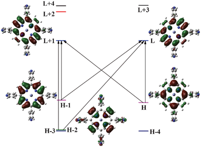 | ||
| Fig. 2 Molecular orbitals and transitions for P2; similar orbitals and transitions have been obtained for other dyes. | ||
| Molecule | E ge | λ | f | E ge Expt. |
|---|---|---|---|---|
| P2 | 2.21 | 561 | 0.020 | 558 (2.22) |
| 3.06 | 405 | 1.774 | 426 (2.91) | |
| 3.68 | 339 | 0.001 | 405 (3.06) | |
| P1 | 2.21 | 562 | 0.024 | 558 (2.22) |
| 3.04 | 408 | 1.898 | 427 (2.90) | |
| 3.53 | 351 | 0.002 | 407 (3.05) | |
| P3 | 2.22 | 558 | 0.012 | 558 (2.22) |
| 3.09 | 401 | 1.678 | 427 (2.90) | |
| 3.74 | 331 | 0.051 | 408 (3.04) |
Optical and electrochemical properties
The UV-visible absorption spectra of porphyrin dyes in CHCl3/MeOH/EtN3 (8![[thin space (1/6-em)]](https://www.rsc.org/images/entities/char_2009.gif) :
:![[thin space (1/6-em)]](https://www.rsc.org/images/entities/char_2009.gif) 2
2![[thin space (1/6-em)]](https://www.rsc.org/images/entities/char_2009.gif) :
:![[thin space (1/6-em)]](https://www.rsc.org/images/entities/char_2009.gif) 0.5 v/v) and emission spectra in EtOH/MeOH (4
0.5 v/v) and emission spectra in EtOH/MeOH (4![[thin space (1/6-em)]](https://www.rsc.org/images/entities/char_2009.gif) :
:![[thin space (1/6-em)]](https://www.rsc.org/images/entities/char_2009.gif) 1) glass at 77 K are shown in Fig. 3 and 4, respectively. The emission spectra of the porphyrin dyes were measured in EtOH/MeOH 4
1) glass at 77 K are shown in Fig. 3 and 4, respectively. The emission spectra of the porphyrin dyes were measured in EtOH/MeOH 4![[thin space (1/6-em)]](https://www.rsc.org/images/entities/char_2009.gif) :
:![[thin space (1/6-em)]](https://www.rsc.org/images/entities/char_2009.gif) 1 in a glass cuvette with excitation at 550 nm. Owing to their similar structures, all the porphyrin dyes exhibit strong absorption peaks located in the range 400–440 nm (Soret band) and weak Q bands around 550–620 nm, which are attributed to π–π* electronic transitions. In addition, it was found that the electronic interaction between the porphyrin core and the bridging group also affects the electronic structure, presumably as a result of increasing the extent of π-conjugation. Eoo is determined from the position of the highest energy vibronic feature in the fluorescence spectra of the compounds measured at 77 K and these values are compiled in Table 2.
1 in a glass cuvette with excitation at 550 nm. Owing to their similar structures, all the porphyrin dyes exhibit strong absorption peaks located in the range 400–440 nm (Soret band) and weak Q bands around 550–620 nm, which are attributed to π–π* electronic transitions. In addition, it was found that the electronic interaction between the porphyrin core and the bridging group also affects the electronic structure, presumably as a result of increasing the extent of π-conjugation. Eoo is determined from the position of the highest energy vibronic feature in the fluorescence spectra of the compounds measured at 77 K and these values are compiled in Table 2.
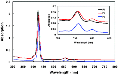 | ||
| Fig. 3 Optical absorption spectra of P1, P2, and P3 porphyrin dyes in solution. | ||
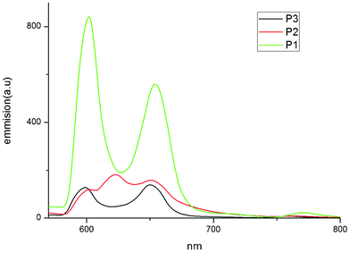 | ||
| Fig. 4 Emission spectra of P1, P2 and P3 porphyrin dyes. | ||
| Dye | E ox (V vs. NHE)a | E oo (eV)b | E*ox (V vs. NHE)c | ΔGinj (eV)d | ΔGreg (eV)e |
|---|---|---|---|---|---|
a First oxidation potential (vs. NHE) (corresponds to HOMO energy level) observed in cyclic voltammogram.
b Taken from the position of the highest energy vibronic feature in the fluorescence spectra of the compounds measured at 77 K in a EtOH/MeOH 4![[thin space (1/6-em)]](https://www.rsc.org/images/entities/char_2009.gif) : :![[thin space (1/6-em)]](https://www.rsc.org/images/entities/char_2009.gif) 1 glass.
c Excited state (corresponds to the LUMO energy level) approximated from Eox − Eoo (vs. NHE).
d Driving force for electron injection from the porphyrin LUMO energy level to the conduction band of TiO2 (−0.5 V vs. NHE).
e Driving force for regeneration of porphyrin radical cations by I−/I−3 redox couple (−0.5 V vs. NHE). 1 glass.
c Excited state (corresponds to the LUMO energy level) approximated from Eox − Eoo (vs. NHE).
d Driving force for electron injection from the porphyrin LUMO energy level to the conduction band of TiO2 (−0.5 V vs. NHE).
e Driving force for regeneration of porphyrin radical cations by I−/I−3 redox couple (−0.5 V vs. NHE).
|
|||||
| P1 | 0.91 | 2.060 | −1.15 | 0.83 | 0.41 |
| P2 | 0.83 | 2.062 | −1.23 | 0.99 | 0.33 |
| P3 | 0.94 | 2.072 | −1.13 | 0.74 | 0.44 |
Fig. 5 shows the absorption spectra of porphyrins adsorbed on a TiO2 film. These figures show that both the Soret and Q bands of porphyrin/TiO2 films are slightly red shifted and become broader compared to the solution spectra. Generally, when sensitizers are anchored onto a nanocrystalline TiO2 surface, deprotonation and H-aggregates result in a blue shift, while J-aggregates usually lead to a red shift. These observations can be related to J-type aggregation of the porphyrins on the TiO2 surfaces.33–36 The broadened absorption bands and the red shifted absorption onset on the thin film afforded increased light harvesting and better utilization of long wavelength light. The absorption spectra of porphyrins/TiO2 demonstrate that the binding behavior of the zinc porphyrin depends on the number and position of the anchoring groups. The absorbance and molecular loading on TiO2 for P2 (possessing two cis-pyridyl anchoring groups) is higher than that for the other porphyrin dyes. The possible mode of the attachment of P1, P2 and P3 on the TiO2 surface is shown in Fig. 6.
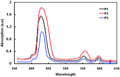 | ||
| Fig. 5 Optical absorption spectra of porphyrin dyes adsorbed onto 4 μm thick TiO2 film. | ||
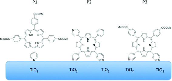 | ||
| Fig. 6 The three pyridyl derivatives and their possible positions on the TiO2 surface. | ||
For a typical sensitizer, suitable highest occupied molecular orbital (HOMO) and lowest unoccupied molecular orbital (LUMO) energy levels are required to enable efficient dye regeneration and electron injection processes. The oxidation potential (Eox) corresponding to the HOMO energy levels of the porphyrin dyes were determined via cyclic voltammetry and summarized in Table 2, which are consistent with the values reported for other porphyrin dyes.37 The reduction potential corresponding to the LUMO energy level was estimated from the difference in Eox and Eoo and is compiled in Table 2. As shown in Table 2, the sufficiently low HOMO energy level of the dye will ensure that there is a large enough driving force for the dye regeneration reaction to compete efficiently with the recapture of the injected electrons by the dye cation radicals. The LUMO energy level is more negative than the conduction band edge of TiO2 (−0.5 V vs. NHE), indicating sufficient driving force for electron injection from the excited dye molecules to the conduction band of the TiO2 photoanode.38
To get information about the interfacial binding between the porphyrin dyes with the pyridine anchoring group and the TiO2 surface, we have recorded the FTIR spectra of all porphyrin dyes in power form and adsorbed onto the TiO2 surface. All the porphyrin dyes showed characteristic stretching bands of C–C or C![[double bond, length as m-dash]](https://www.rsc.org/images/entities/char_e001.gif) N bands at around 1600, 1492 and 1452 cm−1 and also a band around 1720 cm−1, assigned to the methyl ester group in powder form. When the porphyrin dye is adsorbed onto the TiO2 surface, a new band appears around 1456 cm−1, which is assigned to the pyridine ring coordinated to the Lewis acid sites of the TiO2 surface. This indicates that porphyrin dye with a pyridyl anchoring group is predominantly adsorbed on the TiO2 surface by coordinate bonding at the Lewis acid sites (exposed Tin+ cations). This coordinate bonding is also responsible for the red shift of absorption peaks for a porphyrin adsorbed on the TiO2 surface.39
N bands at around 1600, 1492 and 1452 cm−1 and also a band around 1720 cm−1, assigned to the methyl ester group in powder form. When the porphyrin dye is adsorbed onto the TiO2 surface, a new band appears around 1456 cm−1, which is assigned to the pyridine ring coordinated to the Lewis acid sites of the TiO2 surface. This indicates that porphyrin dye with a pyridyl anchoring group is predominantly adsorbed on the TiO2 surface by coordinate bonding at the Lewis acid sites (exposed Tin+ cations). This coordinate bonding is also responsible for the red shift of absorption peaks for a porphyrin adsorbed on the TiO2 surface.39
The preparation of the TiO2 film was optimized in order to get high photovoltaic performance from the DSSC. The thickness of the TiO2 film is one of the important factors, and also affects the PCE of the DSSC. The current–voltage characteristics have been measured under illumination (100 mW cm−2) of DSSCs sensitized with P2 porphyrin dye and with different thicknesses of TiO2 films (6, 10, 12 and 16 μm). All photovoltaic parameters are shown in Table 3. An increase in the PCE of the DSSC from 2.22% to 3.90% was noticed for the DSSC, when the thickness of TiO2 increased from 6 to 12 μm. Further increase in the thickness of TiO2 leads to a decrease in PCE. It has been reported in the literature that the thicker the TiO2 films, the more dye molecules can be adsorbed on the surface.40,41 These results indicate that the diffusion length of photo-excited electrons travelling in the TiO2 particle network is limited to less than around 12 μm. The electron transporting length becomes longer with thicker TiO2 films, which may cause higher probability of recombination; as a result, the Jsc decreases with further increase in the thickness of the TiO2 film. Moreover, the open circuit voltage (Voc) of the DSSC decreases as the thickness of TiO2 film increases, which could be attributed to increased probability of recombination, owing to a longer electron transporting path. The FF also decreases with increasing thickness of the TiO2 film, due to the larger series resistance of the thicker TiO2 film.42
| Thickness (μm) | Short circuit current (Jsc) (mA cm−2) | Open circuit voltage (Voc) (V) | Fill factor (FF) | Power conversion efficiency (PCE) (%) |
|---|---|---|---|---|
| 6 | 6.34 | 0.67 | 0.52 | 2.27 |
| 8 | 7.36 | 0.65 | 0.54 | 2.58 |
| 10 | 8.72 | 0.64 | 0.57 | 3.18 |
| 12 | 10.56 | 0.64 | 0.60 | 3.90 |
| 14 | 9.33 | 0.62 | 0.58 | 3.35 |
The optimized thickness TiO2 film for DSSCs is about 12 μm, therefore the DSSCs sensitized with P1, P2, and P3, were prepared using 12 μm thick TiO2 film as the photoanode. The current–voltage characteristics under illumination (intensity of 100 mW cm−2) of the DSSCs based on these porphyrin dyes are shown in Fig. 7a and the device performance parameters are listed in Table 4. The overall PCE lies in the range 2.46%–3.9%, exhibiting an order of P3 < P1 < P2. Thus, the DSSC based on the sensitization of P2 exhibits the highest PCE, which corresponds to the highest Jsc. The resulting HOMO level of P2 is more positive than those of other porphyrin dyes, therefore the dye regeneration efficiency for DSSCs based on the P2 may be higher. On the other hand, the LUMO level of P2 is more negative than those of the other porphyrin dyes, so that the electron injection efficiency is higher compared to other porphyrin dyes. Hence the DSSC based on P2 exhibited the highest PCE of 3.9%.
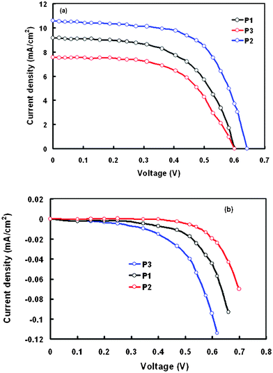 | ||
| Fig. 7 Current–voltage characteristics of the DSSCs sensitized with P1, P2 and P3 under (a) illumination intensity 100 mW cm−2 and (b) in the dark. | ||
| Dye | J sc (mA cm−2) | V oc (V) | FF | PCE (%) | Amount of dye loading (nmol cm−2) |
|---|---|---|---|---|---|
| P1 | 9.2 | 0.60 | 0.56 | 3.10 | 45 |
| P2 | 10.56 | 0.64 | 0.60 | 3.90 | 56 |
| P3 | 7.6 | 0.60 | 0.54 | 2.46 | 35 |
Since the surface coverage i.e. dye loading of the dye sensitized TiO2 film is an important factor in order to determine the photocurrent generation, the amount of dye adsorbed onto the TiO2 surface was measured for these sensitizers. The total amount of porphyrin dye adsorbed onto the TiO2 film was determined by measuring the absorbance of the dye, which was dissolved from the dye coated TiO2 film onto CHCl3 with 0.1 mL NaOH (0.1 M). The adsorbed amounts for these dyes are summarized in Table 4, showing a maximum loading for dye P2 compared to P1 and P3. The high dye loading may be due to the relative positions of the two pyridine and two COOMe groups attached to the meso positions. Therefore, the higher PCE for the DSSC based on the P2 sensitizer may be attributed to its high dye loading and superior light harvesting efficiency to generate more electrons in the excited state of the dye. However, it should be noted that the sole generation of more electrons would not result in higher Jsc, because it also depends on the electron injection efficiency and collection efficiency of electrons. Table 4 also shows that the DSSC based on the P2 sensitizer also exhibits the highest fill factor, indicating reduced recombination. On the basis of J–V curves obtained in the dark (Fig. 7b), the DSSC based on P2 shows a low dark current with respect to other porphyrin dyes (the order of dark current is P3 > P1 > P2). Because the impedance of the electron transfer between TiO2 and the electrolyte governs the dark current, the adsorbed porphyrin dyes on TiO2 might play a role in increasing the interfacial impedance depending on the degree of coverage of sensitizing dyes on the surface of the TiO2. According to the results of dye loading, P2 gives significant high molecular loading on TiO2, behaving like a blocking layer in order to prevent charge recombination between the electrons in TiO2 and tri-iodides in the electrolyte. For the P3 dye, which has the lowest surface coverage on TiO2, the tri-iodide in the electrolyte can penetrate close to the surface of TiO2 in order to decrease the barrier for the electrons to combine with tri-iodides and to result in a high dark current. The lowest PCE of the DSSC based on P3 can be attributed to the small amount of dye loading and the high dark current due to the significant effect of charge recombination.
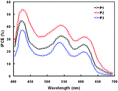
The IPCE spectra of the DSSCs sensitized with P1, P2 and P3 are shown in Fig. 8. The IPCE spectra follow the absorption spectra of the corresponding dyes adsorbed on the TiO2 film. It can be seen from Fig. 8 that the values of IPCE at each wavelength are higher for DSSC sensitized with P2 as compared to P1 and P3, which is good agreement with the Jsc and PCE values observed from the J–V characteristics of the DSSCs. It means the photons correspond to the longer wavelength regions also contribute to the photocurrent.
In order to investigate the interrelation between the number of anchoring units in dyes and the photovoltaic properties of the DSSCs, electrochemical impedance spectral (EIS) analyses were performed in the dark. EIS analysis provides information on the interfacial charge transfer process.43–45Fig. 9a shows the typical Nyquist plots at an applied voltage of −0.6 V. In the Nyquist plots, the high frequency semicircle on the left side corresponds to the charge transfer process at the counter electrode Pt/redox (I−/I−3) interface and the middle frequency semicircle on the right side corresponds to the electron transport process at the TiO2/dye/electrolyte interface. The radii of the semicircles lie in the order P2 > P1 > P3, indicating the sequence of the charge transfer resistance at the interface. In Bode plots (Fig. 9b), the peak at higher frequencies corresponds to the charge transfer at the counter electrode and the peak in the lower frequency region is related to the charge recombination rate and its reciprocal is regarded as the electron lifetime.46–48 The peak maximum is shifted to a lower frequency from P3 to P1 in the same sequence as that observed for the value of PCE. Electron lifetimes for P1, P2 and P3 are 19 ms, 28 ms and 14 ms, respectively. Therefore, the DSSC based on P2 has the longest electron lifetime, indicative of a more effective suppression of the back reaction between the injected electrons and the electrolyte, resulting in the improvement of the Voc due to the reduced charge recombination rate. The reduction in the recombination rate also leads to higher value of Voc. The combination of the higher Voc and Jsc values leads to the higher value of PCE for the DSSC based on porphyrin dye P2. The electron lifetimes for the DSSCs based on these porphyrin dyes are lower compared to Ru based DSSC, which may be responsible for the lower values of the FF observed in these devices, which may also be attributed to the larger value of series resistance. Moreover, the FF depends upon the charge collection efficiency, which is also lower than that of the DSSCs of the Ru based dyes.
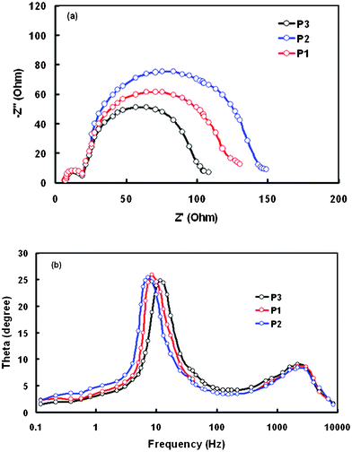 | ||
| Fig. 9 (a) Nyquist plots (b) Bode phase plots of EIS obtained for the DSSCs based on P1, P2 and P3 in the dark. | ||
In general, Zn-pyridyl porphyrins usually form aggregates through the coordination of Zn of one porphyrin ring to the pyridyl group of another porphyrin ring. Aggregate formation may be more pronounced for the tetrapyridyl than the monopyridyl complex. The formation of the aggregates leads to a lower PCE, as observed in P3. The formation of aggregates may be less for the porphyrin P2 with two pyridyl rings.
The PCE of the DSSC based on P2 is maximum among the three porphyrin dyes used for sensitization, but is still low compared to other porphyrin dyes reported in the literature.22,23,38 This may be due to the poor dye loading, which arises because of improper sensitization. We have modified the TiO2 photoanode as described in the experimental section and used P2 with and without coadsorbent deoxycholic acid (DCA). The current–voltage (J–V) characteristics of the DSSC based on a modified TiO2 anode and P2 as a sensitizer with and without DCA (Fig. 10) and the photovoltaic parameters are compiled in Table 5. Higher performance was achieved for the DSSC using a modified photoanode. The DSSC based on a modified TiO2 photoanode exhibits a Jsc of 12.04 mA cm−2, Voc of 0.68 V and FF of 0.64, and thus higher PCE up to 5.23%. The DSSC fabricated with DCA coadsorbent in the P2 dye showed a PCE of 6.12% with Jsc = 12.86 mA cm−2, Voc = 0.70 V and FF = 0.68. The amount of dye loading for the modified photoanode was measured and found to have increased. In a modified photoanode, the adsorbed formate ions on the TiO2 surface provide anchoring sites for porphyrin dye absorption. The Jsc for the DSSC based on the modified photoanode may be attributed to its high dye loading and superior light harvesting properties, which generate more electrons. The PCE of the DSSC depends on the light harvesting properties, electron injection efficiency and charge collection efficiency. Therefore, the generation of more electrons solely will not result in higher Jsc, because it also depends on the injection and collection efficiency of the electrons. Hence the DSSC based on the modified TiO2 photoanode is likely to have a higher electron injection efficiency and collection efficiency, as evidenced from EIS studies.
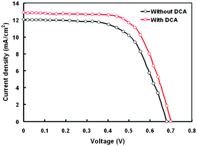 | ||
| Fig. 10 Current–voltage characteristics of DSSCs based on the modified TiO2 photoanode and P2 sensitizer with and without a DCA coadsorbent. | ||
| Dye | J sc (mA cm−2) | V oc (V) | FF | PCE (%) | Amount of dye loading (nmol cm−2) |
|---|---|---|---|---|---|
| P2 | 12.04 | 0.68 | 0.64 | 5.24 | 64 |
| DCA-P2 | 12.86 | 0.70 | 0.68 | 6.12 | 52 |
The modified photoanode also exhibits higher FF, indicating reduced recombination. The charge recombination can be estimated by the magnitude and onset of dark current, which arises from the reduction of I−3 ions by the electrons. The dark current onset occurs at a higher potential for the modified photoanode than the un-modified DSSC. The modified DSSC produced less dark current than the unmodified photoanode DSSC at a given potential above 560 V, indicating low recombination of the transported electrons and I−3 ions in the electrolyte resulting in high Voc and FF.
EIS data have been used to obtain information about the charge collection efficiency and recombination kinetics in the DSSC based on modified and unmodified photoanodes. Information about the electron lifetime, effective diffusion length, transport resistance etc., could be estimated from the impedance spectra of DSSCs. The Nyquist plot of the DSSC in the dark based on the modified photoanode (Fig. 11a) seems to be similar to that for the unmodified one (Fig. 9a). However, the radius in the middle frequency region corresponding to the charge transfer at TiO2/dye/electrolyte, for the modified photoanode is larger than that for the unmodified, indicating higher charge transfer resistance of the recombination process at the TiO2/dye/electrolyte interface (Rct). The higher value of Rct for the modified anode accounts for the longer electron lifetime. Therefore, we assume that in the modified photoanode based DSSC, comparatively more photogenerated electrons are extracted to the external load.49,50 The values of charge collection efficiency (ηcc) and diffusion length (Ln) were estimated using the following expressions:
| ηcc = 1 − (Rtr/Rct)l2 |
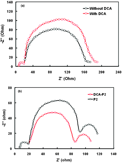 | ||
| Fig. 11 Nyquist plots of EIS for DSSCs with a modified TiO2 photoanode based on P2 sensitizers with and without DCA (a) in the dark (b) under illumination. | ||
To further improve the PCE of DSSCs sensitized with P2 dye using the modified photoanode, we have used DCA as a coadsorbent, to reduce molecular aggregation on the surface of TiO2. The J–V characteristics of the DSSC with DCA coadsorbent P2 dye are shown in Fig. 10 and the photovoltaic parameters are compiled in Table 5. The increase in PCE is mainly due to the enhanced value of Jsc. As we know, the aggregation of the dye could decrease the Jsc and the use of DCA could effectively suppress dye aggregation.51,52 When DCA is not introduced into the dye solution, rapid charge recombination between neighboring dye molecules occurs so that intramolecular charge separation may interfere due to the migration of excited state electrons.53 Such an enhanced spectral response, induced by the efficient intra-molecular charge separation and use of the coadsorbent, resulted in an enhancement in PCE.
Measurement of the EIS spectra of the DSSC based on DCA-P2 dye indicated that the fitted value of Rct for this DSSC is higher than that for P2 without DCA (Fig. 11). The higher Rct showed that the electron recombination process from the conduction band of TiO2 to the electrolyte slowed down, resulting in a higher Jsc value. The adsorbed amount of P2 dye on the TiO2 surface was also measured and was found to be lower than that for P2 without DCA. Despite this, the PCE is higher, indicating more efficient retardation of charge recombination, which is caused by the effective breakup of dye aggregation. The increased value of charge collection efficiency and electron diffusion length is also attributed to the enhanced value of PCE. The low value of Rtr for DSSC with DCA-P2, compared to that for P2, also suggests improved charge collection.
Conclusions
In conclusion, three porphyrin based dyes (P1, P2 and P3) with one, two and four pyridine rings as electron acceptor anchoring units were synthesized and characterized. The influence of the number of pyridine rings at the meso positions on the photovoltaic properties of the porphyrin sensitizers was investigated. The optimized DSSC based on the P2 sensitizer with a 12 μm TiO2 photoanode achieved a PCE of 3.9% with Jsc, Voc and FF values of 10.56 mA cm−2, 0.64 V and 0.60, respectively. This performance may be ascribed to a balance of efficient dye regeneration and electron injection processes, resulting from the suitable arrangement of the HOMO and LUMO energy levels in combination with the longest electron lifetime. We also demonstrated that the treatment of the TiO2 photoanode with formic acid (the modified photoanode) inherently facilitates more dye uptake, enhanced light harvesting, and charge collection efficiency leading to overall PCE up to 5.24% for the DSSC based on a P2 sensitizer. The PCE of the DSSC based on the modified photoanode improved up to 6.12% when DCA was added as a coadsorbent to the P2 solution. This improvement can be attributed to further enhancement in electron injection efficiency and charge collection efficiency.Acknowledgements
Financial support from the European Community's Seventh Framework Programme (FP7) under Grand Agreement No. 229927, project BIOSOLENUTI and Greek Secretariat of Research and Technology (Heraklitos) are gratefully acknowledged.References
- M. K. Nazeeruddin, A. Kay, I. Rodicio, R. Humphry-Baker, E. Mueller, P. Liska, N. Vlachopoulos and M. Grätzel, J. Am. Chem. Soc., 1993, 115, 6382–6390 CrossRef CAS.
- B. O'Regan and M. Grätzel, Nature, 1991, 353, 737–740 CrossRef CAS.
- M. Grätzel, Nature, 2001, 414, 338–344 CrossRef.
- M. Grätzel, Acc. Chem. Res., 2009, 42, 1788–1798 CrossRef.
- Q. Yu, Y. Wang, Z. Yi, N. Zu, J. Zhang, M. Zhang and P. Wang, ACS Nano, 2010, 4, 6032–6038 CrossRef CAS.
- C.-Y. Chen, M. Wang, J.-Y. Li, N. Pootrakulchote, L. Alibabaei, C.-h. Ngoc-le, J.-D. Decoppet, J.-H. Tsai, C. Grätzel, C.-G. Wu, S. M. Zakeeruddin and M. Grätzel, ACS Nano, 2009, 3, 3103–3109 CrossRef CAS.
- D. Kuang, C. Klein, S. Ito, J. E. Moser, R. Humphry-Baker, N. Evans, F. Duriaux, C. Grätzel, S. M. Zakeeruddin and M. Grätzel, Adv. Mater., 2007, 19, 1133–1137 CrossRef CAS.
- P. G. Bomben, K. C. D. Robson, B. D. Koivisto and C. P. Berlinguette, Coord. Chem. Rev., 2012, 256, 1438–1450 CrossRef CAS.
- A. Mishra, M. K. R. Fischer and P. Bäuerle, Angew. Chem., Int. Ed., 2009, 48, 2474–2499 CrossRef CAS.
- L.-Y. Lin, C.-H. Tsai, K.-T. Wong, T.-W. Huang, C.-C. Wu, S.-H. Chou, F. Lin, S.-H. Chen and A.-I. Tsai, J. Mater. Chem., 2011, 21, 5950–5958 RSC.
- C. Teng, X. Yang, C. Yang, H. Tian, S. Li, X. Wang, A. Hagfeldt and L. Sun, J. Phys. Chem. C, 2010, 114, 11305–11313 CAS.
- H. Tian, I. Bora, X. Jiang, E. Gabrielsson, K. M. Karlsson, A. Hagfeldt and L. Sun, J. Mater. Chem., 2011, 21, 12462–12472 RSC.
- D. Zhou, N. Cai, H. Long, M. Zhang, Y. Wang and P. Wang, J. Phys. Chem. C, 2011, 115, 3163–3171 CAS.
- M. Garcia-Iglesias, J.-J. Cid, J.-H. Yum, A. Forneli, P. Vazquez, M. K. Nazeeruddin, E. Palomares, M. Gratzel and T. Torres, Energy Environ. Sci., 2011, 4, 189–194 CAS.
- H. Imahori, T. Umeyama and S. Ito, Acc. Chem. Res., 2009, 42, 1809–1818 CrossRef CAS.
- W. M. Campbell, A. K. Burrell, D. L. Officer and K. W. Jolley, Coord. Chem. Rev., 2004, 248, 1363–1379 CrossRef CAS.
- X.-F. Wang and H. Tamiaki, Energy Environ. Sci., 2010, 3, 94–106 CAS.
- M. J. Griffith, K. Sunahara, P. Wagner, K. Wagner, G. G. Wallace, D. L. Officer, A. Furube, R. Katoh, S. Mori and A. J. Mozer, Chem. Commun., 2012, 48, 4145–4162 RSC.
- A. Hagfeldt, G. Boschloo, L. Sun, L. Kloo and H. Pettersson, Chem. Rev., 2010, 110, 6595–6663 CrossRef CAS.
- M. V. Martinez-Diaz, G. de la Torre and T. Torres, Chem. Commun., 2010, 46, 7090–7108 RSC.
- M. Ishida, S. W. Park, D. Hwang, Y. B. Koo, J. L. Sessler, D. Y. Kim and D. Kim, J. Phys. Chem. C, 2011, 115, 19343–19354 CAS.
- A. Yella, H.-W. Lee, H. N. Tsao, C. Yi, A. K. Chandiran, M. K. Nazeeruddin, E. W.-G. Diau, C.-Y. Yeh, S. M. Zakeeruddin and M. Grätzel, Science, 2011, 334, 629–634 CrossRef CAS.
- T. Bessho, S. M. Zakeeruddin, C.-Y. Yeh, E. W.-G. Diau and M. Grätzel, Angew. Chem., Int. Ed., 2010, 49, 6646–6649 CrossRef CAS.
- C.-L. Wang, Y.-C. Chang, C.-M. Lan, C.-F. Lo, E. Wei-Guang Diau and C.-Y. Lin, Energy Environ. Sci., 2011, 4, 1788–1795 CAS.
- Y. Ooyama, S. Inoue, T. Nagano, K. Kushimoto, J. Ohshita, I. Imae, K. Komaguchi and Y. Harima, Angew. Chem., Int. Ed., 2011, 50, 7429–7433 CrossRef CAS.
- Y. Ooyama, T. Nagano, S. Inoue, I. Imae, K. Komaguchi, J. Ohshita and Y. Harima, Chem.–Eur. J., 2011, 17, 14837–14843 CrossRef CAS.
- M. K. Panda, G. D. Sharma, K. R. Justin Thomas and A. G. Coutsolelos, J. Mater. Chem., 2012, 22, 8092–8102 RSC.
- J. R. S. Brownson, M. I. Tejedor-Tejedor and M. A. Anderson, J. Phys. Chem. B, 2006, 110, 12494–12499 CrossRef CAS.
- M. J. T. Frisch, G. W. Trucks, H. B. Schlegel, G. E. Scuseria, M. A. Robb, J. R. Cheeseman, J. A. Montgomery Jr., T. Vreven, K. N. Kudin, J. C. Burant, J. M. Millam, S. S. Iyengar, J. Tomasi, V. Barone, B. Mennucci, M. Cossi, G. Scalmani, N. Rega, G. A. Petersson, H. Nakatsuji, M. Hada, M. Ehara, K. Toyota, R. Fukuda, J. Hasegawa, M. Ishida, T. Nakajima, Y. Honda, O. Kitao, H. Nakai, M. Klene, X. Li, J. E. Knox, H. P. Hratchian, J. B. Cross, V. Bakken, C. Adamo, J. Jaramillo, R. Gomperts, R. E. Stratmann, O. Yazyev, A. J. Austin, R. Cammi, C. Pomelli, J. W. Ochterski, P. Y. Ayala, K. Morokuma, G. A. Voth, P. Salvador, J. J. Dannenberg, V. G. Zakrzewski, S. Dapprich, A. D. Daniels, M. C. Strain, O. Farkas, D. K. Malick, A. D. Rabuck, K. Raghavachari, J. B. Foresman, J. V. Ortiz, Q. Cui, A. G. Baboul, S. Clifford, J. Cioslowski, B. B. Stefanov, G. Liu, A. Liashenko, P. Piskorz, I. Komaromi, R. L. Martin, D. J. Fox, T. Keith, M. A. Al-Laham, C. Y. Peng, A. Nanayakkara, M. Challacombe, P. M. W. Gill, B. Johnson, W. Chen, M. W. Wong, C. Gonzalez and J. A. Pople, Gaussian 09, A.02, 2009 Search PubMed.
- G. Scalmani and M. J. Frisch, J. Chem. Phys., 2010, 132, 114110–114115 CrossRef.
- A. D. Adler, F. R. Longo, J. D. Finarelli, J. Goldmacher, J. Assour and L. Korsakoff, J. Org. Chem., 1967, 32, 476–476 CrossRef CAS.
- T. Gianferrara, D. Giust, I. Bratsos and E. Alessio, Tetrahedron, 2007, 63, 5006–5013 CrossRef CAS.
- W. Zhou, B. Zhao, P. Shen, S. Jiang, H. Huang, L. Deng and S. Tan, Dyes Pigm., 2011, 91, 404–412 CrossRef CAS.
- G. Zhang, H. Bala, Y. Cheng, D. Shi, X. Lv, Q. Yu and P. Wang, Chem. Commun., 2009, 2198–2200 RSC.
- C.-F. Lo, S.-J. Hsu, C.-L. Wang, Y.-H. Cheng, H.-P. Lu, E. W.-G. Diau and C.-Y. Lin, J. Phys. Chem. C, 2010, 114, 12018–12023 CAS.
- G. Li, K.-J. Jiang, P. Bao, Y.-F. Li, S.-L. Li and L.-M. Yang, New J. Chem., 2009, 33, 868–876 RSC.
- The Porphyrin Handbook, ed. K. M. Kadish, K. M. Smith and R. Guilard, Academic Press, London, 2000, vol. 6 Search PubMed.
- W. M. Campbell, K. W. Jolley, P. Wagner, K. Wagner, P. J. Walsh, K. C. Gordon, L. Schmidt-Mende, M. K. Nazeeruddin, Q. Wang, M. Grätzel and D. L. Officer, J. Phys. Chem. C, 2007, 111, 11760–11762 CAS.
- (a) J. B. Peri, Catalysis: Science and Technology, ed. J. R. Anderson and M. Boudart, Springer, Berlin, 1984, vol. 5, pp. 171–220 Search PubMed; (b) A. A. Davydov, in Infrared Spectroscopy of Adsorbed Species on the Surface of Transition Metal Oxide, ed. C. H. Rochester, Wiley, Chichester, 1984 Search PubMed; (c) M. I. Zaki, M. A. Hasan, F. A. Al-Sagheer and L. Pasupulety, Colloids Surf., A, 2001, 190, 261 CrossRef CAS; (d) V. Vishwanathan, H.-S. Roh, J.-W. Kim and K.-W. Jun, Catal. Lett., 2004, 96, 23 CrossRef CAS.
- K.-M. Lee, V. Suryanarayanan and K.-C. Ho, Sol. Energy Mater. Sol. Cells, 2006, 90, 2398–2404 CrossRef CAS.
- J.-G. Chen, C.-Y. Chen, S.-J. Wu, J.-Y. Li, C.-G. Wu and K.-C. Ho, Sol. Energy Mater. Sol. Cells, 2008, 92, 1723–1727 CrossRef CAS.
- T. Miyasaka, M. Ikegami and Y. Kijitori, J. Electrochem. Soc., 2007, 154, A455–A461 CrossRef CAS.
- G. Schlichthörl, S. Y. Huang, J. Sprague and A. J. Frank, J. Phys. Chem. B, 1997, 101, 8141–8155 CrossRef.
- Q. Wang, J.-E. Moser and M. Grätzel, J. Phys. Chem. B, 2005, 109, 14945–14953 CrossRef CAS.
- B. Lee, D.-K. Hwang, P. Guo, S.-T. Ho, D. B. Buchholtz, C.-Y. Wang and R. P. H. Chang, J. Phys. Chem. B, 2010, 114, 14582–14591 CrossRef CAS.
- Y.-D. Lin and T. J. Chow, J. Mater. Chem., 2011, 21, 14907–14916 RSC.
- S.-Q. Fan, C. Kim, B. Fang, K.-X. Liao, G.-J. Yang, C.-J. Li, J.-J. Kim and J. Ko, J. Phys. Chem. C, 2011, 115, 7747–7754 CAS.
- J. Bisquert, Phys. Chem. Chem. Phys., 2003, 5, 5360–5364 RSC.
- G. D. Sharma, P. Suresh and J. A. Mikroyannidis, Electrochim. Acta, 2010, 55, 2368–2372 CrossRef CAS.
- S. H. Kang, S. H. Choi, M. S. Kang, J. Y. Kim, H. S. Kim, T. Hyeon and Y. E. Sung, Adv. Mater., 2008, 20, 54–58 CrossRef CAS.
- K. D. Seo, H. M. Song, M. J. Lee, M. Pastore, C. Anselmi, F. De Angelis, M. K. Nazeeruddin, M. Gräetzel and H. K. Kim, Dyes Pigm., 2011, 90, 304–310 CrossRef CAS.
- B. J. Song, H. M. Song, I. T. Choi, S. K. Kim, K. D. Seo, M. S. Kang, M. J. Lee, D. W. Cho, M. J. Ju and H. K. Kim, Chem.–Eur. J., 2011, 17, 11115–11121 CrossRef CAS.
- H. M. Song, K. D. Seo, M. S. Kang, I. T. Choi, S. K. Kim, Y. K. Eom, J. H. Ryu, M. J. Ju and H. K. Kim, J. Mater. Chem., 2012, 22, 3786–3794 RSC.
| This journal is © The Royal Society of Chemistry 2012 |

