Fabrication of visible/near-IR antireflective and superhydrophobic coatings from hydrophobically modified hollow silica nanoparticles and poly(methyl methacrylate)†
Ligang
Xu
ab,
Liangjuan
Gao
ab and
Junhui
He
*a
aFunctional Nanomaterials Laboratory and Key Laboratory of Photochemical Conversion and Optoelectronic Materials, Technical Institute of Physics and Chemistry, Chinese Academy of Sciences, Zhongguancundonglu 29, Haidianqu, Beijing 100190, China. E-mail: jhhe@mail.ipc.ac.cn; Fax: +86 10 82543535
bGraduate University of the Chinese Academy of Sciences, Beijing 100049, China
First published on 2nd November 2012
Abstract
A facile dip-coating approach was developed to fabricate visible/near-IR antireflective and superhydrophobic coatings on glass substrates from hydrophobic hexamethyldisilazane (HMDS)-modified hollow silica nanoparticles (HMDS–HSNs) and poly(methyl methacrylate) (PMMA). While the coated glass substrates showed greatly enhanced transmittance in the visible/near-IR range as compared with uncoated glass substrates, water droplets could roll easily and quickly off the coated surfaces. For the coating prepared using a suspension of 1.00 wt% PMMA and 0.50 wt% HMDS–HSNs, the water contact angle (WCA) of the coating was as high as 163° with a sliding angle (SA) of ≤1°, and the coated glass substrate showed excellent antireflection in the visible/near-IR spectral range with a maximum transmittance of 92.6%. The average transmittance of the coated glass substrate increased to 91.5% as compared to that of the uncoated glass substrate (88.2%) in the spectral range of 573–2500 nm. In particular, in the spectral range of 850–1200 nm, the coated glass substrate (ca. 91%) exhibited an increase of nearly 5% in transmittance as compared with the uncoated glass substrate (ca. 86%). Scanning electron microscopy (SEM), transmission electron microscopy (TEM) and atomic force microscopy (AFM) were used to observe the morphology and structure of the nanoparticles and the coated surfaces. The effects of PMMA and HMDS–HSN concentrations were also discussed on the basis of experimental observations.
Introduction
Superhydrophobic surfaces, exhibiting a water contact angle (WCA) higher than 150° and a sliding angle (SA) lower than 10°,1,2 have promising applications in self-cleaning,1 anticorrosion,3 and improving blood compatibility,4etc.5 High surface roughness and low surface energy are the prerequisites to achieving superhydrophobicity, as shown by many natural and artificial superhydrophobic objects. In general, micro- and nanoscale hierarchical structures with a hydrophobic top surface are employed to achieve superhydrophobicity.6 Nanoparticles are frequently used to fabricate superhydrophobic surfaces because of their controllable size and structure and easy synthesis.7On the other hand, antireflection has received much attention in the past few decades due to its underlying relationship to structure, and wide potential applications.8 In particular, antireflection near-infrared optics can be used for night vision, sensors, cancer detection, body scanning and hot-spot detection.9 In simple cases, antireflective coatings can effectively enhance the transmission of light because of the destructive interference between light reflected from the coating–substrate and the air–coating interfaces. An antireflective coating of a quarter-wavelength optical thickness in the visible region should satisfy the conditions of low surface roughness and low refractive index.10
Hydrophobicity and transparency are well known to be competitive properties. When roughness increases, hydrophobicity increases, whereas transparency decreases.11 Therefore, it is currently still a technical challenge to simultaneously achieve both superhydrophobicity and antireflection by an easy and cost-effective method. As a result, the practical application of superhydrophobic coatings has so far been limited to optically transparent materials (such as solar cell glass panels) that require dual-function (superhydrophobicity and antireflection) coatings. Hollow silica nanoparticles with lower refractive indices than solid silica nanoparticles have previously been used to fabricate transparent and superhydrophobic coatings.12
Combinatorial methods have been applied extensively in inorganic chemistry, mainly for thin-film depositions. Scientists have used combinatorial methods in an attempt to optimize the functional properties of a range of materials, such as bandgap, ferro/di-electric, fuel cell anode/cathode properties and so on.13 In this work, we used combinatorial methods to fabricate visible/near-IR antireflective and superhydrophobic coatings on glass substrates from hydrophobically modified hollow silica nanoparticles and poly(methyl methacrylate) via dip-coating. This approach is simple and might be used for a large scale fabrication of bi-functional coatings.
Experimental methods
Materials
Tetraethyl orthosilicate (TEOS, 98+%), hexamethyldisilazane (HMDS, 98%), poly(methyl methacrylate) (PMMA, Mw = 32![[thin space (1/6-em)]](https://www.rsc.org/images/entities/char_2009.gif) 000) and 1H,1H,2H,2H-perfluorooctyltriethoxysilane (POTS, 97%) were obtained from Alfa Aesar. Aqueous ammonia (25%), absolute ethanol (99.5%) and ethyl acetate (98%) were purchased from Beihua Fine Chemicals. Poly(acrylic acid) (PAA, Mw = 5000, 30 wt% in water) was obtained from Shandong Heli water treatment company. Ultrapure water with a resistivity higher than 18.2 MΩ cm was used in all experiments, and was obtained from a three-stage Millipore Mill-Q Plus 185 purification system (Academic).
000) and 1H,1H,2H,2H-perfluorooctyltriethoxysilane (POTS, 97%) were obtained from Alfa Aesar. Aqueous ammonia (25%), absolute ethanol (99.5%) and ethyl acetate (98%) were purchased from Beihua Fine Chemicals. Poly(acrylic acid) (PAA, Mw = 5000, 30 wt% in water) was obtained from Shandong Heli water treatment company. Ultrapure water with a resistivity higher than 18.2 MΩ cm was used in all experiments, and was obtained from a three-stage Millipore Mill-Q Plus 185 purification system (Academic).
Preparation of HMDS modified hollow silica nanoparticles
In a typical procedure, 0.40 g of PAA dissolved in 4.5 mL of aqueous ammonia was mixed with 90 mL of absolute ethanol, followed by the injection of 5 aliquots of TEOS totaling 1.80 mL over a time interval of 1 h under vigorous magnetic stirring at room temperature. After 10 h, 45 nm hollow silica nanoparticles were formed. Then a certain quantity of HMDS (the molar ratio of HMDS to TEOS was 0.9) was added to the sol with stirring, and stirred for a further 1 day. The sols needed to settle for at least 8 h. The samples were washed by repeated centrifugation (10![[thin space (1/6-em)]](https://www.rsc.org/images/entities/char_2009.gif) 000 rpm, 20 min)/re-dispersion (in ethanol) three times, and then oven dried at 25 °C overnight.
000 rpm, 20 min)/re-dispersion (in ethanol) three times, and then oven dried at 25 °C overnight.
Dip-coating and hydrophobic modified
Poly(methyl methacrylate) (PMMA, Mw = 32![[thin space (1/6-em)]](https://www.rsc.org/images/entities/char_2009.gif) 000) was dissolved in ethyl acetate to prepare a stock solution. An appropriate amount of HMDS-modified hollow silica nanoparticles was mixed with the polymer solution, and the mixture was subsequently stirred vigorously for an additional 12 h. A clean glass substrate was immersed into the suspension mixture for 5 min before withdrawal for the first dip-coating and for 5 s before withdrawal for four subsequent dip-coatings. After each dip-coating, the substrate was dried for 2 min at room temperature (25 °C). The withdrawal speed was kept at 8 cm min−1. An antireflective and superhydrophobic coating was finally obtained by chemical vapor deposition (CVD) of a layer of 1H,1H,2H,2H-perfluorooctyltriethoxysilane (POTS). The coated slide glass was then placed in a Teflon container, and sealed in a stainless steel autoclave on the bottom of which was dispensed a few droplets (10–20 μL) of POTS. There was no direct contact between the substrate and the POTS droplets. The autoclave was put in an oven at 120 °C for 2 h to enable the vapor of the POTS to react with the hydroxyl groups on the coating surface. Finally, the autoclave was opened and placed in an oven at 150 °C for an additional 1.5 h to volatilize the unreacted POTS molecules on the coating.
000) was dissolved in ethyl acetate to prepare a stock solution. An appropriate amount of HMDS-modified hollow silica nanoparticles was mixed with the polymer solution, and the mixture was subsequently stirred vigorously for an additional 12 h. A clean glass substrate was immersed into the suspension mixture for 5 min before withdrawal for the first dip-coating and for 5 s before withdrawal for four subsequent dip-coatings. After each dip-coating, the substrate was dried for 2 min at room temperature (25 °C). The withdrawal speed was kept at 8 cm min−1. An antireflective and superhydrophobic coating was finally obtained by chemical vapor deposition (CVD) of a layer of 1H,1H,2H,2H-perfluorooctyltriethoxysilane (POTS). The coated slide glass was then placed in a Teflon container, and sealed in a stainless steel autoclave on the bottom of which was dispensed a few droplets (10–20 μL) of POTS. There was no direct contact between the substrate and the POTS droplets. The autoclave was put in an oven at 120 °C for 2 h to enable the vapor of the POTS to react with the hydroxyl groups on the coating surface. Finally, the autoclave was opened and placed in an oven at 150 °C for an additional 1.5 h to volatilize the unreacted POTS molecules on the coating.
Characterization
Transmission spectra in the wavelength range of 200–2500 nm were recorded using a Varian Cary 5000 UV/Vis-NIR spectrophotometer. The as-prepared coatings were examined by scanning electron microscopy (SEM) on a Hitachi S-4300 scanning electron microscope operated at 10 kV. The specimens were coated with a layer of gold by ion sputtering before the SEM observations. For transmission electron microscopy (TEM) observations, the sols were diluted by ethanol without violent stirring or vibration to avoid possible damage to the colloidal aggregation, and put onto carbon-coated copper grids. After drying at 60 °C overnight, they were observed using a JEOL JEM-2100F transmission electron microscope at an acceleration voltage of 200 kV. Water contact angles (WCAs) of the coating surfaces were measured at ambient temperature on a JC2000C contact angle/interface system (Shanghai Zhongchen Digital Technique Apparatus Co.). The angle precision was ±0.5°. Water droplets of 4 μL were dropped carefully onto the coating surfaces. The roughness and morphology of the coating surfaces were characterized by atomic force microscopy (AFM) on a MM8-SYS Scanning Probe Microscope (Bruker AXR).Results and discussion
Synthesis of hollow silica nanoparticles and modified hollow silica nanoparticles
Hollow silica nanoparticles (HSNs) were prepared according to a method developed by Yu's group.14 The surfaces of the resulting hollow silica nanoparticles with a diameter of 45.1 ± 8.6 nm and a shell thickness of 12.0 ± 2.7 nm were modified with hexamethyldisilazane (HMDS).Fig. 1a and b show transmission electron microscopy (TEM) images of the HSNs and HMDS–HSNs, respectively. Clearly, the HSNs are highly dispersed, but their is a wide distribution of sizes. After HMDS modification, the HMDS–HSNs show a clear trend to aggregate and can be easily dispersed in ethyl acetate to form a suspension. The surfaces of the HSNs are covered by methyl groups due to the HMDS modification,7b which apparently lowers the surface energy.
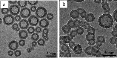 | ||
| Fig. 1 TEM images of HSNs (a) and HMDS–HSNs (b). | ||
Surface structure and morphology of coatings
Given amounts of PMMA and HMDS–HSNs were dissolved/dispersed in ethyl acetate to prepare a suspension mixture. The suspension mixture was then dip-coated onto pre-cleaned glass substrates followed by solvent evaporation, resulting in the formation of an appropriately rough surface.Scanning electron microscopy (SEM) images of the coating prepared from 0.50 wt% of HMDS–HSN and 1.00 wt% of PMMA after POTS treatment are shown in Fig. 2a and b. Clearly, the glass substrate was homogeneously covered without any uncoated areas (Fig. 2a). A magnified image (Fig. 2b) shows, however, that the surface of the coating was in fact very rough and the HSNs aggregated, leaving nanoridges (indicated by the arrow) and nanovalleys (indicated by the dashed arrow). The coating could be clearly recognized in the cross-sectional SEM image as shown in Fig. 2c. The coating has a thickness of ca. 140 nm, and one nanoridge is seen to protrude from the coating surface. The AFM images in Fig. S1b and g (ESI†) again show that the glass substrate is fully covered by hollow silica nanoparticles and that there are several nanoridges (indicated by the white arrows) and nanovalleys (indicated by the white dashed arrows) on the surface. The RMS roughness of the surface was estimated to be ca. 39 nm from an area of 10 μm × 10 μm. Thus, hollow silica nanoparticle–polymer nanocomposite coatings were successfully fabricated by the dip-coating process, which is simple and feasible for large area applications.
 | ||
| Fig. 2 Top-view (a, b) and cross-sectional view (c) SEM images of the coating dip-coated from a suspension containing 0.5 wt% of HMDS–HSN and 1.0 wt% of PMMA after POTS treatment. (b) is the magnified image of (a). | ||
Effect of PMMA concentration on optical and wetting properties of the coating
The optical and wetting properties were found to be affected by the PMMA concentration in the dip-coating suspension. When the HMDS–HSN concentration was fixed at 0.50 wt% in the suspension, the optical and wetting properties of the coatings significantly changed with an increase in the PMMA concentration. Fig. 3a shows the transmission spectra of several coated glass substrates in comparison with that of the uncoated glass substrate. The uncoated glass substrate has a maximum transmittance of 91.4% at a wavelength of 512 nm, but significantly lower transmittance in the visible/near-IR spectral range. The lowest transmittance occurs at 1085 nm and was estimated to be 85.6%. For the coated substrates, however, greatly enhanced transmittance was observed in this visible/near-IR spectral range. With increasing PMMA concentration, the maximum transmittance decreases, while the transmittance in the near-IR spectral range first increases and then decreases. For the first of these observations, the reason might be that the refractive index of the coating increases with increasing PMMA concentration. The coating dip-coated from a suspension containing 0.50 wt% of HMDS–HSN and 1.00 wt% of PMMA has excellent antireflection properties in the near-IR spectral range, though its maximum transmittance is 92.6% at a wavelength of 690 nm. In the spectral range of 573–2500 nm, the average transmittance of the coated glass increases to 91.5% as compared to that of the uncoated glass substrate (88.2%), showing excellent broad band antireflection in the visible/near-IR spectral range. In particular, in the spectral range of 850–1200 nm, the coated glass substrate (ca. 91%) has an increase of nearly 5% in transmittance as compared with the uncoated glass substrate (ca. 86%).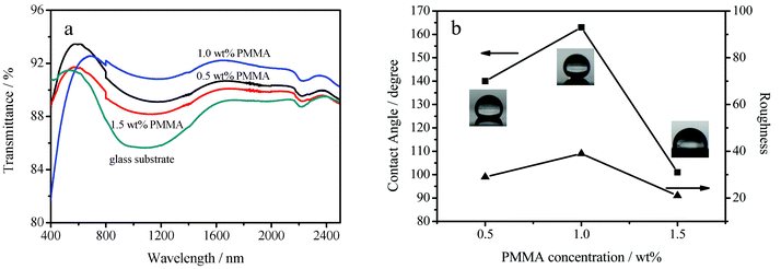 | ||
| Fig. 3 (a) Transmission spectra of the glass substrate and the glass substrates dip-coated in suspensions containing 0.50 wt% of HMDS–HSN with 0.50 wt% of PMMA, 1.00 wt% of PMMA and 1.50 wt% of PMMA, respectively. (b) WCAs of 4 μL water droplets (■) on, and surface roughnesses (▲) of, surfaces dip-coated in suspensions with various concentrations of PMMA. | ||
The wettability of the coating surfaces after POTS modification was characterized by contact angle and sliding angle measurements using water droplets of 4 μL. As shown in Fig. 3b, the water contact angle (WCA) was also affected by the PMMA concentration. For PMMA concentrations of 0.50, 1.00 and 1.50 wt%, the WCAs were 140 ± 2, 163 ± 2, and 101 ± 2°, respectively. The AFM images in Fig. S1a, b and c (ESI†) also show that the roughness of the coatings changed significantly as the PMMA concentration increased, so the WCAs changed correspondingly. The root-mean square (RMS) roughness was estimated on an area of 10 × 10 μm (Fig. S1f, g and i, ESI†). It changed from 29 nm to 39 nm to 21 nm when the PMMA concentration increased from 0.50 wt% to 1.00 wt% to 1.50 wt%. Fig. 3b shows that the WCA changed in accordance with the surface roughness, indicating that the surface roughness played a key role in determining the surface wettability of the coatings. For the PMMA concentration of 1.00 wt%, the coating exhibited superhydrophobicity, and the sliding angle was as low as 1° (Fig. S2, ESI†). The low sliding angle guarantees that water droplets on the surface can roll off easily and makes the surface self-cleaning. In contrast, the water contact angle on the surface without POTS treatment was only 137° ± 2° (Fig. S3, ESI†). Clearly, the surface energy plays a vital role in the wettability of the coating, and the additional surface modification by low surface energy POTS is indispensable for making the surface highly superhydrophobic. The superhydrophobicity is also attributed to the surface roughness derived from nanoridges and nanovalleys on the coating surface (Fig. 2 and Fig. S1b and g, ESI†). When a water droplet is placed on the coating surface, the nanoridges and nanovalleys can result in a discontinuation of the contact area between the water and the coating surface as in the case of Cassie's model.15 A high WCA was thus observed, and the adhesion force between the substrate and the water droplet was very small and could be neglected.
The coating prepared from a suspension containing 0.50 wt% of HMDS–HSN and 1.00 wt% of PMMA after POTS treatment showed both superhydrophobicity and excellent transmittance. The digital images of the glass substrate with the superhydrophobic coating are shown in Fig. 4 and 5. Fig. 4 shows that the water droplets looked like transparent spheres, suggesting high WCAs. The letters under the coated slide glass were clearly visible, showing its excellent transparency. From Fig. 5, it can be seen that the coated area was russet with low reflectivity towards a fluorescent lamp. In contrast, the uncoated area was white with high reflectivity.
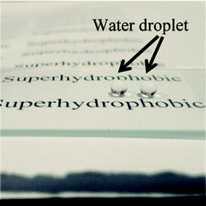 | ||
| Fig. 4 Digital image of a glass substrate with both sides covered with an antireflective and superhydrophobic coating dip-coated from a suspension containing 0.5 wt% of HMDS–HSN and 1.0 wt% of PMMA after POTS treatment. | ||
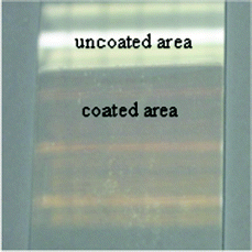 | ||
| Fig. 5 Digital image of the interface reflection towards a fluorescent lamp for an uncoated area (upper part) and coated area (lower part) of the surface with an antireflective and superhydrophobic coating. The antireflective and superhydrophobic coating was fabricated by dip-coating the glass substrate in a suspension containing 0.5 wt% of HMDS–HSN and 1.0 wt% of PMMA followed by POTS modification. | ||
Effect of HMDS–HSN concentration on the optical and wetting properties of the coating
The HMDS–HSN concentration was also found to strongly affect the optical and wetting properties of the coatings. Coatings were prepared using dip-coating suspensions of various HMDS–HSN concentrations (0.25 wt%, 0.50 wt% and 0.75 wt%) while the PMMA concentration was fixed at 1.00 wt%. The transmission spectra of the coated glasses in the UV-visible-near IR wavelength range are shown in Fig. 6a. When the suspension contained 0.25 wt% of HMDS–HSN, the coated glass substrate had a lower maximum transmittance (90.7%) at 507 nm as compared to the uncoated glass substrate (91.4% at 512 nm) in the UV-visible wavelength range, but enhanced transmittance in the near-IR wavelength range. When the HMDS–HSN concentration was increased to 0.50 wt%, the maximum transmittance increased to 92.8%, and the coated glass substrate showed enhanced transmittance even in the near-IR wavelength range, which results in excellent antireflection properties. However, the transmittance decreases with a further increase of the HMDS–HSN concentration with a maximum transmittance of 91.7% at 727 nm in the UV-visible wavelength range, but excellent antireflection is retained in the near-IR wavelength range.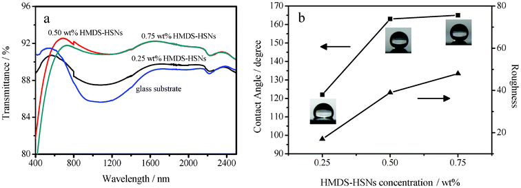 | ||
| Fig. 6 (a) Transmission spectra of the glass substrate and glass substrates dip-coated in suspensions containing 1.00 wt% of PMMA with 0.25 wt% of HMDS–HSN, 0.50 wt% HMDS–HSN and 0.75 wt% HMDS–HSN, respectively. (b) WCAs of 4 μL water droplets (■) on, and surfaces roughnesses (▲) of, surfaces dip-coated in suspensions having various concentrations of HMDS–HSN. | ||
As shown in Fig. 6b, for the HMDS–HSN concentrations of 0.25 wt%, 0.50 wt% and 0.75 wt%, the WCAs were 122 ± 2°, 163 ± 2°, and 165 ± 2°, respectively. These observations may be related to the surface roughness of the coatings. In fact, from Fig. S1 g, i and j (ESI†), it can be seen clearly that the surface changed from smooth to striate gradually and the RMS roughness increased from 17 nm to 39 nm to 48 nm as the HMDS–HSN concentration is increased from 0.25 wt% to 0.50 wt% to 0.75 wt%. Fig. 6b shows that the WCA increased in accordance with the surface roughness, again indicating that the surface roughness played a key role in determining the surface wettability of the coatings. Therefore the transparency first increased and then slightly decreased but the hydrophobicity monotonically increased as the HMDS–HSN concentration increased.
Theoretical analysis of the refractive index of the antireflective coating
If a coating with thickness dc can reach zero reflection, the refractive index of the coating should satisfy the following conditions: dc = λ/4nc, where λ is the wavelength of the incident light, and nc is the refractive index of the coating; nc = (nans)1/2, where na and ns are the refractive indices of air and the substrate, respectively. The value of na is nearly 1, and ns for the glass substrate is ∼1.5. Thus the value of nc must be ca. 1.23 to reach zero reflection.11aThe single surface reflectance of the substrate can be described by eqn (1):
| Rs = (ns − 1)2/(ns + 1)2 | (1) |
| R = (nbulk − 1)2/(nbulk + 1)2 | (2) |
| nbulk = nc2/ns | (3) |
Thus, the following equation (eqn (4)) applies:
| R = (nc2/ns − 1) 2/(nc2/ns + 1)2 | (4) |
The refractive indices of coated glass and uncoated glass were calculated using eqn (2) and eqn (1), as previously reported.17 It must be noted that R in the equations is the single surface reflectance. The reflectance can be calculated from the transmittance (T) if the absorption is neglected, i.e., Rdouble = 1 − T, which is caused by both surfaces. According to eqn (2), R = Rdouble/2 = (nbulk − 1)2/(nbulk + 1)2 and nbulk can thus be calculated.
Fig. 7 shows the dependence of the calculated refractive index of the coated glass (nbulk) (coating prepared using a suspension containing 0.50 wt% of HMDS–HSN and 1.00 wt% of PMMA) and uncoated glass (ns) on the wavelength (λ) of the incident light. Clearly, the calculated refractive index of the coated glass is lower than that of the glass substrate in the wavelength range of 573–2500 nm, but higher than that of the glass substrate in the wavelength range of 400–573 nm. This is in good agreement with the observation that the coating has a higher transmittance in the wavelength range of 573–2500 nm, but lower transmittance in the wavelength range of 400–573 nm, as compared to the glass substrate. When λ is 675 nm, the reflection of the coated glass is at a minimum (Rmin = 3.6%). As ns and nbulk are 1.56 and 1.48 at 675 nm, respectively, nc was calculated as 1.52 using eqn (3). When λ is 1050 nm, the coated glass (ca. 91%) exhibits an increase of nearly 5.3% in transmittance as compared with the glass substrate (ca. 85.7%), and the corresponding calculated refractive indices are 1.54 (coated glass) and 1.73 (glass substrate). It is known that a gradual change in the refractive index from air to the substrate is crucial for surface antireflective properties.18 For the glass substrate, the refractive index changes sharply from 1.0 to 1.73 (at 1050 nm) across the air/glass substrate interface, resulting in high reflection and low transmission (Fig. 3a). However, for the glass substrate with the coating, the refractive index changes from 1.0 to 1.54, i.e., a smaller change, leading to decreased reflection and enhanced transmission (Fig. 3a).
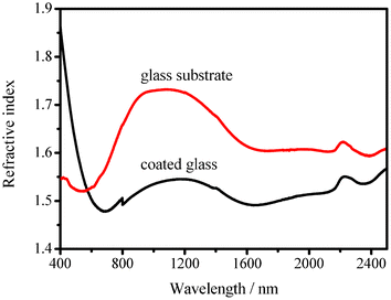 | ||
| Fig. 7 Dependence on the wavelength of the incident light of the refractive index of the glass substrate and the glass substrate dip-coated in a suspension containing 0.50 wt% of HMDS–HSN and 1.00 wt% of PMMA. | ||
Hollow silica nanoparticles play two important roles in the construction of superhydrophobic and visible/near-IR antireflective coatings. First, they have a wide distribution of sizes, and after modification by HMDS, they are partially aggregated, which allows for easy fabrication of coatings with sufficient roughness to achieve excellent superhydrophobicity after POTS modification. Second, the HSNs with an interior (air) with a low refractive index could significantly lower the apparent refractive index of coatings as compared with solid silica nanoparticles, and thus significantly suppress light reflection and enhance light transmission, making the coatings highly transparent.
Conclusions
In summary, we have developed a simple and effective approach to fabricate visible/near-IR antireflective and superhydrophobic coatings on glass substrates via dip-coating in hydrophobically modified hollow silica nanoparticle–poly(methyl methacrylate) suspensions. After modification of the coatings by chemical vapor deposition of 1H,1H,2H,2H-perfluorooctyltrimethoxysilane, the coatings showed not only excellent superhydrophobicity, but also significant broad band antireflection in the visible/near-IR spectral range. For the coating prepared using a suspension of 1.00 wt% of PMMA and 0.50 wt% of HMDS–HSN, the water contact angle (WCA) of the coating reached as high as 163° with a sliding angle (SA) of ≤1°, and the coated glass substrate showed excellent antireflection properties in the visible/near-IR spectral range with a maximum transmittance of 92.6%. The average transmittance of the coated glass substrate increased to 91.5% as compared to that of the uncoated glass substrate (88.2%) in the spectral range of 573–2500 nm. In particular, in the spectral range of 850–1200 nm, the coated glass substrate (ca. 91%) exhibited an increase of nearly 5% in transmittance as compared with the uncoated glass substrate (ca. 86%). The effects of PMMA and HMDS–HSN concentration were also discussed on the basis of the experimental observations. The current work may open a new approach to dual-function coatings exhibiting visible/near-IR antireflection and superhydrophobicity, which may have a wide range of applications, such as solar energy conversion, night vision, sensors, cancer detection and treatment, body scanning, and hot-spot detection.Acknowledgements
This work was supported by the National High Technology Research and Development Program (“863” Program) of China (Grant No. 2011AA050525), the Knowledge Innovation Program of the Chinese Academy of Sciences (CAS) (Grant Nos. KGCX2-YW-370, KGCX2-EW-304-2) and the “Hundred Talents Program” of the CAS. We are very grateful to Ms. Lin Yao for helpful discussions.References
- X. Gao and L. Jiang, Nature, 2004, 432, 36–36 CrossRef CAS.
- Q. Xie, J. Xu, L. Feng, L. Jiang, W. Tang, X. Luo and C. C. Han, Adv. Mater., 2004, 16, 302–305 CrossRef CAS.
- Y. Zhu, J. Zhang, Y. Zheng, Z. Huang, L. Feng and L. Jiang, Adv. Funct. Mater., 2006, 16, 568–574 CrossRef CAS.
- T. Sun, H. Tan, D. Han, Q. Fu and L. Jiang, Small, 2005, 1, 959–964 CrossRef CAS.
- (a) W. Song, A. C. Lima and J. F. Mano, Soft Matter, 2010, 6, 5868–5871 RSC; (b) Y. Jiang, P. Wan, M. Smet, Z. Wang and X. Zhang, Adv. Mater., 2008, 20, 1972–1977 CrossRef CAS; (c) Z. Guo, W. Liu and B.-L. Su, J. Colloid Interface Sci., 2011, 353, 335–355 CrossRef CAS; (d) F. Celestini, R. Kofman, X. Noblin and M. Pellegrin, Soft Matter, 2010, 6, 5872–5876 RSC.
- (a) H. Wang, J. Fang, T. Cheng, J. Ding, L. Qu, L. Dai, X. Wang and T. Lin, Chem. Commun., 2008, 877–879 RSC; (b) S. Hu, X. Cao, Y. Song, C. Li, P. Xie and L. Jiang, Chem. Commun., 2008, 2025–2027 RSC; (c) X. Zhang, F. Shi, J. Niu, Y. Jiang and Z. Wang, J. Mater. Chem., 2008, 18, 621–633 RSC; (d) Q. F. Xu, J. N. Wang, I. H. Smith and K. D. Sanderson, J. Mater. Chem., 2009, 19, 655–660 RSC; (e) Y. Zhu, J. C. Zhang, J. Zhai, Y. M. Zheng, L. Feng and L. Jiang, ChemPhysChem, 2006, 7, 336–341 CrossRef CAS.
- (a) R. G. Karunakaran, C.-H. Lu, Z. Zhang and S. Yang, Langmuir, 2009, 25, 4594–4601 Search PubMed; (b) X. Li and J. Shen, Chem. Commun., 2011, 47, 10761–10763 RSC; (c) X. Liu and J. He, J. Phys. Chem. C, 2008, 113, 148–152 CrossRef; (d) X. Du, X. Li and J. He, ACS Appl. Mater. Interfaces, 2010, 2, 2365 CrossRef CAS; (e) Y. Li, F. Liu and J. Sun, Chem. Commun., 2009, 2730–2732 RSC.
- (a) S. Walheim, E. Schäffer, J. Mlynek and U. Steiner, Science, 1999, 283, 520–522 CrossRef CAS; (b) H. Hattori, Adv. Mater., 2001, 13, 51–54 CrossRef CAS; (c) J. A. Hiller, J. D. Mendelsohn and M. F. Rubner, Nat. Mater., 2002, 1, 59–63 CrossRef CAS; (d) X. Du and J. He, Chem.–Eur. J., 2011, 17, 8165–8174 CrossRef CAS; (e) L. Xu and J. He, ACS Appl. Mater. Interfaces, 2012, 4, 3293–3299 CrossRef CAS.
- K. C. Camargo, A. F. Michels, F. S. Rodembusch and F. Horowitz, Chem. Commun., 2012, 48, 4992–4994 RSC.
- B. E. Yoldas, Appl. Opt., 1980, 19, 1425–1429 CrossRef CAS.
- (a) J. Bravo, L. Zhai, Z. Wu, R. E. Cohen and M. F. Rubner, Langmuir, 2007, 23, 7293–7298 CrossRef CAS; (b) G. R. J. Artus, S. Jung, J. Zimmermann, H. P. Gautschi, K. Marquardt and S. Seeger, Adv. Mater., 2006, 18, 2758–2762 CrossRef CAS; (c) L. Cao and D. Gao, Faraday Discuss., 2010, 146, 57–65 RSC.
- (a) L. Xu and J. He, Langmuir, 2012, 28, 7512–7518 CrossRef CAS; (b) X. Deng, L. Mammen, Y. Zhao, P. Lellig, K. Müllen, C. Li, H.-J. Butt and D. Vollmer, Adv. Mater., 2011, 23, 2962–2965 CrossRef CAS.
- (a) A. Bétard and R. A. Fischer, Chem. Rev., 2011, 112, 1055–1083 CrossRef; (b) K. Ariga, Q. Ji, J. P. Hill, Y. Bando and M. Aono, NPG Asia Mater., 2012, 4, e17 CrossRef; (c) A. Kafizas and I. P. Parkin, Chem. Soc. Rev., 2012, 41, 738–781 RSC.
- Y. Wan and S.-H. Yu, J. Phys. Chem. C, 2008, 112, 3641–3647 CAS.
- A. B. D. Cassie and S. Baxter, Trans. Faraday Soc., 1944, 40, 546–551 RSC.
- H. A. Macleod, Thin-Film Optical Filters; Institute of Physics Publishing, Bristol, 2001, pp. 40–41 Search PubMed.
- (a) X. Li and J. He, ACS Appl. Mater. Interfaces, 2012, 4, 2204–2211 CrossRef CAS; (b) C.-H. Chen, S.-Y. Li, A. S. T. Chiang, A. T. Wu and Y. S. Sun, Sol. Energy Mater. Sol. Cells, 2011, 95, 1694–1700 CrossRef CAS.
- Y. Li, J. Zhang, S. Zhu, H. Dong, F. Jia, Z. Wang, Y. Tang, L. Zhang, S. Zhang and B. Yang, Langmuir, 2010, 26, 9842–9847 CrossRef CAS.
Footnote |
| † Electronic supplementary information (ESI) available. See DOI: 10.1039/c2ra22107a |
| This journal is © The Royal Society of Chemistry 2012 |
