DOI:
10.1039/C2RA22043A
(Review Article)
RSC Adv., 2012,
2, 11629-11637
Hierarchical TiO2 microspheres: synthesis, structural control and their applications in dye-sensitized solar cells
Received
4th September 2012
, Accepted 7th September 2012
First published on 27th September 2012
Abstract
Dye-sensitized solar cells (DSSCs), as a type of promising energy conversion device, have received much attention in the past two decades due to their high efficiency and low cost. In order to achieve higher energy conversion efficiency, different TiO2 structures have been employed to fulfill the requirements of large surface area, light scattering capability and effective electron collection. In recent years, TiO2 hierarchical microspheres (HMSs) emerged as a class of robust photoanode materials to integrate the above-mentioned qualities, taking advantage of their unique structures. This review summarises the vast array of methods for the fabrication and structural control of the TiO2 HMSs. Subsequently, it focuses on illustrating the structural advantages of the HMSs, such as high surface area, submicron-sized diameter and interconnected primary building blocks over their performances when used in DSSCs. Finally, in the perspective, we intensively discuss the reasons preventing the HMS based DSSC from making striking improvements in power conversion efficiency. Moreover, the further optimization of the HMSs and their potential applications in other solar energy conversion devices are also discussed.
1. Introduction
Dye-sensitized solar cells (DSSCs) have been considered as a promising device to replace the conventional solar cells due to their high efficiency, low cost and facile fabrication process.1–4 The heart of the DSSC system is a wide band gap semiconductor film that provides a large surface area for the adsorption of light-harvesting molecules. In the past two decades, many efforts have been paid to optimize the structure of the TiO2 photoanodes. Commonly, a robust photoanode should possess three main structural features, including large surface area, scattering effect and effective electron transport. Because a monolayer of the dye is attached to the surface of the nanocrystalline film, the large surface area of the photoanodes could directly enhance the amount of dye loading and thus improve the harvesting of sunlight.5 Meanwhile, since the sensitizers (typically N3 or N719) have a low absorption efficiency in the red region, large particles are incorporated into the film to enhance the photoresponse to red light by means of light scattering effects.6–10 In addition, electron transport in one-dimensional nanostructures or the films with minimized crystal boundaries is expected to be more effective for high carrier collection efficiency, in contrast to percolation through a random polycrystalline network.11,12 However, the above requirements usually contradicted each other, and it is difficult to integrate them in a single photoanode material. For example, thick TiO2 nanocrystalline films with an enormous surface area possess a large number of grain boundaries, which brings forth more recombination opportunities between the photoinduced electrons and the hole donors.5 Moreover, the large particles used as the scattering layer inevitably reduce the surface area of the film and result in shrinkage of the amount of dye loading. Although quasi-one dimensional materials were expected to spur electron transport in the nanoporous photoanode film, no breakthrough of the conversion efficiency was demonstrated so far on these materials due to the insufficient surface area.
To balance the surface area and the scattering effect of the photoanode, Cao et al. proposed ZnO hierarchical microspheres (HMSs) as a class of promising candidates to promote cell performance.13 These HMSs are submicron-sized and composed of ZnO nanocrystals, having the advantages of their large particle size and high surface area. Chen et al. reported DSSCs based on TiO2 HMSs as the photoanodes, and also demonstrated an improved conversion efficiency compared with the nanocrystal cell.14 Subsequently, we have prepared ∼200 nm TiO2 HMSs with a surface area of 193 m2 g−1via a new hydrothermal route. More importantly, we found that the HMSs maintain a good interparticle connection caused by partially oriented attachment of primary particles, which is beneficial for the effective charge transport. Applying these mesoporous anatase spheres in DSSC, a 40% increase in the conversion efficiency was obtained compared to the standard Degussa P25 photoanode. Furthermore, the structure of the microspheres was optimized to balance the surface area, scattering effect and carrier transport efficiency. The HMSs with different building blocks and morphologies have been fabricated, such as those assembled by {001} facet-dominated nanosheet-based HMSs,15 composed of tetragonal faceted-nanorods with high-energy {100} facets,16 and hollow HMSs consisted of nanospindles.17
In this paper, we first summarize recent progress in the synthesis and structural control of TiO2 HMSs. Next, we present the performances of the DSSCs fabricated by various TiO2 HMSs and then discuss the influence of these hierarchical structures on light harvesting efficiency, electron recombination/transport dynamics and electrolyte diffusion behavior. Finally, we provide a prospective to describe the future optimized strategy for the employment of TiO2 HMSs and the potential utilization of the HMSs on other energy conversion devices.
2. Synthetic strategies for TiO2 HMSs
2.1. Two-step self-template method
In general, a two-step self-template strategy for the preparation of TiO2 HMSs first involves the formation of the amorphous Ti-organic complex spheres and then the transformation of these amorphous spheres into well crystallized TiO2 HMSs (Fig. 1a). Jiang et al. reported the preparation of monodispersed TiO2 spherical colloids by annealing of the Ti coordination complex with glycol.18 Chen et al. developed a modified method to manipulate the diameter and monodispersity of the resultant beads by simply adjusting the hexadecylamine concentration and the H2O content. It was found that varying the ammonia concentration in the following solvothermal conversion leads to mesoporous TiO2 HMSs with controllable crystallite size, specific surface area and pore size distribution.19
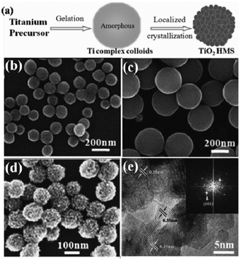 |
| | Fig. 1 (a) Schematic representation of the formation process of TiO2 HMSs; (b, c) SEM images of titanium diglycolate precursors prepared with different concentrations of water; SEM (d) and HRTEM (e) images of the mesoporous TiO2 spheres obtained after hydrothermal treatment of the precursor spheres. | |
To further increase the surface area and improve the crystallization of the TiO2 HMSs, we chose diethylene glycol as a coordinating reagent to prepare titanium diglycolate spheres, and then employed hydrothermal conversion of the precursors to produce well-crystallized TiO2 HMSs. The as-prepared products are uniform in diameter in the range 100–300 nm according to the differing H2O content (Fig. 1a–c). The BET specific surface area and pore volume of the sample are 193 m2 g−1 and 0.304 cm3 g−1, respectively. Interestingly, TEM images reveal that the HMSs are composed of nanocrystals of about 8 nm and keep a good interparticle connection caused by the partially oriented attachment of primary particles (Fig. 1e), which are expected to favor the effective charge transport through the film composed of mesoporous TiO2 spheres.7
In the above process, the crucial step is to control the hydrolysis rate to get the microsphere precursor. Among various methods, the sol–gel process is commonly used to generate the precursors.14,19–26 With low water content (H2O![[thin space (1/6-em)]](https://www.rsc.org/images/entities/char_2009.gif) :
:![[thin space (1/6-em)]](https://www.rsc.org/images/entities/char_2009.gif) Ti < 10), the hydrolysis of the Ti source could be easily controlled, in which the formation of spherical particles is proposed to follow the well-documented colloid coarsening and aggregation processes.18,19 On the other hand, with a higher water content, although processor spheres could also be generated following the LaMer model, in which the intermediate micelles aggregate and yield organic–inorganic hybrid clusters,23,27 it is hard to control the monodispersity of HMSs.
Ti < 10), the hydrolysis of the Ti source could be easily controlled, in which the formation of spherical particles is proposed to follow the well-documented colloid coarsening and aggregation processes.18,19 On the other hand, with a higher water content, although processor spheres could also be generated following the LaMer model, in which the intermediate micelles aggregate and yield organic–inorganic hybrid clusters,23,27 it is hard to control the monodispersity of HMSs.
In addition to obtaining uniform spherical precursors, intermediate products with different morphologies could also be obtained through a solvothermal method. Liao et al. fabricated hierarchical Ti-complex processor spheres consisting of nanoribbons by using titanium n-butoxide and acetic acid as raw materials.28 This synthetic concept could be further explored over a wider range. Bian et al. prepared a group of metal–organic composites with tunable structures, including solid spheres and hollow structures as well as flower-like particles, with mixtures of glycerol and various amounts of ethanol.29,30
2.2. Titanate precursor transformation
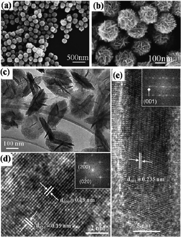
Besides the Ti-organic complexes, nanostructured titanates are also commonly used as titanium sources for the preparation of TiO2 with hierarchical microsphere structures. Zheng et al. synthesized primary precursor microspheres by the alcohothermal method. Then, under alkali hydrothermal treatment, these precursors transformed into titanate HMSs with a hierarchical nanotubular structure, which could finally transform into crystallized TiO2 HMSs.31 Li et al. developed a facile hydrothermal route for the large-scale preparation of urchin-like Na-titanate microspheres (Na-UTMSs) assembled by nanotubes with an ultrahigh surface area (Fig. 2a).32 The synthesis process involves the hydrothermal reaction of P25 in concentrated NaOH solution first and then hydrothermal transfer of the Na-TNT precursors into urchin-like Na-UTMSs by adding H2O2 under basic conditions. Na-UTMSs could be converted to H-UTMSs by proton exchange and then transferred to the anatase phase by annealing without destroying the morphology. Another method to convert the titanate to anatase is through the hydrothermal process. Li et al. found that HMSs composed of tetragonal faceted-nanorods (TFNRs) with a high percentage of high-energy {100} facets (Fig. 2b–e) could be achieved by hydrothermal treatment of urchin-liked Na-UTMSs under basic conditions. The urchin-like shape of the precursor is important for inducing the nucleation of TiO6 octahedra on its surface, and the gradual release of hydroxyl ions upon precursor decomposition would stabilize the active {100} facets. By changing the structure of the urchin-like Na-titanate precursor, the size of the TFNR components could be tuned.16
![(a) SEM image of the prepared urchin-liked Na-titanate (Na-UT) precursors; (b) and (c) low- and high-resolution SEM images of hierarchically structured anatase TiO2; (d) typical TEM image of an individual TFNR viewed along the [010] direction; (e) the corresponding SEAD patterns; (f) HRTEM image taken from (d) indicated by rectangles.](/image/article/2012/RA/c2ra22043a/c2ra22043a-f2.gif) |
| | Fig. 2 (a) SEM image of the prepared urchin-liked Na-titanate (Na-UT) precursors; (b) and (c) low- and high-resolution SEM images of hierarchically structured anatase TiO2; (d) typical TEM image of an individual TFNR viewed along the [010] direction; (e) the corresponding SEAD patterns; (f) HRTEM image taken from (d) indicated by rectangles. | |
Furthermore, the one-pot methods could be used to synthesize the hollow and core–shell structures. In fact, the microsphere precursors were also generated as intermediates, followed by the dissolution–recrystallization process.40 Compared with the hydrothermal method to obtain solid HMSs, the solvothermal method or the hydrothermal method with F− ions in the solvent could accelerate the dissolution process,41 thus leading to the generation of the hollow or core–shell structures. In this process, heterogeneous nucleation first occurred around the amorphous microspheres to form a thin crystalline shell. Then the amorphous particle interior dissolved and deposited on a porous crystalline external shell to produce intact hollow microspheres. In the latter step, a hollowing process was normally accompanied by a gradual decrease in the shell thickness40,42–45 or a sphere-in-shell intermediate.36 Which structure appears is correlated with the diffusion of the coordination agents.41 Moreover, the structure of the composition of the spheres could be tuned by the capping agents.36 Wu et al. prepared nanospindle-based hollow spheres using peroxotitanium complexes as a titanium source in the mixed solvent of H2O and ethanol.17 After the generation of amorphous spherical products, the dissolution–recrystallization process occurred with inner microspheres as a reservoir of Ti species under solvothermal conditions (Fig. 4a). In addition, NH4+ in the reaction system could hinder the growth of the lateral facets of the anatase structure, leading to selective growth of the spindle-like particles along the <001> direction (Fig. 4f,g).
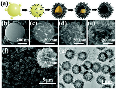 |
| | Fig. 4 (a) Scheme of the shape evolution from amorphous sphere to hierarchical hollow sphere; (b–e) SEM images of the intermediate products collected at different times. SEM (f) and TEM (g) images of the hierarchical hollow spheres. | |
2.5. Template method
Some organic microspheres, such as porous carbon or polymer spheres, have been used as sacrificial templates to construct the HMSs.48–58 After incorporation of the precursor, the templates were removed by calcination or solvent etching, leaving well-constructed HMSs.59,60 A “partial etching and re-calcination” strategy has been proposed to induce crystallization, while restricting the increase in the nanocrystal size of the HMSs.61,62 In some other systems, the dissolution process synchronously occurs during the deposition process of the products52,57
3. Structures and performances of TiO2 HMS-based DSSCs
3.1. Film structures
Because of its high surface area and large particle size, the TiO2 HMSs could be used as the ideal photoanode materials for DSSCs. In general, there are three types of photoanodes with the HMSs (Fig. 5). One type is the films only made of HMSs for light capturing (Fig. 5a). When the hierarchical spheres are used as the photoanodes in DSSCs (Fig. 6), the devices usually have a higher conversion efficiency than those made of P25, a commercial TiO2 product.14,20Table 1 shows the typical photovoltaic parameters of DSSCs made of either TiO2 HMSs or commercially-available P25 TiO2 nanoparticles. The conversion efficiency (η) of 8.20% has been achieved on the HMS based DSSCs with a thickness of ∼15 μm, which is more than 40% compared with P25 of an optimized thickness.20 Moreover, HMSs composed of {001} facet dominated nanosheets further increase the amount of dye adsorption, due to the high surface energy and strong ability to dissociatively anchor the COOH group, thus showing a great improvement in JSC and η.15 The TiO2 photoanodes made from the ATNHSs show a JSC of 17.9 mA cm−2 and a VOC of 0.65 V with an energy conversion efficiency (η) of 7.51%, whereas the photoanodes made from P25 nanoparticles give a JSC of 11.6 mA cm−2 and a VOC of 0.63 V with a η of 5.26%, indicating 54% and 43% increases in JSC and η compared to the P25 photoanodes of similar thickness, respectively (Fig. 7).
 |
| | Fig. 5 Scheme of three types of photoelectrode HMS based photoanode films: (a) solely composed of HMSs; (b) HMSs added on the top of the nanocrystallite film as a scattering layer; (c) mixtures of HMSs and nanocrystals. | |
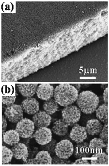 |
| | Fig. 6 SEM images of the films made of TiO2 HMSs with particle sizes ranging from 120 nm to 160 nm after calcination at 470 °C: (a) cross section view, (b) top view. | |
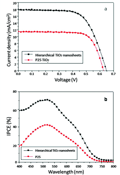 |
| | Fig. 7 (a) Comparison of the current–voltage characteristics of DSSCs based on the TiO2 nanosheet-based HMSs and P25 TiO2. (b) IPCE spectra as a function of wavelength in the dye-sensitized HMSs and P25 films with similar thickness (about 14 μm). | |
Table 1 Photovoltaic properties of the DSSCs made from TiO2 HMSs and commercially-available P25 TiO2 film with different thicknesses
| Sample |
Thickness (μm) |
J
SC (mA cm−2) |
V
OC (V) |
FF |
η
|
| HMSs |
∼12.5 |
14.08 |
0.744 |
0.70 |
7.37 |
| |
∼15.4 |
16.67 |
0.740 |
0.66 |
8.20 |
| P25 |
∼12.2 |
11.34 |
0.770 |
0.67 |
5.83 |
| |
∼15.2 |
8.85 |
0.740 |
0.73 |
4.81 |
Another type is the two-layered film with the HMSs on top of the nanocrystals as the scattering layer (Fig. 5b). For the cells with the HMSs on the top, except for the scattering effect, the upper layer could provide a high surface area for more dye loading, which could further improve the photocurrent as well as the conversion efficiency. Wu et al. have employed the hollow HMSs, which have the multi-reflection effect as the scattering layer, and obtained a JSC of 17.49 mA cm−2 and a conversion efficiency of 8.10%, which is ∼0.3% higher than when using large scattering particles.17
The third type of photoanode is the mixture of the HMSs with the nanocrystals, which can balance the light scattering effect and the dye adsorption loss due to the large voids in the film (Fig. 5c). TiO2 nanocrystals fill large voids or gaps between aggregates, resulting in the improvement of the amount of dye loading as well as the connectivity between the microspheres for charge transport. Xi et al. compared the conversion efficiencies of DSSCs made of the mixture of the HMSs and the nanocrystals with different ratios and found that the highest power conversion efficiency of 7.59% was achieved with the photoelectrode made from mixed 30 wt% TiO2 aggregates with 70 wt% nanocrystals.63
3.2. Light scattering effect
Theoretically, the nanosized particles usually cause weak Rayleigh scattering and could hardly scatter the incident light backwards. Large particles with comparative diameter were generally introduced as scattering centers to improve the harvest of the red and near infrared light. However, the large particles with diminished surface area inevitably reduce the dye loading amounts of the porous film and then jeopardize the conversion efficiency. Therefore, HMSs were adopted as dual-function materials to improve the scattering effect, while maintaining a reasonable dye loading capacity for the photoanode.64,65 Moreover, according to Mie theory, the scattering behavior of a system for an incident light wavelength λ could be expressed by the radius of the scattering particle r and the refractive index m. The complex Mie coefficients an and bn could be deduced by the Bessel–Riccatti functions Ψ and ξ and expressed as follows, where x = 2πr/λ.| |  |
(1)
|
| |  |
(2)
|
The scattering (Qsca), extinction (Qext) and absorption (Qabs) efficiencies could thus be expressed by
| |  |
(3)
|
,
| |  |
(4)
|
,
Considering the Mie coefficients have numerous poles in the complex plane, for a scattering system with fixed m a series of resonance peaks are expected to be observed. As displayed in Fig. 8a, we have calculated the scattering behavior of an anatase sphere with a reflection index of 2.5 in air. Moreover, based on the first three resonance peaks, it could be concluded that the scattering reinforcement occurs when λ = 0.6d, λ = 0.9d or λ = 1.9d, which roughly resembles periodic behavior, according to the diameter of the sphere. Several groups have previously investigated the size-dependent light-scattering effects.66,67 Typically, in our recent work, a number of scattering resonance peaks were observed for the photoanode film composed of different sized TiO2 hollow spheres, as displayed in Fig. 8b. Based on these findings, it is reasonable to anticipate that the diameter of the scattering particles could be intentionally designed for a photoanode to fulfill the scattering reinforcement at a particular wave range. In addition to the solid HMS, TiO2 HMS with hollow interiors or with double shell structures were also used to trapping incident light by means of multiple reflections.60,68
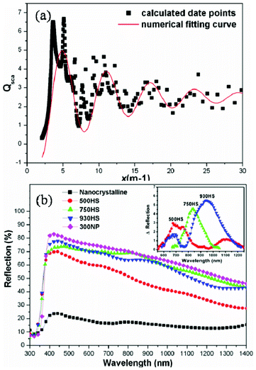 |
| | Fig. 8 (a) The scattering behavior as a function of x for an anatase sphere in air under a given refractive index m of 2.5. (b) The UV-Vis reflection spectra of the single layer films composed of 15–20 nm nanocrystalline, hollow spheres with different sizes and ∼300 nm commercial TiO2 particles. | |
3.3. Electron transport and recombination dynamics
Another structural merit of the HMS is that the highly crystallized and interconnected primary particles could lead to effective charge transport through the film, which is beneficial for the DSSC performance.22,69,70 Yang et al. found a significant electron recombination lifetime increase, revealing the effective retardation of the charge recombination reaction between the photoinjected electrons with I3− during electron transport through the film of HMSs. In order to further optimize the charge transport properties, HMSs with different functional blocks, such as nanosheets or nanorods, have been fabricated.15,28,71 Microspheres assembled by nanosheets were supposed to be a better choice because the thin sheets would also provide a large surface area, while favoring electron diffusion in the other two dimensions. Considering, one-dimensional (1D) structures could help to improve the collection efficiency due to the greatly decreased barrier effect; hierarchical TiO2 spheres consisting of anatase TiO2 nanorods were successfully used as trifunctional materials in DSSC applications. A high conversion efficiency was demonstrated, because of the higher charge-collection efficiency (faster electron transport and longer electron lifetime as shown in Fig. 9).28,71 Moreover, due to the interconnection effect of the HMSs, the TiO2 HMSs could be an excellent candidate in the flexible DSSCs, because a good connection among nanoparticles could not be achieved under the low temperatures necessary for the fabrication process of the flexible DSSCs.
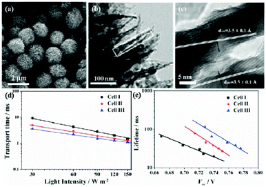 |
| | Fig. 9 SEM (a) and TEM (b,c) images of HMSs consisting of anatase nanorods and nanoparticles. Incident light intensity dependent transport time constant (d) and recombination time constant (e) as a function of open-circuit voltage for DSSCs based on films I (P25 nanoparticle), II (P25 nanoparticle + HMS) and III (HMS) (reproduced from ref. 28). | |
Although there are interconnections among small crystals or nanorods/nanosheets in the microspheres, the weak connection among the neighbouring microspheres sabotages the electron transport in the porous photoanodes. Kim et al. compared the diffusion coefficient of the DSSCs made of well-defined HMSs, deformed HMSs and nanoparticles, showing that the electron transport through partially deformed HMSs shows much faster electron transport than the uniform spheres.21 The mixture of TiO2 aggregates and nanocrystallites has the same features as the deformed spheres.63 Yan et al. modified the fabrication process of the film to agglutinate the microspheres together through a putative necking mechanism. The 3D necking greatly enhanced the inter-microsphere connectivity and facilitated electron transport, and finally an electron diffusion coefficient five times that of the control P25 film was obtained.25
3.4. Electrolyte diffusion
Upon decreasing the size of the TiO2 nanoparticles, the average pore size is decreased simultaneously, which is adverse for electrolyte diffusion. Hierarchical structures can provide two kinds of pores at the same time. Tiny internal pores were formed inside the TiO2 sphere, while large external pores were generated by the formation of interstitial voids among the spherical structures. The large external pores can be used as a “highway” for electrolyte diffusion, as shown in Fig. 10.21 Such inter-microsphere cavities are beneficial for the pore-filling process in quasi-solid state and fully solid state DSSCs. Microspheres with different sizes have been compared in the quasi-solid state DSSCs23 and the 400 nm-HMS based film showed the best electron transport properties resulting from the pore structure suited for the electrolyte penetration, either in or between the microspheres. In the ambipolar diffusion model, which was introduced to interpret the effect of cations on electron transport, fast Li+ diffusion is a key ingredient for assisting electron transport. The electrolyte diffusion also influences the electron recombination. Ionic liquids of 4-tert-butyl-pyridine and imidazole, which adsorb on the TiO2 surface and prolong the recombination time, would decrease in the film with small pores.
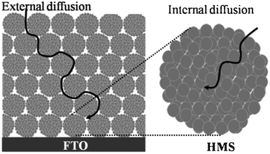 |
| | Fig. 10 Diagram for electrolyte diffusion through the external and internal pores in the film fabricated from the mesoporous TiO2 HMSs. | |
4. Conclusions and perspective
In conclusion, we have summarized recent progress in designing and fabricating TiO2 HMSs for high-performance DSSCs. The general synthetic strategies and the schemes for structural control were intensively reviewed in the first place. The previous research demonstrated that these materials could well balance the competition among the required structural qualities, such as large surface area, effective light scattering and electron transport capacities. Moreover, the review work focused on illustrating the correlation between the structural properties of the HMSs, such as surface area, porosity, primary building blocks and assembling patterns and their performances in DSSCs. The perspective will focus on the reasons preventing the HMS based DSSC from making striking improvements in power conversion efficiency. Moreover, the further optimization of the HMSs and their potential applications in other solar energy conversion devices are also discussed.
4.1 The limitation of the light absorption
For normally used N3 and N719 dyes, the extinction coefficient in the long-wavelength region is rather low for light absorption (Fig. 11a),72 which is one of the main restrictions of the improvement of DSSCs. Fig. 11b shows the calculated JSCvs. wavelength, in the assumption that all photons below the wavelength could be absorbed and converted into electrons.73 Considering the light loss from the reflection and absorption of the FTO glass, the JSC of a transparent film was calculated to be ∼15 mA cm−2, in the assumption that the incident light below 650 nm could be absorbed and the rest could not be employed due to the low extinction coefficient of the dyes. Setting the values of VOC and FF as 0.8 and 0.75, which are the relatively high experimental values, the calculated η is ∼9%. Introducing scattering particles could increase absorption in the range to a certain extent. By introducing the HMSs as the scattering layer, the experimental JSC has reached up to ∼19 mA cm−2 and the η could be ∼10.5% with N719 dye.28 However, further improvement is very hard to achieve because of the intrinsic drawbacks of the dye. N719 dye has an absorption onset of 800 nm and the maximum JSC could be calculated as 21.8 mA cm−2. Setting the same values of VOC and FF, the calculated η is 13.2%. Though the dyes with a greater molar extinction coefficient could be used, the potential room for a rise in JSC and η is very limited from the obtained value. If the absorption limit expands to 900 nm, the calculated JSC could increase to ∼30 mA cm−2 and the η could be 18%,74 which is more promising for further improvement of the DSSC. N749 (black dye) has a photocurrent onset of ∼900 nm; however, the obtained highest JSC was ∼21 mA cm−2, due to the low extinction coefficient in the long wavelength range.75 For the HMSs with rather large surface areas for dye adsorption and scattering effect, it is feasible to employ the dyes with strong absorption in the long wavelength to co-adsorb with the normal N719 on the semiconductor film to expand the range of the absorption wavelength and thus improve JSC.
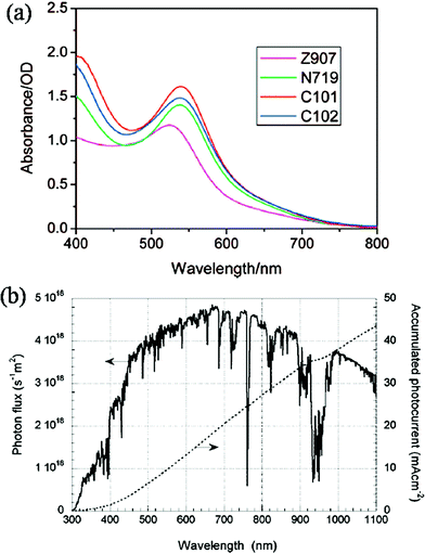 |
| | Fig. 11 (a) Absorption spectra of Z907, N719, C101 and C102 anchored on a 7 μm thick transparent nanocrystalline TiO2 film. (Reprinted with permission from ref. 72. Copyright (2008) American Chemical Society.) (b) Photo flux of the AM 1.5 G spectrum at 1000 W m−2 (ASTM G 173-03), and calculated accumulated photocurrent. (Reprinted with permission from ref. 73. Copyright (2010) American Chemical Society.) | |
4.2 Limitations of the HMS based photoanode
Although the HMSs were considered as a promising material to integrate multifunction for the photoanode of DSSCs, there are still some problems remaining unsolved. The first problem is the reflection loss. For the single-layer microsphere film, the high light scattering effect is accompanied with the reflection loss at the interface between the FTO and the TiO2 film, which decreases the light harvesting of the film. Therefore, most of the highly efficient DSSCs are employ the two-layer film. So it is important to optimize the size of the microspheres to balance the scattering effect and the reflection loss of the single-layer films. For the two-layer films, although the reflected light could be absorbed by the compact layer, the size of the microsphere should also be controlled for a good connection between the two layers, otherwise the electrons generated in the scattering layer will be lost in the interface of the two layers.
For the solid and quasi-solid DSSCs, the large voids are necessary for electrolyte diffusion; then the compact layer of crystals could be replaced with the small HMSs. A two-layer photoanode composed of different size HMSs should be designed to balance the electrolyte diffusion and light absorption in the film.
4.3 Further energy related applications of the HMS materials
Taking advantage of the genuine structural qualities, these HMS materials could also find further applications in other energy conversion devices. Compared with DSSCs, quantum-dot sensitized solar cells (QDSSCs) have a much higher theoretical conversion efficiency because of the unique hot electron transfer and carrier multiplication process.76 When utilized in QDSSCs, the large surface area of HMS could offer more arching sites for the narrow band gap Q-dots, and the interconnected TiO2 matrix could effectively transport the injected photoelectrons to the FTO substrate. Except for a few examples, the HMSs have been seldom used in QDSSCs.77 Moreover, the low coverage rate of Q-dots on the TiO2 surface results in more chances for electron recombination on the uncovered surface. Therefore, it is still imperative to come up with a new fabricating concept to achieve high and uniform coverage of the Q-dots, while maintaining a well-defined heterojunction interface. Owing to the above structural advantages: large surface area for exciton dissociation and continuous structure for improving electron transport, the HMSs could be also be applied in organic–semiconductor hybrid photovoltaics, which is based on the concept of the donor–acceptor bulk heterojunction, where the exciton could dissociate into electrons and holes and then transport in the separate materials.
In addition, TiO2 has been shown to be a potential anode material in lithium-ion batteries. In the nano/micro hierarchical structure, the nanosize encompasses a shorter length for both electronic and lithium ion transport, provides a greater electrode/electrolyte contact area and reduces the specific surface current rate. The microsize of the spherical morphology would facilitate TiO2 contact to form a compact electrode layer with higher compact packing density. It is expected that these hierarchical TiO2 microspheres would show superior applications as anode materials, especially for high volumetric energy or high power density lithium ion batteries.
Acknowledgements
This work is supported by NSFC (Grant Nos. 50821061 21133001 and 61176004) and MSTC (Grant Nos. 2007CB936201 and 2011CB808702). We also thank Xiaolan Zhong and Prof. Zhi-Yuan Li (Institute of Physics, Chinese Academy of Science, Bei Jing, P. R. Chian) for their assistance in the calculation works of Fig. 8a.
References
- B. Oregan and M. Gratzel, Nature, 1991, 353, 737–740 CrossRef CAS.
- M. Gratzel, Nature, 2001, 414, 338–344 CrossRef CAS.
- T. Yamaguchi, N. Tobe, D. Matsumoto and H. Arakawa, Chem. Commun., 2007, 4767–4769 RSC.
- M. Green, Progr. Photovolt.: Res. Appl., 2006, 14, 381–381 CrossRef.
- M. Adachi, Y. Murata, J. Takao, J. T. Jiu, M. Sakamoto and F. M. Wang, J. Am. Chem. Soc., 2004, 126, 14943–14949 CrossRef CAS.
- A. Usami, Chem. Phys. Lett., 1997, 277, 105–108 CrossRef CAS.
- J. Ferber and J. Luther, Sol. Energy Mater. Sol. Cells, 1998, 54, 265–275 CrossRef CAS.
-
(a) G. Rothenberger, P. Comte and M. Grätzel, Sol. Energy Mater. Sol. Cells, 1999, 58, 321–336 CrossRef CAS.
- Z.-S. Wang, H. Kawauchi, T. Kashima and H. Arakawa, Coord. Chem. Rev., 2004, 248, 1381–1389 CrossRef CAS.
- Y. Tachibana, K. Hara, K. Sayama and H. Arakawa, Chem. Mater., 2002, 14, 2527–2535 CrossRef CAS.
- Q. W. Chen and D. S. Xu, J. Phys. Chem. C, 2009, 113, 6310–6314 CAS.
- J.-Y. Liao, B.-X. Lei, H.-Y. Chen, D.-B. Kuang and C.-Y. Su, Energy Environ. Sci., 2012, 5, 5750–5757 CAS.
- Q. Zhang, T. P. Chou, B. Russo, S. A. Jenekhe and G. Cao, Angew. Chem., Int. Ed., 2008, 47, 2402–2406 CrossRef CAS.
- D. Chen, F. Huang, Y.-B. Cheng and R. A. Caruso, Adv. Mater., 2009, 21, 2206–2210 CrossRef CAS.
- W. Yang, J. Li, Y. Wang, F. Zhu, W. Shi, F. Wan and D. Xu, Chem. Commun., 2011, 47, 1809–1811 RSC.
- J. Li, K. Cao, Q. Li and D. Xu, CrystEngComm, 2012, 14, 83–85 RSC.
- D. Wu, F. Zhu, J. Li, H. Dong, Q. Li, K. Jiang and D. Xu, J. Mater. Chem., 2012, 22, 11665–11671 RSC.
- X. Jiang, T. Herricks and Y. Xia, Adv. Mater., 2003, 15, 1205–1209 CrossRef CAS.
- D. Chen, L. Cao, F. Huang, P. Imperia, Y.-B. Cheng and R. A. Caruso, J. Am. Chem. Soc., 2010, 132, 4438–4444 CrossRef CAS.
- W.-G. Yang, F.-R. Wan, Q.-W. Chen, J.-J. Li and D.-S. Xu, J. Mater. Chem., 2010, 20, 2870–2876 RSC.
- Y. J. Kim, M. H. Lee, H. J. Kim, G. Lim, Y. S. Choi, N.-G. Park, K. Kim and W. I. Lee, Adv. Mater., 2009, 21, 3668–3673 CrossRef CAS.
- H.-W. Chen, Y.-T. Liao, J.-G. Chen, K. C. W. Wu and K.-C. Ho, J. Mater. Chem., 2011, 21, 17511–17588 RSC.
- W. Chen, Y. Qiu, K. Yan and S. Yang, J. Power Sources, 2011, 196, 10806–10816 CrossRef CAS.
- J. H. Pan, Z. Cai, Y. Yu and X. S. Zhao, J. Mater. Chem., 2011, 21, 11430–11438 RSC.
- K. Yan, Y. Qiu, W. Chen, M. Zhang and S. Yang, Energy Environ. Sci., 2011, 4, 2168–2176 CAS.
- M. Ishida, S. W. Park, D. Hwang, Y. B. Koo, J. L. Sessler, D. Y. Kim and D. Kim, J. Phys. Chem. C, 2011, 115, 19343–19354 CAS.
- S. R. Gajjela, K. Ananthanarayanan, C. Yap, M. Gratzel and P. Balaya, Energy Environ. Sci., 2010, 3, 838–845 CAS.
- J.-Y. Liao, B.-X. Lei, D.-B. Kuang and C.-Y. Su, Energy Environ. Sci., 2011, 4, 4079–4085 CAS.
- Z. Bian, J. Zhu, J. Wang, S. Xiao, C. Nuckolls and H. Li, J. Am. Chem. Soc., 2012, 134, 2325–2331 CrossRef CAS.
- H. Li, Z. Bian, J. Zhu, D. Zhang, G. Li, Y. Huo, H. Li and Y. Lu, J. Am. Chem. Soc., 2007, 129, 8406–8407 CrossRef CAS.
- Z. Zheng, B. Huang, X. Qin, X. Zhang and Y. Dai, Chem.–Eur. J., 2010, 16, 11266–11270 CrossRef CAS.
- J. Li, W. Wan, F. Zhu, Q. Li, H. Zhou, J. Li and D. Xu, Chem. Commun., 2012, 48, 389–391 RSC.
- L. Xiang, X. Zhao, J. Yin and B. Fan, J. Mater. Sci., 2012, 47, 1436–1445 CrossRef CAS.
- D. Truong, M. Kobayashi, H. Kato and M. Kakihana, J. Ceram. Soc. Jpn., 2011, 119, 513–516 CrossRef.
- Z. Zheng, B. Huang, X. Qin, X. Zhang, Y. Dai, M. Jiang, P. Wang and M.-H. Whangbo, Chem.–Eur. J., 2009, 15, 12576–12579 CrossRef CAS.
- S. Liu, J. Yu and M. Jaroniec, J. Am. Chem. Soc., 2010, 132, 11914–11916 CrossRef CAS.
- W. Q. Fang, J. Z. Zhou, J. Liu, Z. G. Chen, C. Yang, C. H. Sun, G. R. Qian, J. Zou, S. Z. Qiao and H. G. Yang, Chem.–Eur. J., 2011, 17, 1423–1427 CrossRef CAS.
- Z. Zheng, B. Huang, J. Lu, X. Qin, X. Zhang and Y. Dai, Chem.–Eur. J., 2011, 17, 15032–15038 CrossRef CAS.
- J. S. Chen, Y. L. Tan, C. M. Li, Y. L. Cheah, D. Luan, S. Madhavi, F. Y. C. Boey, L. A. Archer and X. W. Lou, J. Am. Chem. Soc., 2010, 132, 6124–6130 CrossRef CAS.
- S. W. Liu, J. G. Yu and S. Mann, Nanotechnology, 2009, 20, 325606–325613 CrossRef.
- J. Yu and J. Zhang, Dalton Trans., 2010, 39, 5860–5867 RSC.
- J. G. Yu, H. Guo, S. A. Davis and S. Mann, Adv. Funct. Mater., 2006, 16, 2035–2041 CrossRef CAS.
- J. Yu, S. Liu and H. Yu, J. Catal., 2007, 249, 59–66 CrossRef CAS.
- J. Yu, J. Fan and L. Zhao, Electrochim. Acta, 2010, 55, 597–602 CrossRef CAS.
- J. Yu, Q. Xiang, J. Ran and S. Mann, CrystEngComm, 2010, 12, 872–879 RSC.
- F. Bai, D. Wang, Z. Huo, W. Chen, L. Liu, X. Liang, C. Chen, X. Wang, Q. Peng and Y. Li, Angew. Chem., 2007, 119, 6770–6773 CrossRef.
- J. T. Park, D. K. Roh, R. Patel, E. Kim, D. Y. Ryu and J. H. Kim, J. Mater. Chem., 2010, 20, 8521–8530 RSC.
- J. Chen, Z. Hua, Y. Yan, A. A. Zakhidov, R. H. Baughman and L. Xu, Chem. Commun., 2010, 46, 1872–1874 RSC.
- A. Dong, N. Ren, Y. Tang, Y. Wang, Y. Zhang, W. Hua and Z. Gao, J. Am. Chem. Soc., 2003, 125, 4976–4977 CrossRef CAS.
- S. C. Yang, D. J. Yang, J. Kim, J. M. Hong, H. G. Kim, I. D. Kim and H. Lee, Adv. Mater., 2008, 20, 1059–1064 CrossRef CAS.
- J. H. Park, S. Y. Jung, R. Kim, N.-G. Park, J. Kim and S.-S. Lee, J. Power Sources, 2009, 194, 574–579 CrossRef CAS.
- J. Liu, L. Chang, J. Wang, M. Zhu and W. Zhang, Mater. Sci. Eng., B, 2010, 172, 142–145 CrossRef CAS.
- L. Wang, T. Sasaki, Y. Ebina, K. Kurashima and M. Watanabe, Chem. Mater., 2002, 14, 4827–4832 CrossRef CAS.
- Y. Kondo, H. Yoshikawa, K. Awaga, M. Murayama, T. Mori, K. Sunada, S. Bandow and S. Iijima, Langmuir, 2007, 24, 547–550 CrossRef.
- H. Wang, Z. Wu and Y. Liu, J. Phys. Chem. C, 2009, 113, 13317–13324 CAS.
- X. Sun, J. Liu and Y. Li, Chem.–Eur. J., 2006, 12, 2039–2047 CrossRef CAS.
- S. Ding, F. Huang, X. Mou, J. Wu and X. Lu, J. Mater. Chem., 2011, 21, 4888–4892 RSC.
- F. Zhang, Y. Zhang, S. Song and H. Zhang, J. Power Sources, 2011, 196, 8618–8624 CrossRef CAS.
- Y. Zeng, X. Wang, H. Wang, Y. Dong, Y. Ma and J. Yao, Chem. Commun., 2010, 46, 4312–4314 RSC.
- X. Wu, G. Q. Lu and L. Wang, Energy Environ. Sci., 2011, 4, 3565–3572 CAS.
- J. B. Joo, Q. Zhang, I. Lee, M. Dahl, F. Zaera and Y. Yin, Adv. Funct. Mater., 2012, 22, 166–174 CrossRef CAS.
- J. B. Joo, Q. Zhang, M. Dahl, I. Lee, J. Goebl, F. Zaera and Y. Yin, Energy Environ. Sci., 2012, 6321–6327 CAS.
- J. Xi, Q. Zhang, K. Park, Y. Sun and G. Cao, Electrochim. Acta, 2011, 56, 1960–1966 CrossRef CAS.
- W. E. Vargas and G. A. Niklasson, Sol. Energy Mater. Sol. Cells, 2001, 69, 147–163 CrossRef CAS.
- U. Akira, Sol. Energy Mater. Sol. Cells, 1999, 59, 163–166 CrossRef.
- I. G. Yu, Y. J. Kim, H. J. Kim, C. Lee and W. I. Lee, J. Mater. Chem., 2011, 21, 532–538 RSC.
- Y.-C. Park, Y.-J. Chang, B.-G. Kum, E.-H. Kong, J. Y. Son, Y. S. Kwon, T. Park and H. M. Jang, J. Mater. Chem., 2011, 21, 9582–9586 RSC.
- J. Qian, P. Liu, Y. Xiao, Y. Jiang, Y. Cao, X. Ai and H. Yang, Adv. Mater., 2009, 21, 3663–3667 CrossRef CAS.
- S. H. Jang, Y. J. Kim, H. J. Kim and W. In Lee, Electrochem. Commun., 2010, 12, 1283–1286 CrossRef CAS.
- F. d. r. Sauvage, D. Chen, P. Comte, F. Huang, L.-P. Heiniger, Y.-B. Cheng, R. A. Caruso and M. Graetzel, ACS Nano, 2010, 4, 4420–4425 CrossRef CAS.
- F. Hao, H. Lin, C. Zhou, Y. Liu and J. Li, Phys. Chem. Chem. Phys., 2011, 13, 15918–15924 RSC.
- F. Gao, Y. Wang, D. Shi, J. Zhang, M. Wang, X. Jing, R. Humphry-Baker, P. Wang, S. M. Zakeeruddin and M. Grätzel, J. Am. Chem. Soc., 2008, 130, 10720–10728 CrossRef CAS.
- A. Hagfeldt, G. Boschloo, L. Sun, L. Kloo and H. Pettersson, Chem. Rev., 2010, 110, 6595–6663 CrossRef CAS.
- M. Grätzel, Acc. Chem. Res., 2009, 42, 1788–1798 CrossRef.
- P. Péchy, T. Renouard, S. M. Zakeeruddin, R. Humphry-Baker, P. Comte, P. Liska, L. Cevey, E. Costa, V. Shklover, L. Spiccia, G. B. Deacon, C. A. Bignozzi and M. Grätzel, J. Am. Chem. Soc., 2001, 123, 1613–1624 CrossRef.
- P. V. Kamat, K. Tvrdy, D. R. Baker and J. G. Radich, Chem. Rev., 2010, 110, 6664–6688 CrossRef CAS.
- X. Y. Yu, J. Y. Liao, K. Q. Qiu, D. B. Kuang and C. Y. Su, ACS Nano, 2011, 5, 9494–9500 CrossRef CAS.
|
| This journal is © The Royal Society of Chemistry 2012 |
Click here to see how this site uses Cookies. View our privacy policy here. 
![[thin space (1/6-em)]](https://www.rsc.org/images/entities/char_2009.gif) :
:![[thin space (1/6-em)]](https://www.rsc.org/images/entities/char_2009.gif) Ti < 10), the hydrolysis of the Ti source could be easily controlled, in which the formation of spherical particles is proposed to follow the well-documented colloid coarsening and aggregation processes.18,19 On the other hand, with a higher water content, although processor spheres could also be generated following the LaMer model, in which the intermediate micelles aggregate and yield organic–inorganic hybrid clusters,23,27 it is hard to control the monodispersity of HMSs.
Ti < 10), the hydrolysis of the Ti source could be easily controlled, in which the formation of spherical particles is proposed to follow the well-documented colloid coarsening and aggregation processes.18,19 On the other hand, with a higher water content, although processor spheres could also be generated following the LaMer model, in which the intermediate micelles aggregate and yield organic–inorganic hybrid clusters,23,27 it is hard to control the monodispersity of HMSs.![(a) SEM image of the prepared urchin-liked Na-titanate (Na-UT) precursors; (b) and (c) low- and high-resolution SEM images of hierarchically structured anatase TiO2; (d) typical TEM image of an individual TFNR viewed along the [010] direction; (e) the corresponding SEAD patterns; (f) HRTEM image taken from (d) indicated by rectangles.](/image/article/2012/RA/c2ra22043a/c2ra22043a-f2.gif)


