Study of melilite based glasses and glass-ceramics nucleated by Bi2O3 for functional applications
Allu Amarnath
Reddy
a,
Dilshat U.
Tulyaganov
ab,
Saurabh
Kapoor
a,
Ashutosh
Goel
c,
Maria J.
Pascual
d,
Vladislav V.
Kharton
a and
José M. F.
Ferreira
*a
aDepartment of Materials and Ceramic Engineering, University of Aveiro, CICECO, 3810–193 Aveiro, Portugal. E-mail: jmf@ua.pt; Tel: +351-234-370242; Fax: +351-234-370204
bTurin Polytechnic University in Tashkent, 17, Niyazova str., 100095, Tashkent, Uzbekistan
cSterlite Technologies Ltd, E1, E2, E3, MIDC Waluj, Aurangabad, 431136, India
dInstituto de Cerámica y Vidrio (CSIC), C/Kelsen 5, Campus de Cantoblanco, 28049 Madrid, Spain
First published on 17th September 2012
Abstract
Bi2O3-nucleated melilite based glasses and glass-ceramics (GCs) in the system CaO–MgO–Al2O3–SiO2–La2O3 have been appraised for solid electrolyte sealing applications in high-temperature electrochemical devices, such as solid oxide fuel cells and oxygen pumps . The structure of the glasses was assessed by Fourier transform infrared (FTIR) and 29Si and 27Al magic angle spinning nuclear magnetic resonance (MAS-NMR) spectroscopy. The crystallization kinetics and sintering behaviour were investigated by differential thermal analysis and hot stage microscopy. All glass compositions exhibited single-stage shrinkage behaviour. X-ray diffraction (XRD), in conjunction with the Rietveld-RIR (reference intensity ratio) technique, was employed to quantify the crystalline and amorphous phases in GCs sintered under non-isothermal conditions for 1 h within the operating temperature range (850–900 °C). Merwinite and melilite (the solid solutions of akermanite and gehlenite) were revealed as the major crystalline phases formed in GCs. The amount of GC in the melilite phase increased significantly from 850 to 900 °C at the expense of merwinite. The coefficients of thermal expansion (CTE (200–700 °C)), 10.2–10.9 × 10⁻⁶ K−1 for the glasses and 9.8–11.2 × 10⁻⁶ K−1 for the GCs, are in good agreement with those typical for solid oxide electrolytes, such as 8 mol% yttria-stabilized zirconia (8YSZ), and metallic interconnects, such as Sanergy HT. Long term thermal stability studies demonstrate stable behaviour for the crystalline phase assemblage and chemical composition, CTE (200–700 °C) values of 9.9–11.7 × 10⁻⁶ K−1, and good adjoining performance with the metal and electrolyte. The well matched CTE values and good adhesion to the other components in both air and a reducing atmosphere allow us to propose further research into the parent compositions as stabilized zirconia sealants. Glasses demonstrating bulk nucleation may also attract interest for other functional applications in optical and electronic devices.
1 Introduction
Due to their numerous economic, technological and environmental advantages, interest in fuel cells and other solid-electrolyte devices, such as high-temperature electrolyzers of steam and carbon dioxide, oxygen pumps and sensors, has increased significantly in recent years. In particular, the solid oxide fuel cell (SOFC) is one of the most promising designs because of the high stability of the oxide materials.1 However, the most arduous task in the commercialization of planar designs of SOFCs, electrolyzers and other devices is providing a hermetic seal between their ceramic and metallic components, such that the resulting joints remain rugged and stable over the lifetime of the stack. The seals must have CTE values similar to those of the other cell components (10–12 × 10−6 K−1), be stable in a wide range of oxygen partial pressures (air and fuel) and be chemically compatible with other components, while also minimizing thermal stresses during high–temperature operation. These demands constitute a major challenge in the development of planar SOFCs.2,3 The same problem has critical importance for solid-electrolyte oxygen pumps and compressors operating under oxidizing conditions and for electrolyzers, where the oxygen chemical potentials may be even lower than in SOFCs.Most recently, there has been a dramatic revival of interest in both glass- and GC-to-metal seals, particularly for new applications including sealants. Substantial work is in progress in this area, aiming at improving the performance of these sealants under extreme operating conditions, which involve both high temperatures and, often, highly corrosive environments. Most of the GC based sealants proposed so far are alkali/alkaline–earth aluminosilicate, borate or borosilicate GCs.4–6 However, designing glass-based seals meeting high CTE requirements along with prolonged thermal and chemical stability is a difficult task. For example, a barium calcium aluminosilicate based glass seal, designed by scientists from Pacific Northwest National Laboratory, USA and commonly known as G18 glass,7 is prone to crystallization of low thermal expansion phase monoclinic celsian (BaAl2Si2O8) during long term SOFC operation and exhibits severe interfacial reactions with metallic SOFC components,8 thus raising serious concerns about its suitability in a SOFC stack. Similar concerns with respect to the formation of monoclinic celsian have been reported for seals designed in other aluminosilicate glass system.9 On the other hand, the glass seals proposed by Smeacetto et al.10 contain significant amounts of Na2O, which might affect the sealant stability11 and also promote degradation of other components due to volatilization and fast diffusion at elevated temperatures.
In general, the following specifications should be considered when designing glass compositions for SOFC seals: (i) glass compositions should be in the primary phase fields of crystalline phases with high CTE; (ii) the as-designed glasses should show good sintering ability and high mechanical strength, in order to provide hermeticity to the seal; (iii) the compositions should not be highly refractory in nature and should exhibit good flow behaviour at SOFC operation temperature; (iv) the crystalline phases anticipated to form in the as-designed glass seal should not exhibit polymorphic transformations during thermal treatments, as these affect their thermal stability; (v) the glass components should exhibit minimal reactivity with ceramic/metallic SOFC components, and (vi) the glasses should not be highly prone to crystallization, as the presence of residual glassy phase allows the healing of micro-cracks which develop in the seal during thermal cycling. In the case of solid-electrolyte oxygen pumps, compressors and electrolyzers, the requirements are very similar, except for differences associated with cell designs and operating conditions, primarily oxygen partial pressure range.
Melilites, a group of tetragonal minerals found in igneous and metamorphic rocks, are considered to be among the first silicate minerals to have crystallized from the solar nebula. They belong to the family of sorosilicates with general formula (Ca2(Al,Mg)[(Al,Si)SiO7]). Most melilite minerals are solid solutions of akermanite [Ca2(MgSi2O7)] and gehlenite [Ca2(Al2SiO7)]. Melilite based glasses and glass-ceramics have not been studied so far as potential sealant materials. Orisini et al.,12 and more recently Gillot et al.,13 studied the crystallization behaviour of melilites and found a first crystallization of Ca-rich phase merwinite at ∼850 °C (the operating temperature of most SOFCs), which was attributed to the high mobility of Ca ion, followed by the congruent crystallizations of melilite phases at higher temperatures. Moore and Takaharu14 reported that the denser packed structure of merwinite, in comparison to melilites, may result in sintered GCs with lower CTE values. The low melting point and volatilization of Bi2O3 are expected to improve sintering and the formation of gas-tight seals, as large fractions of bismuth oxide additive may be evaporated during first thermal cycles. This could enable good thermal and chemical stability in merwinite-free isochemically crystallized melilite GCs, with minimum concentration of Bi2O3 dissolved in the crystalline phase assemblage. Note that these features make it possible to use small additions of Bi2O3 in the SOFC materials,15–21 despite potential corrosion processes which may be induced by reduction of remaining bismuth cations. Furthermore, the formation of metallic Bi and related corrosive species cannot be expected under the operating conditions of oxygen pumps and compressors, where the oxygen partial pressures are substantially higher compared to SOFCs.22 For example, long term thermal stability of the crystalline phases and CTE values of GCs was achieved in diopside based glass-ceramics with added Bi2O3.4
The present work aimed to synthesise melilite type GCs and investigate their suitability as potential sealant materials for stabilized zirconia and metallic interconnects. Specifically, we investigated the effect of adding varying amounts (1–5 wt%) of Bi2O3 on the structure, the sintering and crystallization behaviours of glasses, the thermal properties of GCs, etc. Bi2O3 can tailor the seal properties by influencing glass devitrification, playing the role of a nucleating agent.9 La2O3 was also added to all glass compositions to improve their thermal stability during long term heat treatments. Being Ba-free, these glasses/GCs constitute a good alternative to the most widely studied Ba-containing GCs for sealing applications.
2 Experimental procedure
2.1 Synthesis of glasses
Four glasses with nominal compositions (wt%) corresponding to (95–x)Ca2Mg0.5Al1.0 Si 1.5 O7 + xBi2O3 + 5 La2O3, where x = 0, 1, 3 or 5, were synthesized by melt–quenching technique. Table 1 presents the detailed compositions of the glasses. The glasses have been labelled in accordance with their respective Bi2O3 contents (wt%), i.e., MB–0, MB–1, MB–3 and MB–5. High purity powders of SiO2 (>99.5%), Al2O3 (Sigma Aldrich, >98%), CaCO3 and MgCO3 (BDH chemicals, UK, >99%), La2O3 (Sigma Aldrich, 99.9%) and Bi2O3 (Sigma Aldrich, 99.9%) were used. Homogeneous batch mixtures of ∼100 g (Table 1), obtained by ball milling, were preheated at 900 °C for 1 h for decarbonization and then melted in Pt crucibles at 1590 °C for 1 h in air. Glasses in bulk form were produced by pouring the melts into preheated cylindrical bronze moulds, followed by annealing at temperatures around the glass transition temperature (Tg), before glass frits were obtained by quenching the glass melts in cold water. The frits were dried and then milled in a high-speed agate mill, resulting in fine glass powders with mean particle sizes of 10–15 μm (determined by light scattering technique; Coulter LS 230, Beckman Coulter, Fullerton CA; Fraunhofer optical model). The amorphous nature of the glasses was confirmed by XRD analysis (Rigaku Geigerflex D/Max, Tokyo, Japan; C Series; Cu-Kα radiation; 2θ range 10°–80°; step 0.02° s−1).| Glass | CaO | MgO | SiO2 | Al2O3 | La2O3 | Bi2O3 |
|---|---|---|---|---|---|---|
| MB–0 | ||||||
| wt% | 38.97 | 7.01 | 31.31 | 17.71 | 5.00 | 0.00 |
| mol% | 44.01 | 11.02 | 33.00 | 11.00 | 0.97 | 0.00 |
| MB–1 | ||||||
| wt% | 38.56 | 6.93 | 30.98 | 17.53 | 5.00 | 1.00 |
| mol% | 43.95 | 10.99 | 32.96 | 10.99 | 0.98 | 0.14 |
| MB–3 | ||||||
| wt% | 37.74 | 6.78 | 30.32 | 17.16 | 5.00 | 3.00 |
| mol% | 43.82 | 10.95 | 32.85 | 10.96 | 1.00 | 0.42 |
| MB–5 | ||||||
| wt% | 36.92 | 6.63 | 29.67 | 16.78 | 5.00 | 5.00 |
| mol% | 43.68 | 10.91 | 32.76 | 10.92 | 1.02 | 0.71 |
2.2 Density and dilatometric behaviour
Archimedes' method (immersion in diethyl phthalate) was employed to measure the apparent density of the bulk annealed glasses. The obtained density values were further employed, along with the composition of the glasses, to calculate their molar volume and excess volume. CTE of glasses and GCs were obtained from dilatometry measurements carried out on prismatic samples with a cross section of 4 mm × 5 mm (Bahr Thermo Analyze DIL801 L, Hullhorst, Germany; heating rate 5 K min−1).2.3 Structural characterization of glasses
Infrared spectra for the glass powders were obtained using an infrared Fourier spectrometer (FT–IR, model Mattson Galaxy S7000, USA). For this, each powder sample was mixed with KBr in the proportion of 1/150 (by weight) and pressed into a pellet using a hand press. 64 scans for background and 64 scans per sample were made with signal gain 1. The resolution was 4 cm−1.29Si MAS-NMR spectra were recorded on a Bruker ASX 400 spectrometer operating at 79.52 MHz (9.4 T), using a 7 mm probe at a spinning rate of 5 kHz. The pulse length was 2 μs and 60 s delay time was used. Kaolinite was used as the chemical shift reference. 27Al MAS-NMR spectra were recorded on a Bruker ASX 400 spectrometer operating at 104.28 MHz (9.4 T), using a 4 mm probe at a spinning rate of 15 kHz. The pulse length was 0.6 μs and 4 s delay time was used. Al(NO3)3 was used as the chemical shift reference.
2.4 Thermal analysis of glasses and crystallization kinetics
The sintering behaviour of the glass powders was investigated using a side-view hot stage microscope (HSM) EM 201 equipped with image analysis system and 1750/15 Leica electrical furnace. The cylindrical shaped samples with height and diameter of ≈3 mm were prepared by cold-pressing the glass powders. The cylindrical samples were placed on a 10 × 15 × 1 mm alumina (>99.5 wt% Al2O3) support. The temperature was measured with a Pt![[thin space (1/6-em)]](https://www.rsc.org/images/entities/char_2009.gif) :Rh (6:30) thermocouple contacted under the alumina support. The microscope projects the image of the sample through a quartz window and onto the recording device. The computerized image analysis system automatically records and analyses the geometry changes of the sample during heating. The image analyser measures the height of the sample during firing, taking into account the thermal expansion of the alumina substrate, with the base as a reference. The HSM software calculates the percentage decrease in height, width and area of the sample images. The measurements were conducted in air with a heating rate of 5 K min−1. The temperatures corresponding to the characteristic viscosity points (first shrinkage, maximum shrinkage) were obtained from the photographs taken during the HSM experiment following Scholze's definition.23,24 Crystallization kinetics of the glasses was studied using differential thermal analysis (DTA–TG, Setaram Labsys, Setaram Instrumentation, Caluire, France). 50 mg of glass powder was contained in an alumina crucible and the reference material was α–alumina powder. Several DTA scans were recorded from room temperature to 1000 °C at heating rates (β) of 5, 10, 20 and 30 K min−1. The values of Tg, crystallization onset temperature (Tc) and peak temperature of crystallization (Tp) were obtained from the DTA thermographs.
:Rh (6:30) thermocouple contacted under the alumina support. The microscope projects the image of the sample through a quartz window and onto the recording device. The computerized image analysis system automatically records and analyses the geometry changes of the sample during heating. The image analyser measures the height of the sample during firing, taking into account the thermal expansion of the alumina substrate, with the base as a reference. The HSM software calculates the percentage decrease in height, width and area of the sample images. The measurements were conducted in air with a heating rate of 5 K min−1. The temperatures corresponding to the characteristic viscosity points (first shrinkage, maximum shrinkage) were obtained from the photographs taken during the HSM experiment following Scholze's definition.23,24 Crystallization kinetics of the glasses was studied using differential thermal analysis (DTA–TG, Setaram Labsys, Setaram Instrumentation, Caluire, France). 50 mg of glass powder was contained in an alumina crucible and the reference material was α–alumina powder. Several DTA scans were recorded from room temperature to 1000 °C at heating rates (β) of 5, 10, 20 and 30 K min−1. The values of Tg, crystallization onset temperature (Tc) and peak temperature of crystallization (Tp) were obtained from the DTA thermographs.
2.5 Crystalline phase evolution in GCs
Cylindrical pellets with 20 mm diameter and ∼3 mm thickness were prepared from glass powders by uniaxial pressing (80 MPa). The powder compacts were sintered under non-isothermal conditions for 1 h at 850 and 900 °C and under isothermal conditions for 300 h at 900 °C. A slow heating rate of 5 K min−1 was maintained in order to prevent deformation of the samples. In order to study the thermal stability and applicability of these glasses and GCs for real applications, glass powder compacts which had already been sintered at 900 °C for 1 h under air atmosphere were further exposed to flowing humidified 10% H2:90% N2 gas mixture at 850 °C for 100 h.
The chemical compositions of some of the as-synthesized glasses and GCs produced under humidified 10% H2:90% N2 gas mixture at 850 °C for 100 h were analyzed by inductive coupled plasma-optical emission spectroscopy (ICP-OES; Jobin Yvon, JY 70 plus, France) in order to observe the differences between the designed and as-synthesized glass compositions.
The linear shrinkage during sintering was calculated from the difference of the diameter between the green and the sintered pellets. Archimedes' method (immersion in diethyl phthalate) was also employed to measure the apparent density of the glass-ceramics. The mean values and the standard deviation presented for linear shrinkage and density have been obtained from five different samples.
The amorphous nature of the glasses and qualitative, along with quantitative, analyses of crystalline phases in the GCs (crushed to particle size <45 mm) were measured by XRD analysis using a conventional Bragg–Brentano diffractometer (Philips PW 3710, Eindhoven, The Netherlands) with Ni-filtered Cu–K radiation. The quantitative phase analysis of GCs was made by a combined Rietveld-RIR method. 10 wt% corundum (NIST SRM 676a) was added to all the GC samples as an internal standard. The mixtures, which were ground in an agate mortar, were side loaded in an aluminium flat holder in order to minimize problems with the preferred orientation. Data were recorded using 2θ angle range of 15°–115°, step of 0.02° s−1. The phase fractions extracted by Rietveld-RIR refinements, using GSAS (General Structure Analysis System) software and EXPGUI as a graphical interface, were rescaled on the basis of the absolute weight of corundum originally added to their mixtures as an internal standard and, therefore, internally renormalized. The background was successfully fitted with a Chebyshev function with a variable number of coefficients depending on its complexity. The peak profiles were modelled using a pseudo-Voigt function with one Gaussian and one Lorentzian coefficient. Lattice constants, phase fractions, and coefficients corresponding to sample displacement and asymmetry were also refined.
2.6 Joining behaviour and chemical interactions between electrolyte/seal and interconnect/seal diffusion couples
To investigate the adhesion and chemical interactions of the glasses with SOFC components, wetting experiments between glasses (powder)–solid electrolyte (8YSZ) and glass–interconnect (Sanergy HT) were carried out. The glass powders (40% solid content mixed with 5 vol% solution of polyvinyl alcohol (PVA), prepared by dissolution of PVA in warm water) were deposited on 8YSZ electrolyte and on Sanergy HT by slurry coating. The diffusion couples were heated to 900 °C with a relatively slow β of 2 K min−1 and kept at that temperature for 1 h and 300 h. Heat treatment was further performed in a tubular furnace for 100 h at 850 °C without applying any dead load.2.7 SEM–EDS analysis
Microstructural observations were made on polished surfaces of the sintered glass powder compacts (chemically etched by immersion in 2 vol% HF solution for a duration of 2 min) by scanning electron microscopy (SEM; SU–70, Hitachi) with energy dispersive spectroscopy (EDS; Bruker Quantax, Germany) to study the distribution of elements in the crystals and along the GCs–interconnect diffusion couples.3 Results
3.1 Glass forming ability and glass properties
All the four glass compositions were suitable for easy casting after 1 h of melting at 1590 °C, resulting in homogeneous and transparent glasses. Table 2 presents the experimental compositions for MB–1 and MB–5 glasses by ICP-OES analysis. Negligible changes were observed in the chemical composition of the glasses after melting the glass batch, except for moderate losses of Bi2O3, as was expected. The amorphous nature of the quenched glasses and frits was confirmed by XRD analysis. The mean particle size of the glass powders used in the present investigation is between 10–15 μm.The density of the glasses (Table 3) increased with addition of Bi2O3, due to its high density in comparison with other constituents of the glasses. A similar trend in molar volume (MV) was also observed with increasing Bi2O3 in the glasses. The MV of the glasses increases due to an increase in bond length or inter atomic spacing. In the present scenario, such an increase is due to the greater ionic radius of Bi (0.102 nm for Bi3+ and 0.076 for Bi5+) in comparison to the ionic radii of other glass constitutes (Si4+ = 0.026 nm; Al3+ = 0.039 nm; Mg2+ = 0.058 nm; Ca2+ = 0.100 nm). Therefore, the volume corresponding to the structural unit with its surrounding space, Vm, is expected to increase by inserting a heavy metal oxide like Bi2O3. The density and MV data are in good agreement with the results reported by Ahlawat et al.25
| Properties of glass | MB–0 | MB–1 | MB–3 | MB–5 |
|---|---|---|---|---|
| a CTE values were obtained from dilatometry. | ||||
| Density (g cm−3) | 3.02 ± 0.001 | 3.03 ± 0.001 | 3.07 ± 0.005 | 3.11 ± 0.004 |
| MV (cm3 mol−1) | 20.96 ± 0.01 | 21.06 ± 0.02 | 21.20 ± 0.004 | 21.31 ± 0.05 |
| Excess MV (cm3 mol−1) | 1.57 ± 0.01 | 1.62 ± 0.04 | 1.66 ± 0.04 | 1.65 ± 0.05 |
| CTE (× 10−6 K−1) | 10.9 | 10.2 | 10.6 | 10.9 |
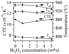
CTE (200–700 °C) of the glasses obtained from the expansion curves (not shown) are listed in Table 3. It can be seen that the CTE of the glasses varied between 10.2–10.9 × 10⁻⁶ K−1. The CTE value of MB–0 glass (10.9 × 10⁻⁶ K−1) decreased to 10.2 × 10⁻⁶ K−1 after the first addition of Bi2O3 and then gradually increased up to 10.9 × 10⁻⁶ K−1 with further additions.
The DTA thermographs of all the glass powders exhibit the characteristic endothermic effects attributed to structural modifications (Fig. 1). The Tg values reported in Table 4 correspond to the mid-point of the endothermic dip in the DTA thermographs26 of glass powders under a heating rate of 10 K min−1, since Tg could not be accurately detected at 5 K min−1. The variations in thermal parameters reported in Fig. 2 show a linear decreasing trend for Tg with increasing Bi2O3 content within the concentration range used.
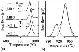 | ||
| Fig. 1 (a) DTA thermographs of investigated glasses at 10 K min−1 heating rates (b) Deconvolution of exothermic peak. | ||
 | ||
| Fig. 2 Variation in thermal parameters with increasing Bi2O3 content in the investigated glasses. | ||
| MB–0 | MB–1 | MB–3 | MB–5 | |
|---|---|---|---|---|
| T g ± 2 (°C) | 799 | 796 | 794 | 789 |
| T FS ± 5 (°C) | 820 | 800 | 814 | 820 |
| T MS ± 5 (°C) | 882 | 870 | 885 | 877 |
| T c ± 2 (°C) | 877 | 876 | 868 | 867 |
| T p1 ± 2 (°C) | 905 | 904 | 893 | 888 |
| T p2 ± 2 (°C) | 935 | 935 | 925 | 912 |
| A/A0 (ratio of final area to initial area of the glass powder) at TMS | 0.67 | 0.67 | 0.71 | 0.72 |
3.2 Structure of glasses
The room temperature FTIR transmittance spectra of the investigated glasses are shown in Fig. 3. All the glasses exhibit three broad transmittance bands in the region of 300 to 1400 cm−1. This lack of sharp features is an indication of general disorder in the silicate network, mainly due to the wide distribution of Qn units (polymerization in the glass structure, where n denotes the number of bridging oxygens) occurring in the glasses. The most intense broad band in the 800–1200 cm−1 region indicates the distribution of stretching vibrations in the SiO4 tetrahedron with different number of bridging oxygen atoms with the centre of gravity fixed at ∼950 cm−1 (small chain Q2 units), while the band in the 300–600 cm−1 region corresponds to bending vibrations of Si–O–Si and Si–O–Al linkages.27 With respect to aluminium coordination in the glass structure, the presence of a transmittance band of medium to strong intensity in the 600–750 cm−1 region with the centre of gravity at ∼685 cm−1 is a typical feature for peralkaline glasses, and implies the tetrahedral coordination of Al.28,29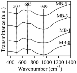 | ||
| Fig. 3 FTIR transmittance spectra of investigated glasses. | ||
Fig. 4 presents MAS-NMR spectra of the investigated glasses for 29Si (Fig. 4a) and 27Al (Fig. 4b) nuclei. The broad 29Si spectra of all the glasses imply a wide distribution of Qn (Si) units in their glass structures. No significant variations in the peak positions of 29Si and 27Al spectra could be observed, indicating the minimal effect of varying Bi2O3 on the glass structure. The 27Al spectra of the glasses demonstrate the dominance of tetrahedral coordinated aluminium in glasses, with its maxima at ∼62 ppm. It is well-known that the chemical shift in 27Al NMR spectrum is strongly affected by the local coordination of aluminium ions, therefore the 27Al NMR spectrum reflects the local structures of all the aluminium ions in the samples. An increase in the aluminium coordination number moves the chemical shift toward the lower end of the spectrum.30 The Al resonance in all the glasses exhibits a typical asymmetric shape with tails extending towards lower frequencies, resulting from the distributions in quadrupolar coupling constants.
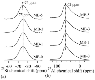 | ||
| Fig. 4 MAS-NMR spectra for (a) 29Si and (b) 27Al nuclei. | ||
3.3 Thermal analysis
| ln(β/TP) = −Ec/RTp + constant | (1) |
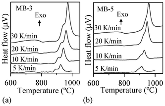 | ||
| Fig. 5 Typical DTA traces of investigated glasses at different heating rates. | ||
From the slope and the intercept of the plot given by eqn (1), one can derive the activation energy, Ec.
The most commonly used method to investigate surface and volume crystallization is based on differential thermal analysis and was proposed by Ray and Day32 and Augis–Bennett.31 The method considers the temperature corresponding to the maximum crystallization peak, TP, the maximum intensity of the DTA crystallization peak and the ratio TP/(ΔTP), where (ΔTP) is the peak half-width as a function of size of the glass particles. The crystal growth dimension n, also considered as an Avrami parameter, is defined by
| n = 2.5RTP2/EΔTP | (2) |
Fig. 6 displays the slopes of the straight lines ln(β/Tp) vs. 1/Tp for the first and second exothermic peaks. The calculated Ec and n values are listed in Table 5. It can be seen that Ec for the first crystallization peak increased from ∼612 kJ mol−1 for the parent glass composition to ∼651 kJ mol−1 upon adding 1 wt% Bi2O3 (an increment of about 6%). On the other hand, further incremental amounts of Bi2O3 caused significant decreases (∼21–27%) in Ec. Similar trends were also observed for the Ec corresponding to the second crystallization peak, but the absolute values were somewhat lower. The values of the Avrami parameter (n) varied roughly between 2–3 for the first crystallization peak, and in the range of 1–3 for the second crystallization peak (Table 5). For MB–0 glass, the Ec and n values of both crystallization peaks are in good agreement with those reported by Orisini et al.12 for pure melilite glasses. The n values for the first peak suggest that, for MB–0 and MB–1 glasses, crystallization did not occur on a fixed number of nuclei and that the crystalline phase, merwinite, grew by simultaneous surface and internal crystallization, while, for MB–3 and MB–5 glasses, three-dimensional bulk nucleation occurred. In the case of the second exothermic peak, the crystal growth mechanism gradually changed from surface to bulk nucleation with increasing additions of Bi2O3.33 As proposed by Orisini et al.12 for melilite glasses, the mechanism of merwinite growth must be related to the transport of Al3+ ions through the phase boundary, as well as to its later distribution in the parent phase.
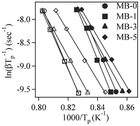 | ||
| Fig. 6 Plots for ln(β/Tp) vs. 1/Tp (filled and open symbols represent first and second exothermic peaks, respectively). | ||
| MB–0 | MB–1 | MB–3 | MB–5 | |
|---|---|---|---|---|
| E c | ||||
| First | 612.66 | 650.79 | 486.46 | 448.58 |
| Second | 605.42 | 614.74 | 477.93 | 434.64 |
| n | ||||
| First | 2.3 | 1.8 | 2.5 | 2.7 |
| Second | 1.1 | 1.6 | 2.0 | 2.5 |
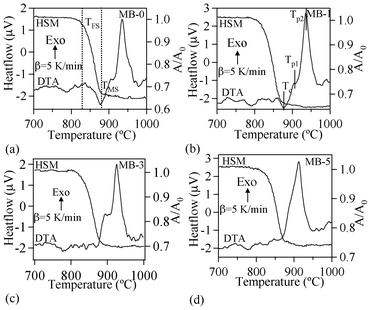 | ||
| Fig. 7 DTA-HSM thermo graphs of the investigated glasses at 5 K min−1. | ||
Table 4 summarizes the values of TFS (logη = 9.1 ± 0.1; η is viscosity in dPa s), TMS (log η = 7.8 ± 0.1) and A/A0, as obtained from the HSM data at TMS (Fig. 7), along with Tc and Tp obtained from DTA of the glasses. The following observations can be made from the DTA and HSM results: TFS, obtained from HSM, firstly decreased from 820 to 800 °C upon adding 1 wt% Bi2O3 and then varied between 800–825 °C with further increases in Bi2O3 content from 1 to 5 wt%. Similar trends were also observed in the case of TMS.
Single stage maximum shrinkage behaviour was observed for all the glasses as shown in Fig. 7. In all glass compositions, except MB–1 (Fig. 7b), crystallization starts before complete densification, i.e., TMS > Tc. In the case of MB–1 glass TMS < Tc, which explains the achievement of complete densification before the onset of crystallization, resulting in well sintered and dense glass powder compacts. Usually, if crystallization precedes sintering, the final glass-ceramic can be highly porous and exhibit poor mechanical properties.
In accordance with HSM and DTA data (Fig. 7), complete sintering was expected to be achieved only in composition MB–1.
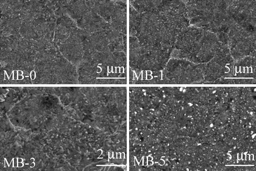
However, Table 6 shows that well-sintered dense glass-powder compacts were obtained for 2 compositions, i.e. MB–0 and MB–1 (shrinkage 13.83 and 14.47%, respectively) after heat treatment at 850 °C for 1 h. Sintering was less pronounced in MB–3 (shrinkage 12.67%) while a porous body was recorded in the case of MB–5 (shrinkage 9.82%). Both density and shrinkage were enhanced by further increasing the heat treatment temperature, especially for MB–5. Although most of porosity observed in MB–3 and MB–5 was eliminated upon heat treating at 900 °C, some micro porosity still remained, as can be seen in Fig. 8.
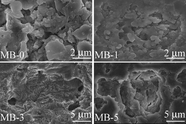 | ||
| Fig. 8 Microstructure (revealed via SEM imaging of polished surfaces after chemical etching with 2 vol% HF solution) of the GCs heat treated at 900 °C for 1 h. | ||
| 850 °C | 900 °C | |
|---|---|---|
| Shrinkage | ||
| MB–0 | 13.83 ± 0.03 | 14.77 ± 0.25 |
| MB–1 | 14.47 ± 0.16 | 15.75 ± 0.08 |
| MB–3 | 12.67 ± 0.10 | 14.00 ± 0.18 |
| MB–5 | 9.82 ± 0.11 | 14.45 ± 0.17 |
| Density | ||
| MB–0 | 3.005 ± 0.006 | 3.093 ± 0.004 |
| MB–1 | 2.978 ± 0.001 | 3.047 ± 0.001 |
| MB–3 | 3.071 ± 0.004 | 3.074 ± 0.009 |
| MB–5 | Porous body | 3.057 ± 0.006 |
3.4 Crystallization behaviour and properties of sintered glass-ceramics:
The qualitative evolution of crystalline phases in the glass-powder compacts sintered at 850 and 900 °C is demonstrated in the XRD patterns shown in Fig. 9a and 9b. The standard diffraction patterns of merwinite (Ca3Mg(SiO4)2; ICDD: 35–0591), akermanite–gehlenite (ICDD: 76–7527) and calcium lanthanum oxysilicate (CaLa4(SiO4)3O; ICDD: 08–8013) are also presented for comparison. Merwinite was identified as a minor crystalline phase in the GCs sintered at 850 °C, along with the major glassy phase. The crystallization was enhanced by increasing the sintering temperature to 900 °C, resulting in the formation of akermanite–gehlenite as a major phase, and merwinite and calcium lanthanum oxysilicate as secondary phases. The strongest peak at 2θ = 33.32° in the GCs sintered at 850 °C corresponds to merwinite, while the peak at 2θ = 31.42° in GCs sintered at 900 °C belongs to akermanite–gelhinte. This means that the first DTA exothermic peak is due to merwinite formation, while the second one is due to the crystallization of the akermanite–gehlenite phases. Table 7 presents the qualitative, as well as quantitative, analysis of the crystalline phases present in all the investigated GCs, as obtained from XRD analysis used with Rietveld-RIR technique. Fig. 10a and 10b show the measured XRD pattern fits for GCs sintered at 850 °C and 900 °C, respectively, by using the GSAS EXPGUI software. The calculated diagrams are based on crystallographic structure models, which also take into account specific instrument and sample effects. The parameters of this model have been refined simultaneously using a least-squares methods in order to obtain the best fit to all measured data. By least-squares refinement, a so-called figure-of-merit function, R, has been defined, which describes the residual (agreement) between observed and calculated data.34 It is noteworthy that many different statistical R factors have been proposed for judging the quality of a Rietveld refinement. These R factors show the mean deviation in accordance with the model used in percent. The “profile R-factor”, Rp, and “weighted profile R-factor”, Rwp, for all the refinements are presented in Table 7. The values of Rwp as obtained in the present investigation are well within the limits of experimental accuracy. The difference plots in Fig. 10a and 10b do not show any significant misfits. The differences between the main peaks of merwinite and akermanite–gehlenite are caused by adjustment difficulties based on the crystallinity of the phases. The chemical composition of the sintered GCs heat treated in a H2-containing atmosphere for 100 h is very similar to that of the initial glasses, and is within the limits of standard experimental error for the ISP-OES technique (Table 2). In particular, Bi2O3 losses are insignificant. This makes it possible to expect negligible losses of bismuth oxide during sealing and subsequent operation of the electrochemical cells. The same conclusion was drawn from the EDX analysis. The surface and bulk compositions of the sintered GCs heat treated in a humidified flowing 10% H2:90% N2 gas mixture for 100 h were found to be equal to those of the initial glass powder, within the limits of experimental uncertainty, confirming a stable and homogeneous distribution of bismuth oxide dissolved in the GC sealant.
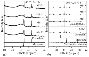 | ||
| Fig. 9 XRD pattern of GCs sintered for 1 h at: (a) 850 °C; (b) 900 °C. | ||
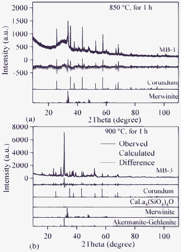 | ||
| Fig. 10 Observed (crosses), calculated (continuous line), and difference curve from the Rietveld refinement of the GCs heat treated for 1 h in air at: (a) 850 °C; (b) 900 °C. | ||
| 850 °C for 1 h | 900 °C for 1 h | |||||||
|---|---|---|---|---|---|---|---|---|
| MB–0 | MB–1 | MB–3 | MB–5 | MB–0 | MB–1 | MB–3 | MB–5 | |
| Ca2Mg0.54 Al0.92 Si1.54O7 | — | — | — | — | 56.90 | 74.98 | 65.31 | 73.23 |
| Ca3Mg (SiO4)2 | 14.5 | 14.4 | 30.7 | 48.0 | 14.67 | 09.04 | 05.81 | 07.67 |
| CaLa4 (SiO4)3O | — | — | — | — | — | 04.60 | 05.72 | 07.36 |
| Glass | 85.5 | 85.6 | 69.3 | 52.0 | 28.43 | 11.38 | 23.16 | 11.74 |
| χ 2 | 3.20 | 2.71 | 3.982 | 1.91 | 4.743 | 4.48 | 3.84 | 4.06 |
| R wp | 0.097 | 0.088 | 0.105 | 0.076 | 0.120 | 0.117 | 0.105 | 0.107 |
| R p | 0.074 | 0.066 | 0.078 | 0.053 | 0.090 | 0.087 | 0.079 | 0.080 |
3.5 Interaction with metallic interconnects:
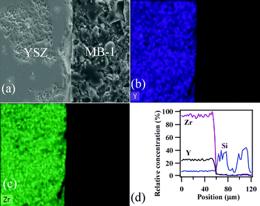
To achieve gas-tight sealing, the glass should be able to bond well to the adjoining materials and have a high interfacial stability with other components of the electrochemical devices. All the sealing GCs bonded well to 8YSZ electrolyte. It is known that GCs generally show higher chemical stability than glasses, and thus are expected to have few or no chemical reactions with zirconia and metallic alloys at high temperatures. Fig. 11 (a, c and d) shows the SEM images of the electrolyte/seal (8YSZ/GC) joints after heat treatment at 900 °C for 1 h in air for MB–1, MB–3 and MB–5, respectively. The EDS element mapping of the joint GC–MB–1/8YSZ is shown in Fig. 11b. Some voids that can be seen on the GC side of the SEM images are due to the removal of amorphous or crystalline material during mechanical grinding and polishing of interfaces. Fig. 12 presents the EDS elemental mapping for elements Y, Zr and Si, as well as the line profiles for these elements and Bi, along the interface of GC–MB–1/8YSZ electrolyte. As shown by element mapping (Fig. 12a, 12b and 12c) and line profiles (Fig. 12d), a rather smooth interface was obtained between the investigated GC seal and 8YSZ . Clearly, no diffusion of elements from the GC towards the 8YSZ electrolyte or vice versa occurred for the GCs fabricated from all four investigated glass compositions. For potential SOFC applications, interactions between glass sealants and metallic interconnects are even more important than with other components, thus attention has also been devoted to study of the seal glass–Sanergy HT interconnect interface. Among metallic interconnects, chromia-forming ferritic stainless steels and Sanergy HT are the most promising and widely used materials. Fig. 11e shows a SEM image of the interface between Sanergy HT/GC–MB–5 joint after heat treatment at 900 °C for 1 h in air. Fig. 13 presents the EDS elemental mapping for elements Cr, Fe and Mn (Fig. 13a, 13b and 13c), as well as the line profiles (Fig. 13d) for Cr, Mn, Al and Bi, along the interface of GC–MB–5/Sanergy HT. A rather smooth interface between GC–MB–5 and Sanergy HT was observed without the presence of iron-rich oxide products. However, as can be seen from Fig. 11f, a Mn- and Cr-rich oxide layer was formed at the steel side of the interface, indicating the formation of manganese–chromium spinel. The bonding/wetting behaviour of silicate glasses to an oxide layer on the metal surface promotes wetting, which is strongly dependent on the surface of the metal. The formation leads to improved chemical bonding. Further, no significant differences could be observed in the chemical interaction between GC sealants and electrolyte/metallic interconnects due to the addition of Bi2O3.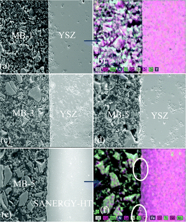 | ||
| Fig. 11 SEM images and EDS element mapping of the polished interfaces between GC–MB–1/8YSZ, (a) and (b); GC–MB–3/8YSZ, (c); GC–MB–5/8YSZ, (d), and GC–MB–5/Sanergy HT, (e) and (f). | ||
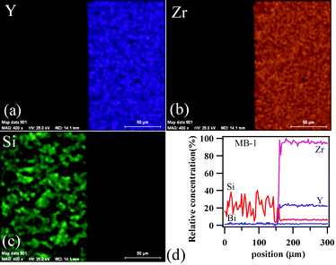 | ||
| Fig. 12 EDS element mapping for (a) Y, (b) Zr, (c) Si and (d) concentration profiles at the GC–MB–1/8YSZ interface heat treated at 900 °C for 1 h. | ||
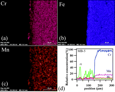 | ||
| Fig. 13 EDS element mapping for (a) Cr, (b) Fe, (c) Mn, and (d) concentration profiles at the GC–MB–5/Sanergy HT interface heat treated at 900 °C for 1 h. | ||
3.6 Thermal stability under air and humidified atmosphere
The qualitative and quantitative crystalline phase evolution after prolonged heat treatment of GCs at 900 °C for 300 h in an air atmosphere are presented in Fig. 14 and Table 8, respectively, and the corresponding microstructure SEM images are shown in Fig. 15. Akermanite–gehlenite (ICDD: 76–7527) and calcium lanthanum oxysilicate (CaLa4(SiO4)3O; ICDD: 08–8013) systems appeared as the primary and secondary crystallized phases respectively in all the GCs. However, it was remarkable that, after the long-term heat treatment, the merwinite crystalline phase completely disappeared from MB–1, MB–3 and MB–5 glasses, while merwinite remained as the secondary phase in MB–0. No significant effect (Table 7 and 8) on the quantity of akermanite–gehlenite SS and calcium lanthanum oxysilicate phases could be observed after long-term heat treatment compared to the GCs produced at 900 °C for 1 h.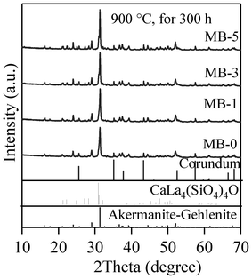 | ||
| Fig. 14 XRD pattern of GCs sintered at 900 °C for 300 h under an air atmosphere. | ||
 | ||
| Fig. 15 Microstructure (revealed via SEM imaging of polished surfaces after chemical etching with 2 vol% HF solution) of the GCs heat treated at 900 °C for 300 h. | ||
| 900 °C for 300 h | ||||
|---|---|---|---|---|
| MB–0 | MB–1 | MB–3 | MB–5 | |
| Ca2Mg0.54Al0.92 Si1.54O7 | 62.80 | 81.52 | 62.37 | 70.12 |
| Ca3Mg (SiO4)2 | 5.07 | — | — | — |
| CaLa4(SiO4)3O | 2.82 | 6.64 | 7.74 | 8.49 |
| Glass | 33.97 | 11.84 | 29.89 | 21.39 |
| χ 2 | 4.13 | 4.01 | 4.21 | 4.20 |
| R wp | 0.111 | 0.11 | 0.11 | 0.11 |
| R p | 0.083 | 0.08 | 0.08 | 0.08 |
Fig. 16 presents the SEM images and EDS elemental mapping along the interface of the GC/8YSZ electrolyte heat treated in air at 900 °C for 300 h and Fig. 17 presents those along the interfaces of the GC/8YSZ electrolyte and the GC/Sanergy HT under reducing atmosphere conditions at 850 °C for 100 h. Clearly, no diffusion of elements from the GC towards the 8YSZ electrolyte or vice versa occurred. With regard to GC/Sanergy HT diffusion couples after exposure in areducing atmosphere at 850 °C for 100 h , a reaction layer ca. 10 μm was formed at the GC–MB–3/Sanergy HT interface (Fig. 17f). This layer is rich in Cr- and Mn-oxides (Fig. 17g and 17h) similarly to that observed at the GC–MB–5/Sanergy HT interface (Fig. 13) heat treated at 900 °C for 1 h in air, but its thickness significantly increased in reducing conditions. In contrast, there is a significant interaction between Sanergy HT metallic plate and GCs (MB–0) under analogous conditions after long term heat treatment (Fig. 17a and 17b).
 | ||
| Fig. 16 (a) SEM image, EDS element mapping for (b) Y and (c) Zr, and (d) concentration profiles at the GC–MB–1/8YSZ interface heat treated at 900 °C for 300 h in air atmosphere. | ||
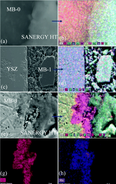 | ||
| Fig. 17 SEM images and EDS element mapping of the polished interfaces heat treated at 850 °C for 100 h in reducing atmosphere: GC–MB–0/Sanergy HT interface (a) and (b); GC–MB–1/8YSZ (c) and (d); GC–MB–3/Sanergy HT (e) and (f); (g) Cr and (h)Mn elemental mapping of the joint GC–MB–3/Sanergy HT. | ||
4 Discussion
Gehlenite and akermanite belong to the melilite group of silicates and form continuous solid solutions. Structures of solid solutions consist of tetrahedrons of SiO4, AlO4 and MgO4, which are bonded by Ca–O bonds in the entire structure. Isomorphic substitutions occur according to the scheme: Mg2+ + Si4+ = 2Al3+. In all experimental compositions the weight ratio of gehlenite to akermanite was taken as 50:50. Thus, experimental glasses were produced without difficulties at 1590 °C, considering the fact that gehlenite has a melting point at 1590 °C and akermanite melts at about 1450 °C.
It can be seen that the CTE (200–700 °C) of the glasses varied between 10.2–10.9 × 10⁻⁶ K−1. The small fluctuations in CTE values with minor additions of Bi2O3 may be due to rearrangements in the glass network structure as the CTE of glass is a function of temperature and composition. The bonding strength characteristics, and thus the structure of the glasses, are also expected to govern the CTE. The increase in Bi2O3 content gives rise to a decrease in the Si–O–Si bridging oxygen (BO) of the silicate structural unit, due to progressive formation of non-bridging oxygens (NBOs) and consequent depolymerization of the glass network.35,36 This leads to a gradual breakdown in the glass network, an increase in the CTE, and also explain the observed decrease in Tg from 800 to 789 °C (Table 3 and 4). Similar results were demonstrated by Singh et al.37 in the system K2O–B2O3–Bi2O3, in which the added low content of Bi2O3 broke the K–O–K and B–O–B bonds, thus converting BOs into NBOs. As a dynamic parameter, beyond the chemical composition, Tg also depends on the heating/cooling rate, being strongly associated with melting properties such as viscosity and shear modulus.
Concerning the glass structure, the FTIR transmittance band of a medium to strong intensity in the 600–750 cm−1 region with the centre of gravity at ∼685 cm−1 is a typical feature of alkaline glasses and implies the tetrahedral coordination of Al.27,28 Further, an increase in bismuth content in glasses did not affect either the major silicate band in the region of 800–1200 cm−1, or the tetrahedral coordination band in the region of 600–750 cm−1. This is well correlated with the results of Bishy et al.,38 according to whom Bi3+ ions participate in the glass network structure above 45 mol% Bi2O3. MAS-NMR 27Al spectra of glasses show the dominance of tetrahedral coordinated aluminium in glasses, with its maxima at ∼62 ppm, confirming the FTIR results. However, the presence of five/six-coordinated aluminium species cannot be neglected, as melilite has been reported to exist in a variety of calcium magnesium aluminosilicate glasses with varying Ca:Mg ratio.39 According to Murdoch et al.,40 an increase in the number of Al next-nearest neighbours to the SiO4 units de-shields the Si nucleus by 5.5 ppm per Al neighbour, on average. The 29Si peak position for the investigated glasses lies at ∼−75 ppm. A peak position in this range may represent highly polymerized species with many Al neighbours or less polymerized units with few or no Al neighbours.
Fujiomoto and Nakatsuka41 studied the effect of Bi2O3 concentration on Al coordination state in Bi-doped silicate glasses and concluded that: (i) the addition of Bi2O3 changes the aluminium coordination state from 6-fold to 5- or 4-fold coordination structure and (ii) the effect of Bi2O3 was stronger than that of Al2O3. In the present case, the decreasing activation energy and changing crystal growth mechanism with increasing Bi2O3 content might be also due to a decreasing population of AlO6 units. A detailed structural and thermal investigation on glasses with wide variation in Bi2O3:Al2O3 ratio will help in gaining a better insight into their structure–property relationships.
MB–1 glass (Table 4) has the lowest A/A0 value, which implies enhanced densification (95–98%). The same conclusion can be made for the composition of MB–0. Thus, adding 1 wt% Bi2O3 enhanced the sinter ability of the parent melilite glass MB–0, while further additions favoured the occurrence of devitrification before full densification was achieved. However, in the case of MB–3 and MB–5, devitrification hindered full densification and porosity remained in samples sintered at 850 °C. This increased tendency towards crystallization is probably due to a concomitant decrease in viscosity of the glasses, which might facilitate diffusion of cations. The decrease in Tg, and Tp values (Fig. 1 and 2) with increasing Bi2O3 content is in accordance with the results reported by Kim et al.42 The two exothermic crystallization peaks tend to overlap more with an increase in either the heating rate (Fig. 5) or the Bi2O3 content (Fig. 7), thus accentuating the congruent crystallization of the investigated glasses. As revealed from the XRD studies, the formation of the first exothermic peak corresponds to crystallization of merwinite phase and is mainly due to the high mobility of alkali earth ions.12 The gradual disappearance of this exothermic peak with increasing Bi2O3 content suggests that Bi3+ ions play a role in the flow properties of glass compositions.
Table 7 shows that the amount of merwinite formed in GCs sintered at 850 °C significantly increased with increasing additions of Bi2O3, while its presence was considerable reduced in GCs sintered at 900 °C. Further, with increasing Bi2O3, the CaLa4(SiO4)3O crystalline phase was promoted in GCs sintered at 900 °C for 1 h, as well as those sintered for 300 h (Table 7 and 8), and abridged the merwinite crystalline phase. These observations demonstrate the effective influence of Bi2O3 on crystallization and its role as an effective nucleating agent in this system. The significant increase in crystalline fraction observed in GCs sintered under various conditions (Table 7 and 8) with increasing amounts of Bi2O3 is in accordance with crystallization kinetic studies, which revealed lower activation energy for MB–5 glass in comparison to other compositions.
The CTE of GCs is known to depend on the densification degree, the type of crystalline phases formed and the glass content. In the present case, the CTE (200–700 °C) varied in the range of 9.8–11.2 × 10⁻⁶ K−1 (Table 9). For the GCs sintering at 900 °C for 1 h, a decrease in the CTE from 10.5 to 9.4 × 10⁻⁶ K−1 occurred with an initial addition of 1 wt.% Bi2O3, while further Bi2O3 increments gradually increased the CTE up to 11.2 × 10⁻⁶ K−1. The CTE values for all the GCs decreased after prolonged heat treatment in comparison to the GCs sintered at 900 °C for 1 h, due to the decrease in crystallinity of the GCs (Table 7 and 8), except in MB–1 glass where CTE value was increased. However, among the GCs sintered at 900 °C for 300 h, the highest CTE (200–700 °C) was shown by MB–1 (11.7 × 10⁻⁶ K−1), due to its high crystalline content, while the lowest was shown by MB–0 (9.9 × 10⁻⁶ K−1). Furthermore, the CTE values for the GCs sintered at 900 °C for 1 h and then annealed in a reducing atmosphere at 850 °C for 100 h are well-matched with the GCs produced under oxidising atmospheric conditions for 300 h at 900 °C (Table 9). Thus, CTE values of GCs sintered under various conditions are in good agreement with that of the ceramic electrolyte, 8YSZ (∼10 × 10−6 K−1) and metallic interconnect, Sanergy HT (∼11 × 10−6 K−1),43 considering that differences of up to 1 × 10⁻⁶ K−1 between the CTEs of SOFC components can be easily accommodated.
The densification behaviour of glasses correlates well with the results reported by Lo et al.,44 according to whom the sinter ability at lower temperature tends to degrade with the addition of Bi2O3, while the same compositions show good sinterability at higher temperatures, promoted by the viscous flow.
Regarding the applicability of synthesised GCs as sealants for high-temperature electrochemical devices, dense and low porosity materials with a high chemical stability are generally desired in order to obtain gas-tight seals. According to the EDS elemental mapping analysis of the joint GC–MB–3/Sanergy HT exposed to humidified hydrogen at 850 °C for 100 h (Fig. 17), the amounts of chromium and manganese in the preoxidation layer was high, but there was no extensive diffusion of these components into the sealant (Fig. 13 and 17e–h). An inter diffusion distance between seal glass and interconnect of ca. 10 μm was at the limit of its applicability.9 However, formation of manganese–chromium spinel on the steel surface is expected to be of some benefit, because it limits the chromium volatilization rate under the prospective operating conditions, given the fact that manganese–chromium spinel is less reactive and more stable than chromia against evaporation.10,45,46 Although chromium volatilization is decreased by manganese additions, it is not eliminated, so alloys that form scales with little or no chromium should be considered for further evaluation. For Cr-containing alloys, decreasing concentration of Bi2O3 down to the minimum possible is desirable, as bismuth oxide additive promotes the formation of an interfacial layer (Fig. 17). Therefore, good sintering ability, the desired CTE values, good wetting and their chemical stability make MB–0 and MB–1 glasses most promising for future long-term tests in solid-electrolyte electrochemical cells. The ICP-OES and EDX analyses, performed on the initial glass powder (MB–1, MB–3 and MB–5) and corresponding glass-ceramic compacts treated in reducing atmosphere for 100 h, showed that Bi2O3 concentration is homogeneous and stable throughout the material, suggesting an absence of deleterious effects of Bi2O3 on the cell performance.
Nevertheless, the three dimensional bulk nucleation occurring in Bi-richer glasses MB–3 and MB–5, as revealed by their early stage of crystallization,47,48 gives these glasses great potential interest for other applications in the field of GCs, such as layers for optical and electronic devices, thermal and mechanical sensors, reflecting windows, etc.49
5 Conclusions
The data presented and discussed throughout this manuscript enable the following conclusions to be drawn:1. Increasing amounts of Bi2O3 in melilite based glasses reduce the number of bridging Si–O–Si oxygens, leading to a gradual breakdown in the glass network, decreasing Tg, and Tp values and a concomitant increase in CTE.
2. Single stage maximum shrinkage behaviour was recorded for all the glasses. The sintering ability of the parent mililite glass, MB–0, was enhanced by adding 1 wt% Bi2O3, while further additions caused the opposite effect, with Bi2O3 acting as nucleating agent. Accordingly, Ec increased with the first addition of 1 wt% Bi2O3 and then significantly decreased (∼21–27%) with further Bi2O3 increments, as the crystallization growth mechanism gradually changes from surface to bulk. The decreasing activation energy values with increasing amounts of Bi2O3 are consistent with the higher amounts of crystalline phase formed in the GCs.
3. Well sintered and dense GCs with merwinite and akermanite–gehlenite as dominant crystalline phases were obtained upon sintering of glass powders for 1 h at 850 °C and 900 °C, respectively, whereas akermanite–gehlenite and calcium lanthanum oxysilicate phases were developed upon sintering at 900 °C for 300 h.
4. Compositions with very low Bi2O3 content, such as MB–1 and glasses free from Bi2O3 (e.g. MB–0), exhibiting appropriate CTE values, good sintering ability, and thermal and chemical stability in various external conditions satisfy most requirements of sealants for planar SOFCs and other electrochemical devices such as oxygen pumps. These compositions might therefore be considered for further investigation in SOFC stacks and other appliances with zirconia solid electrolytes, provided that good insulating electrical properties can be achieved.
Acknowledgements
This study was financially supported by the University of Aveiro, CICECO, and FCT, Portugal (PTDC/CTM-CER/114209/2009).References
- J. Larmine and A. Dicks, Fuel Cell Systems Explained; Wiley: New York, 2000 Search PubMed.
- S.C. Singhal and K. Kendall, High temperature solid oxide fuel cells: fundamentals. New York: Elsevier, 2000, p. 1–4 Search PubMed.
- EG & G Technical Services (2004) Fuel cell handbook, 7th edn US Department of Energy, Office of Fossil Energy, National Energy Technological Laboratory, pp 7–12.
- A. Goel, M. J. Pascual and J. M. F. Ferreira, Int. J. Hydrogen Energy, 2010, 35, 6911 CrossRef CAS.
- A. Goel, A. A. Reddy, M. J. Pascual, L. Gremillard, A. Malchere and J. M. F. Ferreira, J. Mater. Chem., 2012, 22, 10042 RSC.
- J. W. Fergus, J. Power Sources, 2005, 147, 46 CrossRef CAS.
- K. D. Meinhardt, D. S. Kim, Y. S. Chou and K. S. Weil, J. Power Sources, 2008, 182, 188 CrossRef CAS.
- Z. Yang, J. W. Stevenson and K. D. Meinhardt, Solid State Ionics, 2003, 160, 213 CrossRef CAS.
- M. K. Mahapatra and K. Lu, Mater. Sci. Eng., R, 2010, 67, 65 CrossRef.
- F. Smeacetto, A. Chrysanthou, M. Salvo, Z. Zhang and M. Ferraris, J. Power Sources, 2009, 190, 402 CrossRef CAS.
- Y. S. Chou, J. W. Stevenson and J. P. Choi, J. Electrochem. Soc., 2010, 157, B348 CrossRef CAS.
- P. G. Orsini, A. Buri and Marotta, J. Am. Ceram. Soc., 1975, 58, 306 CrossRef CAS.
- J. Gillot, M. Roskosz, H. Leroux, F. Capet and P. Roussel, J. Non-Cryst. Solids, 2011, 357, 3467 CrossRef CAS.
- P. B. Moore and A. Takaharu, Ame. Mineraloaist, 1972, 57, 1355 CAS.
- K. Keizer, M. J. Verkerk and A. J. Burggraaf, Ceramurgia International, 1979, 5, 143 CrossRef CAS.
- A. Chakraborty and H. S. Maiti, Ceram. Int., 1999, 25, 115 CrossRef CAS.
- V. V. Kharton, E. N. Naumovich and A. A. Vecher, J. Solid State Electrochem., 1999, 3, 61 CrossRef CAS.
- H. Zhong, X. Zhou, X. Liu and G. Meng, J. Rare Earths, 2005, 23, 36 Search PubMed.
- V. Gil, J. Tartaj, C. Moure and P. Duran, Ceram. Int., 2007, 33, 471 CrossRef CAS.
- B. Bai, N. M. Sammes and A. L. Smirnova, J. Power Sources, 2008, 176, 76 CrossRef CAS.
- J.-K. Lee, H.-S. Park and G.-S. Yang, Korean J. Mater. Res., 2008, 18, 283 CrossRef CAS.
- J. Fouletier and V. Ghetta, High-Temperature Applications of Solid Electrolytes: Fuel Cells, Pumping, and Conversion. In: Solid State Electrochemistry I: Fundamentals, Materials and their Applications, Ed. V. Kharton. Wiley-VCH: Weinheim, 2009, pp. 397–426 Search PubMed.
- H. Scholze, Ver: Dtsch. Kerom. Ges., 1962, 391, 63 Search PubMed.
- M. J. Pascual, M. O. Prado and A. Duran, Phys. Chem. Glasses, 2005, 46, 512 CAS.
- N. Ahlawat, S. Sanghi, A. Agarwal and R. Bala, J. Mol. Struct., 2010, 963, 82 CrossRef CAS.
- O. V. Mazurin, Glass Phys. Chem., 2007, 33, 22 CrossRef CAS.
- W. R. Taylor, Proc. Indian Acad. Sci., 1990, 99, 99 CAS.
- P. Tarte, Spectrochim. Acta, Part A, 1967, 23, 2127 CrossRef CAS.
- S. K. Sharma Jr., H. S. Yoder and D. W. Matson, Geochim. Cosmochim. Acta, 1988, 52, 1961 CrossRef.
- J. P. Laussac, R. Enjalbert, J. Gray and J. P. Laurent, J. Coord. Chem., 1983, 12, 133 CrossRef CAS.
- J. A. Augis and J. E. Bennett, J. Therm. Anal., 1978, 13, 283 CrossRef CAS.
- C. S. Ray and D. E. Day, Thermochim. Acta, 1996, 280, 163 CrossRef.
- S. Mahadevan, A. Giridhar and A. K. Singh, J. Non-Cryst. Solids, 1986, 88, 11 CrossRef CAS.
- R. A. Young, Introduction to the Rietveld method. In: Young RA, editor. The Rietveld method. International Union of Crystallography Monographs on Crystallography, vol. 5. Oxford: Oxford University Press, 1993, p. 1–39 Search PubMed.
- A. K. Varshneya, Fundamentals of inorganic glasses. Society of Glass Technology, Sheffield, 2006, p. 682 Search PubMed.
- M. I. Ojovan and W. E. Lee, J. Non-Cryst. Solids, 2010, 356, 2534 CrossRef CAS.
- S. P. Singh and B. Karmakar, Mater. Charact., 2011, 62, 626 CrossRef CAS.
- A. Bishay and C. Maghrabi, Phys. Chem. Glasses, 1969, 10, 1 CAS.
- K. E. Kelsey, J. R. Allwardt and J. F. Stebbins, J. Non-Cryst. Solids, 2008, 354, 4644 CrossRef CAS.
- J. B. Murdoch, J. F. Stebbins, I. S. E. Carmichael and A. Pines A, Phys. Chem. Miner., 1988, 15, 370 CrossRef CAS.
- Y. Fujimoto and M. Nakatsuka, J. Non-Cryst. Solids, 2006, 352, 2254 CrossRef CAS.
- B. Kim, E. Lim, J. Lee and J. Kim, J. Eur. Ceram. Soc., 2007, 27, 819 CrossRef CAS.
- A. Goel, D. U. Tulyaganov, V. V. Kharton, A. A. Yaremchenko, S. Eriksson and J. M. F. Ferreira, J. Power Sources, 2009, 189, 1032 CrossRef CAS.
- S. Lo and C. Yang, Ceram. Int., 1998, 24, 139 CrossRef CAS.
- F. Smeacetto, M. Salvo, M. Ferraris, V. Casalegno and P. Asinari, J. Eur. Ceram. Soc., 2008, 28, 611 CrossRef CAS.
- K. Fujita, et al. , J. Power Sources, 2004, 131, 270 CrossRef CAS.
- R. G. Hill, M. D. O'Donnell, R. V. Law, N. Karpukhina, B. Cochrane and D. U. Tulyaganov, J. Non-Cryst. Solids, 2010, 356, 2935 CrossRef CAS.
- S. M. Abo-Naf, R. L. Elwan and G. M. Elkomy, J. Non-Cryst. Solids, 2012, 358, 964 CrossRef CAS.
- C. Stehle, C. Vira, D. Vira, D. Hogan, S. Feller and M. Affatigato, Phys. Chem. Glasses, 1998, 39, 83 CAS.
| This journal is © The Royal Society of Chemistry 2012 |