One-step fabrication of hierarchically ordered structures on photoresponsive azobenzene-containing polymers with phase masks†
Si
Wu
* and
Jintang
Huang
*
Max Planck Institute for Polymer Research, Ackermannweg 10, 55128 Mainz, Germany. E-mail: wusi@mpip-mainz.mpg.de; huang@mpip-mainz.mpg.de
First published on 29th October 2012
Abstract
Hierarchically ordered structures are fabricated by laser irradiation on azobenzene-containing polymers through PDMS phase masks. The longer and shorter length scale structures of the hierarchical structures are interference patterns and self-organized nanostructures, respectively. The hierarchical structures are tunable by using different masks or changing the polarization of the laser.
Hierarchically ordered structures with complex features over several length scales have attracted considerable attention because they show promising applications in photonic crystals, superhydrophobic surfaces, solar collectors and surface-enhanced Raman scattering.1–6 One of the most well-known examples is hierarchically ordered structures on wings of Morpho butterflies, which show brilliant structural colors and can be used as sensors.1,2 Hierarchically ordered structures are often difficult to fabricate. They are usually fabricated by either a multistep procedure or replication from natural hierarchical structures such as structures on Morpho butterflies. However, these two methods have obvious drawbacks. Multistep procedures are tedious and make the structure formation very complex and less reliable. Replication can only obtain the same or the inverse structures of the templates, which cannot satisfy the demand for tunable hierarchical structures in many applications. So, it is highly desirable to use simple and efficient methods to fabricate hierarchically ordered structures with tunable morphology.
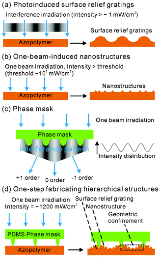
Here, we report one-step fabrication of hierarchically ordered structures with tunable morphology on photosensitive azobenzene-containing polymers (azopolymers) with phase masks. Fabrication of hierarchical structures is based on photofluidization of azopolymers. The term “photofluidization” comes from the phenomenon that the slopes of the load–penetration curves of azopolymer films decrease under light irradiation.7 Photofluidization means that the behavior of azopolymers under light irradiation is liquid-like.7 The photofluidization of azopolymers is caused by repeated trans-cis-trans photoisomerization which can soften azopolymers.7,8 This property has been recently used as a lithography method to fabricate micro- and nanostructures.8–10 Azopolymers show two kinds of photofluidic properties under different irradiation conditions: (1) Fig. 1a shows that surface relief gratings can be induced by interference irradiation with a moderate intensity (intensity > ∼1 mW cm−2).8,11–13 Azopolymers move from bright interference fringes (high intensity areas) to dark interference fringes (low intensity areas) by interference irradiation.8,11–13 (2) Fig. 1b shows that one-beam irradiation with an intensity higher than the threshold (in the order of ∼102 mW cm−2) can induce self-organized nanostructures on azopolymers.8,14–20
 | ||
| Fig. 1 Schematic illustrations of photoinduced surface relief gratings (a), one-beam-induced nanostructures (b), and a phase mask (c). The interference pattern near the phase mask is generated by interference of 1, 0 and −1 order diffracted beams. (d) Schematic illustration of one-step fabrication of hierarchical structures on azopolymers. | ||
In this paper, we integrate the two properties in Fig. 1a and b in one step by the phase mask approach. Fig. 1c shows the schematic illustration of a phase mask. A phase mask is a transparent periodic pattern. When a laser beam passes through a phase mask, the diffracted beams interfere near the surface of the phase mask. The intensity distribution of light can be modulated using the grating parameters of the phase mask.21–24 Unlike conventional laser interference lithography, which requires multiple beams with additional optical elements to generate periodic structures, the optical setup of the phase mask approach is very simple and equally promising for the fabrication of periodic structures.21–24Fig. 1d shows the process of fabrication of hierarchical structures on azopolymers. The hierarchical structure is generated by irradiation of the azopolymer film through the PDMS phase mask. In the hierarchical structure, the surface relief grating (interference pattern) is the longer length scale structure and the self-organized nanostructure is the shorter length scale structure.
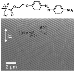
The azopolymer P2NO2 is used in this work (Fig. 2). P2NO2 was synthesized according to our previous work.25,26 A PDMS phase mask was put on the surface of the P2NO2 film without additional pressure. A linearly polarized laser at 446 nm with an intensity ∼1.2 W cm−2 was used to irradiate P2NO2 through the phase mask. After laser irradiation, the morphology of the azopolymer film was observed by scanning electron microscopy (SEM). The experimental details are described in the ESI.†
 | ||
| Fig. 2 The chemical structure of the azopolymer P2NO2 (top) and the SEM image of P2NO2 after one beam irradiation for 10 min (bottom). The arrow indicates the polarization (E vector) of the laser. | ||
We first studied one-beam-induced nanostructures on P2NO2. Fig. 2 shows the SEM image of P2NO2 after one beam irradiation for 10 min. P2NO2 forms self-organized nanoripples. The period of the nanoripples is 391 ± 13 nm and the nanoripples are 60 ± 4° to the polarization direction (E vector) of the laser beam. One-beam-induced self-organized nanostructures on different azobenzene-containing materials have been observed by several groups.8,14–20 In different cases, the directions of the nanoripples to the polarization direction of the laser could be 0°,19 60°,17,18 or 90°.20 For example, Wang et al. reported that the direction of nanoripples is 60° to the polarization direction of the laser.17,18 Our result in Fig. 2 is in accordance with theirs. Although the mechanism of one-beam-induced self-organized nanostructures is still not clear, this property can be applied to fabricate nanostructures.8,14–20
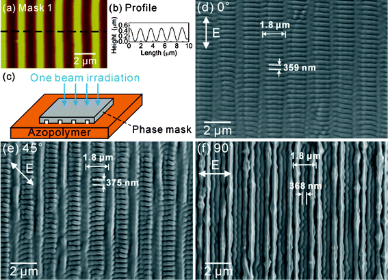
We integrated one-beam-induced nanostructures and surface relief gratings by the phase mask approach. Fig. 3a and b show the AFM image and profile of the PDMS phase mask (Mask 1). The profile of Mask 1 is sinusoidal. The period and surface relief of Mask 1 are 1.8 μm and ∼500 nm, respectively. Fig. 1c shows the setup of the phase mask approach. P2NO2 is irradiated by a laser beam through the phase mask. In different experiments, the polarizations of the laser beam to the grating direction (parallel to the lines of the interference pattern) of Mask 1 were 0°, 45° or 90°. The corresponding SEM images of P2NO2 after laser irradiation for 10 min are shown in Fig. 3d–f. Hierarchical structures are formed on P2NO2. In the hierarchical structures, the longer length scale structures are gratings with a period of 1.8 μm. All the gratings are aligned with the lines of Mask 1. Computer simulation shows that the interference pattern generated by Mask 1 is a line pattern with a period of 1.8 μm (ESI†). So, the longer length scale structures are interference patterns. The shorter length scale structures of the hierarchical structures in Fig. 3d–f are nanoripples with a period of ∼359–375 nm, which are compatible with the one-beam-induced nanoripples in Fig. 2.
 | ||
| Fig. 3 AFM image (a) and profile (b) of the PDMS phase mask with line patterns (Mask 1). (c) Schematic illustration of the one-step fabrication of hierarchical structures. (d)–(f) SEM images of hierarchical structures on the azopolymer P2NO2 fabricated by the linearly polarized laser with different polarizations (E vector). The arrows in (d)–(f) show the polarization (E vector) of the laser. Note: The grating direction is defined as the direction which is parallel to the lines of Mask 1. | ||
We also irradiated P2NO2 with polarizations 30° and 60° to the lines of Mask 1 (ESI,† Fig. S3). When the irradiation polarization is 30°, nanoripples are perpendicular to the lines of the grating. When the irradiation polarization is 60°, nanoripples are parallel to the lines of the grating.
Fig. 3 and Fig. S3† show that the polarization of the laser beam affects the structures. The polarizations of the incident laser beam and the diffracted beams are the same (ESI†). So, the polarization distributions of interference patterns are different when the polarization of the incident beam is different (ESI†). The nanoripples in Fig. 3d, 3e, and Fig. S3a† are almost perpendicular to the interference pattern. The nanoripples in Fig. 3f and Fig. S3b† are parallel to the interference pattern. Because the mechanism of one-beam-induced self-organized nanostructures is not clear, it is difficult to explain the mechanism of formation of the nanoripples in the hierarchical structures. However, the results in Fig. 3 and Fig. S3† clearly show that the orientation of the nanoripples is tunable by changing the polarization.
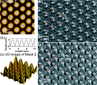
The longer length scale structure in the hierarchical structure is also tunable by using different phase masks. We used another mask (Mask 2) with hexagonal islands. AFM images and profiles in Fig. 4a–c show that the period and surface relief of Mask 2 are 2.2 μm and ∼1 μm, respectively. The tops of the islands, which are labeled with red circles in Fig. 4c, should contact with the azopolymer film during irradiation. The hierarchical structure in Fig. 4d was fabricated by the linearly polarized laser with polarization 0°. The red circles in Fig. 4d show that the packing and period of the double protuberant structures are the same as those of the islands of Mask 2. So, the array of the double protuberant structures are the interference patterns of Mask 2. The mechanism of formation of the double protuberant structures is explained in Fig. 1d. The islands of the mask contact with P2NO2. During irradiation, mass transport of P2NO2 happens and the islands of Mask 2 are embedded in P2NO2. Gaps between double protuberant structures form after removing Mask 2. We observed similar gaps when Mask 1 was used. In Fig. 3d–f, there are perpendicular gaps between two groups of nanoripples, which should be the locations of the tops of Mask 1. Gaps are just like the imprinting of phase masks. Fig. 4d also shows that the nanoripples are formed among the double protuberant structures.
 | ||
| Fig. 4 AFM image (a), profile (b) and 3D AFM image (c) of the PDMS phase mask with hexagonal islands (Mask 2). SEM images of hierarchical structures on the azopolymer P2NO2 fabricated by the linearly polarized laser with the polarizations (E vector) 0° (d) and 90° (e). The arrows in (d) and (e) indicate the polarization (E vector) of the laser. The red circles in (c) indicate the packing of the islands on Mask 2. The red circles in (d) and (e) indicate the contact points of Mask 2 and the azopolymer film. | ||
We fabricated another hierarchical structure with Mask 2 by changing the polarization of the laser to 90° (Fig. 4e). The structure in Fig. 4e is a very complex three-dimensional-like structure. We also observed double protuberant structures (labeled with red circles in Fig. 4e). The packing and period of the double protuberant structures are the same as those of the islands on Mask 2. However, the structure in Fig. 4e is different from that in Fig. 4d. This result shows again that the hierarchical structure is tunable by changing the polarization.
It is well known that the mass transport of azopolymers under interference irradiation is strongly polarization-dependent.11,12 For example, surface relief gratings fabricated by (p, p) interference beams are much higher than those fabricated by (s, s) interference beams.11,12 So, the polarization-dependent hierarchical structures can be explained by the polarization-dependent mass transport of azopolymers.
We compared nanoripples obtained at different irradiation conditions (Table S1, ESI†). The directions of the nanoripples are dependent on the polarization of the laser. The nanoripples obtained by one beam irradiation (Fig. 2) are without long range order. The nanoripples obtained with Mask 1 (Fig. 3) are highly ordered. The nanoripples obtained with Mask 2 (Fig. 4) are less ordered.
It is reported that periodic structures can be fabricated by phase masks.21–24,27 We compared our structures with the structures fabricated by the phase mask approach reported in the literature. The periodic structures reported in the literature have only one length scale (interference pattern). The periodic structures in this work have two length scales.
We also compared the structures fabricated by the phase mask approach with the structures fabricated by the conventional two-beam interference approach reported in the literature. Ciuchi et al. showed that two-beam interference can generate hierarchical structures with different morphologies on azopolymers.20 Yin et al. used two-beam interference to fabricate hierarchical structures on azo-containing materials.16 They showed that the nanoripples (shorter length scale structures) are randomly packed.16 Lee et al. also used two-beam interference to fabricate hierarchical structures on azopolymers.28 They obtained hierarchically ordered structures and the orientation of the nanoripples are always perpendicular to the surface relief gratings.28 In this work, we showed that the phase mask approach is very convenient for fabricating hierarchical structures with tunable longer and shorter length scale structures. A major difference between the phase mask approach and the conventional laser interference approach is that the phase mask directly contacts with the azopolymer. This difference affects the formation of structures. Firstly, the phase mask affects the longer length scale structures. The surface relief structures fabricated by the phase mask method are arrays of double protuberant structures (e.g., Fig. 4d), which are different from the normal surface relief structures fabricated by the conventional laser interference approach. Secondly, the phase mask also affects the shorter length scale structures. The contact parts of the phase mask and the azopolymer may confine the mass transport of azopolymers. It is well known that confinements can guide self-assembly of block copolymers, colloidal particles and liquid crystals, resulting in ordered nanostructures.29,30Fig. 1d shows that the phase mask creates geometric confinements on the azopolymer. When the phase mask is embedded into the azopolymer by irradiation, the azopolymers are confined in the microstructures of the phase mask. When Mask 1 is used (Fig. 3), the azopolymers are divided into strips by Mask 1 and ordered nanoripples are obtained. When Mask 2 is used (Fig. 4), the contact points are isolated islands and azopolymers are still continuous. Azopolymers are not really strongly confined by Mask 2 and less ordered structures are obtained. So, the geometrical confinement of phase masks should be a reason for the formation of ordered nanoripples.
In conclusion, we demonstrated one-step fabrication of hierarchical structures by the phase mask method. Our method has the following advantages. Firstly, it is an inexpensive and convenient method. We use an inexpensive diode laser as the light source and PDMS stamps as masks, which are easily obtained in laboratories or commercially available. The setup does not contain additional optical elements, so it is very easy to handle and convenient to users. Secondly, this method is very efficient. The hierarchical structures are fabricated within 10 min using only one step. Thirdly, the hierarchical structures are tunable by changing the polarization of the laser and the geometry of the phase mask. Although the effects of phase masks are not fully understood and need further investigation, the phase mask method already has many advantages for fabricating tunable hierarchical structures.
Acknowledgements
S.W. and J.H. were supported by the joint program of the Max Planck Society and the Chinese Academy of Sciences. We thank Prof. C. Bubeck for helpful discussions.References
- R. A. Potyrailo, H. Ghiradella, A. Vertiatchikh, K. Dovidenko, J. R. Cournoyer and E. Olson, Nat. Photonics, 2007, 1, 123–128 CrossRef CAS.
- A. D. Pris, Y. Utturkar, C. Surman, W. G. Morris, A. Vert, S. Zalyubovskiy, T. Deng, H. T. Ghiradella and R. A. Potyrailo, Nat. Photonics, 2012, 6, 195–200 CrossRef CAS.
- O. Sato, S. Kubo and Z. Z. Gu, Acc. Chem. Res., 2009, 42, 1–10 CrossRef CAS.
- Y. W. Tan, J. J. Gu, X. N. Zang, W. Xu, K. C. Shi, L. H. Xu and D. Zhang, Angew. Chem., Int. Ed., 2011, 50, 8307–8311 CrossRef CAS.
- Q. B. Zhao, X. M. Guo, T. X. Fan, J. Ding, D. Zhang and Q. X. Guo, Soft Matter, 2011, 7, 11433–11439 RSC.
- M. Kolle, P. M. Salgard-Cunha, M. R. J. Scherer, F. M. Huang, P. Vukusic, S. Mahajan, J. J. Baumberg and U. Steiner, Nat. Nanotechnol., 2010, 5, 511–515 CrossRef CAS.
- P. Karageorgiev, D. Neher, B. Schulz, B. Stiller, U. Pietsch, M. Giersig and L. Brehmer, Nat. Mater., 2005, 4, 699–703 CrossRef CAS.
- S. Lee, H. S. Kang and J. K. Park, Adv. Mater., 2012, 24, 2069–2103 CrossRef CAS.
- S. Lee, J. Shin, Y. H. Lee, S. Fan and J. K. Park, Nano Lett., 2010, 10, 296–304 CrossRef CAS.
- S. Lee, H. S. Kang and J. K. Park, Adv. Funct. Mater., 2011, 21, 1770–1778 CrossRef CAS.
- A. Natansohn and P. Rochon, Chem. Rev., 2002, 102, 4139–4175 CrossRef CAS.
- K. G. Yager and C. J. Barrett, In Polymeric Nanostructures and their Applications, Edited by: Nalwa, H. S.Los Angeles: American Scientific Publishers. Chapter 8, 2006 Search PubMed.
- D. Y. Kim, S. K. Tripathy, L. Li and J. Kumar, Appl. Phys. Lett., 1995, 66, 1166–1168 CrossRef CAS.
- C. Hubert, C. Fiorini-Debuisschert, I. Maurin, J. M. Nunzi and P. Raimond, Adv. Mater., 2002, 14, 729 CrossRef CAS.
- C. Hubert, C. Fiorini-Debuisschert, L. Rocha, P. Raimond and J. M. Nunzi, J. Opt. Soc. Am. B, 2007, 24, 1839–1846 CrossRef CAS.
- J. J. Yin, G. Ye and X. G. Wang, Langmuir, 2010, 26, 6755–6761 CrossRef CAS.
- X. L. Wang, J. J. Yin and X. G. Wang, Macromolecules, 2011, 44, 6856–6867 CrossRef CAS.
- X. L. Wang, J. J. Yin and X. G. Wang, Langmuir, 2011, 27, 12666–12676 CrossRef CAS.
- S. Lee, J. Shin, H. S. Kang, Y. H. Lee and J. K. Park, Adv. Mater., 2011, 23, 3244 CrossRef CAS.
- F. Ciuchi, A. Mazzulla, G. Carbone and G. Cipparrone, Macromolecules, 2003, 36, 5689–5693 CrossRef CAS.
- S. Jeon, J. U. Park, R. Cirelli, S. Yang, C. E. Heitzman, P. V. Braun, P. J. A. Kenis and J. A. Rogers, Proc. Natl. Acad. Sci. U. S. A., 2004, 101, 12428–12433 CrossRef CAS.
- C. H. Chang, L. Tian, W. R. Hesse, H. Gao, H. J. Choi, J. G. Kim, M. Siddiqui and G. Barbastathis, Nano Lett., 2011, 11, 2533–2537 CrossRef CAS.
- N. Kurra, A. A. Sagade and G. U. Kulkarni, Adv. Funct. Mater., 2011, 21, 3836–3842 CrossRef CAS.
- J. Park, J. H. Park, E. Kim, C. W. Ahn, H. I. Jang, J. A. Rogers and S. Jeon, Adv. Mater., 2011, 23, 860 CrossRef CAS.
- S. Wu, L. Wang, A. Kroeger, Y. P. Wu, Q. J. Zhang and C. Bubeck, Soft Matter, 2011, 7, 11535–11545 RSC.
- S. Wu, X. Yu, J. Huang, J. Shen, Q. Yan, X. Wang, W. Wu, Y. Luo, K. Wang and Q. Zhang, J. Mater. Chem., 2008, 18, 3223–3229 RSC.
- R. H. Lambeth, J. Park, H. W. Liao, D. J. Shir, S. Jeon, J. A. Rogers and J. S. Moore, Nanotechnology, 2010, 21, 165301 CrossRef.
- S. Lee, Y. C. Jeong and J. K. Park, Appl. Phys. Lett., 2008, 93, 031912 CrossRef.
- J. Y. Cheng, C. A. Ross, H. I. Smith and E. L. Thomas, Adv. Mater., 2006, 18, 2505–2521 CrossRef CAS.
- Y. H. Kim, D. K. Yoon, H. S. Jeong, O. D. Lavrentovich and H. T. Jung, Adv. Funct. Mater., 2011, 21, 610–627 CrossRef CAS.
Footnote |
| † Electronic supplementary information (ESI) available: Experimental section, computer simulations, and SEM images. See DOI: 10.1039/c2ra21932h |
| This journal is © The Royal Society of Chemistry 2012 |
