DOI:
10.1039/C2RA21750C
(Communication)
RSC Adv., 2012,
2, 12628-12630
Reduction of NO with Fe(II) and subsequent regeneration of Fe(II) in a fuel cell†
Received
9th August 2012
, Accepted 19th October 2012
First published on 31st October 2012
Abstract
We report complete reduction reaction of NO into N2 by oxidizing Fe2+ into Fe3+. To regenerate Fe2+ as a NO absorbent from Fe3+, the H2–Fe3+ fuel cell supplied by Fe3+-containing solution at the cathode is utilized producing maximum power density of 110 mW cm−2 at 70 °C.
Nitrogen oxides (NOx), produced by the combustion of fuels, are major air pollutants responsible for photochemical smog, acid rain, ozone depletion, and the greenhouse effect. Sources of NOx emissions include both stationary commercial and industrial sources, as well as mobile sources. In other words, NOx emissions come from all types of combustion sources, including power plants, furnaces and boilers, and automobiles.1
Several NOx removal approaches from fuel gas, such as selective catalytic reduction (SCR), selective non-catalytic reduction, adsorption and absorption, have been proposed for a few decades. The SCR of NOx using reducing agents such as NH3, urea, hydrocarbons, and H2 is used as a de-NOx technology. However, NH3 and urea require storage tanks and replenishment and hydrocarbons need operating temperatures above 200 °C because of their low reactivity. The NOx reduction utilizing H2 as a reducing agent requires Pt-based catalysts for active reactions.2
Nitrogen oxide gas phases can be easily absorbed in the iron complex solutions such as FeSO4 in H2SO4, Fe-thiochelate and Fe(II)-ethylenediaminetetraacetate (EDTA).3 Iron complexes for NOx scrubbing has considerable advantages such as low operation cost and relatively low temperature. In particular, the biological process using Fe-EDTA for NO reduction into N2 is regenerated as the following equation:
| |  | (1) |
However, the biological process for NO reduction is relatively slow and complicated in comparison with the de-NO process by reducing NO adsorbed on FeSO4.4 The NO-adsorbed FeSO4 (eqn (2)) may be oxidized into Fe3+ reducing nitrogen oxides into nitrogen (eqn (3)) at low temperature (<80 °C).
| | | 2FeSO4 + 2NO(g) ↔ 2FeSO4–NO | (2) |
| | | 2FeSO4–NO + 2Fe2+ + 4H+ ↔ 4Fe3+ + 2SO42− + N2 + 2H2O | (3) |
The oxidized Fe
3+ may be reduced into Fe
2+ (
eqn (4)) and then the reduced Fe
2+ can reabsorb NO.
| | | Fe3+ + e− ↔ Fe2+, E° = 0.77 V | (4) |
It has been reported that the iron couple (Fe3+/Fe2+) is employed in a redox fuel cell as a reductant or oxidant, in which Fe3+ may be reduced into Fe2+ generating an electrochemical power. In the redox fuel cell using Fe3+ as a reductant, Pt catalyzes the oxidation of CH4 by Fe3+ in acidic solution to generate mixtures of Fe2+ and CO2. The anodic oxidation of the Fe2+ ions is coupled to the reduction of VO2+ to VO2+ at the cathode through an external circuit.5
Herein, we report a NO reduction reaction combined with H2–Fe3+ fuel cell with a non-precious cathode catalyst. The NO reduction reaction in NO-adsorbed FeSO4 was characterized by voltammetry and UV/Vis absorbance spectroscopy. The polarization curves were obtained using a H2–Fe3+ fuel cell, in which H2 gas as a fuel was supplied at the anode and Fe3+-containing solution as an oxidant was flowed at the cathode.
In the NO-absorbed FeSO4 solution, NO can be reduced into N2 by oxidizing Fe2+ into Fe3+ (eqn (5)), which can be supplied as an oxidant at the cathode in the H2–Fe3+ fuel cell (eqn (6)). As shown in Scheme 1, the Fe2+ reduced by the electrochemical cell can continuously absorb NO gas phase. The electrochemical cell, supplied by H2 gas at anode (eqn (7)) and the solution containing Fe3+ at cathode, may be utilized as an electrochemical power source (eqn (8)).
| | | NO reduction: 4Fe2+(aq) + 2NO(g) + 4H+(aq) ↔ 4Fe3+(aq) + N2(g) + 2H2O | (5) |
| | | Cathode: 4Fe3+(aq) + 4e− ↔ 4Fe2+(aq), E° = 0.77 V | (6) |
| | | Anode: 2H2(g) ↔ 4H+(aq) + 4e−, E° = 0 V | (7) |
| | | Overall reaction: 2H2(g) + 2NO(g) ↔ N2(g) + 2H2O | (8) |
 |
| | Scheme 1 NO reduction process with Fe2+ and subsequent regeneration of Fe2+ using H2–Fe3+ fuel cell. | |
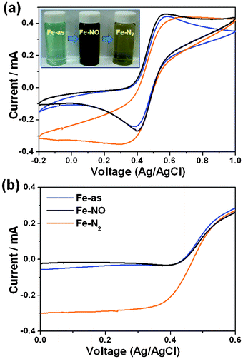
The as-prepared Fe(II)SO4 (Fe-as, blue) is saturated with NO gas to absorb NO in the solution. At 30 °C, the Fe2+ in the NO-absorbed solution (Fe-NO, dark brown) is oxidized into Fe3+. After the complete oxidation of Fe2+ (eqn (5)), the solution containing Fe3+ (Fe-N2) becomes yellow from dark brown. At relatively low temperature, the nitrogen oxide can oxidize Fe2+ into Fe3+ simultaneously reducing NO into N2 because nitrogen oxide is a strong oxidant. Fig. 1(a) shows cyclic voltammograms of Fe-as, Fe-NO, and Fe-N2 using catalyst-coated glassy carbon, Ag/AgCl, and Pt wire as a working, reference, and counter electrodes, respectively. The oxidation peaks at ∼0.5 V in Fe-as and Fe-NO solutions correspond to oxidation of Fe2+ to Fe3+, whereas the reduction peaks at ∼0.4 V correspond to reduction of Fe3+ into Fe2+. Furthermore, the oxidation peak at ∼0.5 V in Fe-N2 solution corresponds to oxidation of Fe2+ into Fe3+. However, Fe-N2 solution exhibits a limiting reduction current density at ∼0.4 V. To further characterize reduction properties of Fe-as, Fe-NO, and Fe-N2 solution, linear sweep voltammetric curves were obtained using a catalyst-coated rotating disc electrode as indicated in Fig. 1(b). The limiting reduction current densities of Fe3+ to Fe2+ in Fe-N2 is much higher than those in Fe-as and Fe-NO. The high limiting current density in Fe-N2 may be mainly due to the saturated concentration of Fe3+ produced by completely reducing NO into N2.6
 |
| | Fig. 1 Electrochemical reduction reactions of N-doped carbon catalysts in Fe-as, Fe-NO, and Fe-N2. (a) Cyclic and (b) linear sweep voltammograms for Fe(III) reduction on the catalysts. | |
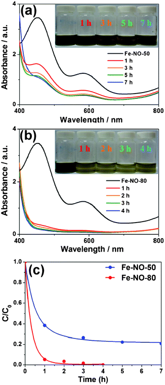
As already shown in the Fig. 1, the Fe-NO solution kept at 30 °C for 24 h was completely transformed into the Fe-N2. Fig. 2 shows absorbance intensities of the Fe-NO solutions maintained at 50 and 80 °C (referred to as Fe-NO-50 and Fe-NO-80, respectively) as a function of time. The absorbance spectra intensities of Fe-NO-50 after 1, 3, 5, and 7 h gradually decrease (Fig. 2(a)). As indicated in the inset of the Fig. 2(a), the color of Fe-NO-50 is changed from dark brown to yellow by oxidizing Fe2+ into Fe3+ with complete reduction of NO into N2. Furthermore, the absorbance intensities of Fe-NO-80 after 1, 2, 3, and 4 h abruptly decrease (Fig. 2(b)). With increasing duration, Fe-NO-80 turns yellow from dark brown by simultaneously oxidizing Fe2+ into Fe3+ with transformation of NO into N2, as indicated in the inset of Fig. 2(b).7Fig. 2(c) shows the reduction rate of NO with oxidize Fe2+ into Fe3+ at 50 and 80 °C. At relatively high temperature of 80 °C, Fe2+ can be oxidized into Fe3+ with almost complete NO conversion in the range of 95–100%. Especially, the NO in the Fe-NO-80 after 4 h is mainly converted into N2(98.43%) with a slight amount of N2O(1.57%). However, the residual N2O during the reduction of NO could be a serious limitation because of its very high global warming potential and ozone depleting potential. As shown in Fig. S1, ESI,† it is found that the Fe2+ in the N2O-bubbled solution can be oxidized into Fe3+ by forming N2. After the oxidation of Fe2+ (eqn (9)), the solution containing Fe3+ becomes yellow representing transformation of N2O into N2.
| | | N2O reduction : 2Fe2+(aq) + N2O(g) + 2H+(aq) ↔ 2Fe3+(aq) + N2(g) + H2O | (9) |
 |
| | Fig. 2 UV-Vis absorbance spectra of the Fe-NO solutions maintained at 50 and 80 °C as a function of time. UV-Vis absorbance spectra of (a) Fe-NO-50 and (b) Fe-NO-80. (c) Comparison of NO concentration in Fe-NO-50 and Fe-NO-80. | |
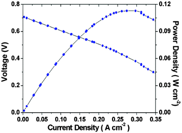
Fig. 3 shows characteristic curves of a H2–Fe3+ fuel cell measured at 70 °C using Pt/C and N-doped carbon as anode and cathode catalyst, respectively.8 The H2 gas humidified at 70 °C was supplied at anode with a flow rate of 27.8 mL min−1 and Fe-NO-80 after 4 h was flowed with a flow rate of 2.0 mL min−1 at cathode without backpressure regulators of the cell. In the polarization curves at 70 °C, open circuit voltage and maximum power density are 0.71 V and 110 mW cm−2, respectively. The H2–Fe3+ electrochemical cell exhibits an improved activation polarization representing highly efficient catalytic activity for the reduction of Fe3+ to Fe2+ at the cathode. At 0.3 A cm−2, the percentage of conversion from Fe(III) to Fe(II) is about 37.3%. However, to systematically characterize H2–Fe3+ electrochemical cell, the effect of concentration and flow rate on the cell performance will be considered in further work.
 |
| | Fig. 3 Polarization curves of H2–Fe3+ fuel cell at 70 °C with H2 supplied at anode and Fe-NO-80 flowed at cathode. | |
The chemical reduction of a contamination source such as NO by oxidizing Fe2+ into Fe3+ may be also utilized in the reduction of Cl2 as in the following equation:
| | | 2Fe2+ + Cl2 ↔ 2Fe3+ + 2Cl− | (10) |
The Fe
2+ in the Cl
2-absorbed solution (Fe–Cl
2) is oxidized into Fe
3+ by forming HCl. After the complete oxidation of Fe
2+ (
eqn (10)), the solution (Fe–HCl) containing Fe
3+ becomes brown yellow from blue. The oxidation peaks at ∼0.90 V in Fe–Cl
2 and Fe–HCl solution correspond to oxidation of Fe
2+ to Fe
3+, whereas the reduction peaks at ∼0.05 V correspond to reduction of Fe
3+ to Fe
2+ (Fig. S2(a), ESI
†). The reduction current density of Fe
3+ to Fe
2+ in Fe–HCl is much higher than that in Fe–Cl
2 (Fig. S2(b), ESI
†), suggesting an excellent reduction reaction of Cl
2 into HCl by oxidizing Fe
2+ into Fe
3+.
In summary, we have demonstrated complete reduction reaction of NO into N2 by oxidizing Fe2+ contained in a NO-absorbed solution into Fe3+. To regenerate Fe2+ as an absorbent of NO from Fe3+, the electrochemical cell, supplied by H2 at anode and Fe3+-containing solution at cathode, has been combined producing electricity. The H2–Fe3+ electrochemical cell at 80 °C exhibited open circuit voltage of 0.71 V and maximum power density of 110 mW cm−2, representing highly efficient catalytic activity for the Fe3+ reduction reaction at the cathode.
Acknowledgements
This work was supported by the National Research Foundation of Korea Grant funded by the Korean Government (NRF-2011-0030335).
References
-
(a) C. Johnson, J. Henshaw and G. Mclnnes, Nature, 1992, 355, 69–72 CrossRef CAS;
(b) V. I. Pârvulescu, P. Grange and B. Delmon, Catal. Today, 1998, 46, 233–316 CrossRef;
(c) R. W. Allen, O. Amram, A. J. Wheeler and M. Brauer, Atmos. Environ., 2011, 45, 369–378 CrossRef CAS;
(d) M. A. Gómez-García, V. Pitchon and A. Kiennemann, Environ. Int., 2005, 31, 445–467 CrossRef.
-
(a) G. Carja, G. Delahay, C. Signorile and B. Coq, Chem. Commun., 2004, 1404–1405 RSC;
(b) P. Leung, A. Tsolakis, J. Rodríguez-Fernández and S. Golunski, Energy Environ. Sci., 2010, 3, 780–788 RSC;
(c) Gongshin Qi and T. Yang Ralph, Chem. Commun., 2003, 848–849 RSC;
(d) H. Jiang, L. Xing, O. Czuprat, H. Wang, S. Schirrmeister, T. Schiesteld and J. Caro, Chem. Commun., 2009, 6738–6740 RSC.
-
(a) Y. Shi, D. Littlejohn, P. B. Kettler and S.-G. Chang, Environ. Prog., 1996, 15, 153–158 CrossRef CAS;
(b) E. K. Pham and S.-G. Chang, Nature, 1994, 369, 139–141 CrossRef CAS;
(c) X.-H. Mi, L. Gao, S.-H. Zhang, L.-L. Cai and W. Li, Bioresour. Technol., 2009, 100, 2940–2944 CrossRef CAS;
(d) L. Gao, X.-H. Mi, Y. Zhou and W. Li, Bioresour. Technol., 2011, 102, 2605–2609 CrossRef CAS;
(e) S. Bosio, A. Ravella, G. B. Saracco and G. Genon, Ind. Eng. Chem. Process Des. Dev., 1985, 24, 149–152 CrossRef CAS;
(f) S. Uchlda, T. Kobayashl and S. Kageyama, Ind. Eng. Chem. Process Des. Dev., 1983, 22, 323–329 CrossRef.
-
(a) V. Blagojevic, M. J. Y. Jarvis, E. Flaim, G. K. Koyanagi, V. V. Lavrov and D. K. Bohme, Angew. Chem., Int. Ed., 2003, 42, 4923–4927 CrossRef CAS;
(b) N. Macleod, F. J. Williams, M. S. Tikhov and R. M. Lambert, Angew. Chem., Int. Ed., 2005, 44, 3730–3732 CrossRef CAS.
-
(a) S. H. Bergens, C. B. Gorman, G. Tayha, R. Plamore and G. M. Whitesides, Science, 1994, 265, 1418–1420 CAS;
(b) D. B. Weibel, R. Boulatov, A. Lee, R. Ferrigno and G. M. Whitesides, Angew. Chem., Int. Ed., 2005, 44, 5682–5686 CrossRef CAS;
(c) J. T. Kummer and D-G. Oei, J. Appl. Electrochem., 1985, 15, 619–629 CrossRef CAS.
-
(a) G. C. C. Yang and H.-L. Lee, Water Res., 2005, 39, 884–894 CrossRef CAS;
(b) K. B. Holt, D. J. Caruana and E. J. Millán-Barrios, J. Am. Chem. Soc., 2009, 131, 11272–11273 CrossRef CAS.
-
(a) Y. G. Zhang, H. S. Wang, G. Somesfalean, Z. Y. Wang, X. T. Lou, S. H. Wu, Z. G. Zhang and Y. K. Qin, Atmos. Environ., 2010, 44, 4266–4271 CrossRef CAS;
(b) M. Jaworska and Z. Stasicka, New J. Chem., 2005, 29, 604–612 RSC.
- S.-B. Han, Y.-J. Song, Y.-W. Lee, A-R. Ko, J.-K. Oh and K.-W. Park, Chem. Commun., 2011, 47, 3496–3498 RSC.
Footnote |
| † Electronic supplementary information (ESI) available. See DOI: 10.1039/c2ra21750c |
|
| This journal is © The Royal Society of Chemistry 2012 |
Click here to see how this site uses Cookies. View our privacy policy here. 


