DOI:
10.1039/C2RA21580B
(Paper)
RSC Adv., 2012,
2, 10550-10555
Preparation of a three-dimensional interpenetrating network of TiO2 nanowires for large-area flexible dye-sensitized solar cells
Received
26th July 2012
, Accepted 5th September 2012
First published on 6th September 2012
Abstract
Platinum (Pt) and single-wall carbon nanotubes (SWCNTs) were sprayed onto Titanium (Ti) mesh to form a Pt–SWCNT/Ti counter electrode using a vacuum thermal decomposition method at a low temperature. A three-dimensional interpenetrating network of TiO2 nanowires (3-D IPN TNWs) was successfully prepared on Ti foil through a facile hydrothermal approach. A TiO2 colloid was coated on the 3-D IPN TNWs to form a large-area flexible anode using a doctor-scraping technique. The influences of the concentration of NaOH on the growth of 3-D IPN TNWs and on the photovoltaic performances of dye-sensitized solar cells (DSSCs) were investigated. Under an optimized condition, the power conversion efficiency of a large-area (100 cm2) flexible DSSC reached 6.43%, with a short-circuit current density of 6.83 mA cm−2, an open circuit voltage of 0.724 V, and a fill factor of 0.715. Under irradiation with a natural light intensity of 55 mW cm−2 outdoors, the efficiency of power conversion was increased by 10.29% compared with the flexible DSSC without 3-D IPN TNWs.
Introduction
Dye-sensitized solar cells (DSSC), originally invented by O' Regan and Grätzel in 1991, are becoming a promising candidate to replace conventional silicon solar cells owing to their low associated cost, simple preparation procedure, eco-friendly characteristics, and respectable power conversion efficiency (>12%).1,2 In general, the DSSC consists of a dye-sensitized porous nanocrystalline TiO2 film electrode, a redox electrolyte, and a platinized counter electrode. In order to improve the photovoltaic performance of the TiO2 anode, many efforts have been devoted to the design and synthesis of TiO2 with particular structures, such as nanotubes,3–6 nanorods7 and nanowires.8–10 Especially, the nanowire is desirable for DSSCs, since it can provide direct pathways for the rapid collection of photogenerated electrons, which could improve the photovoltaic performance of the device.11 On the other hand, fabrication of TiO2 on flexible conductive substrates (such as metal foils and polymer substrates) has been investigated to realize a high-speed and low-cost manufacturing process of DSSC modules.5,12–14 Up-sizing of the DSSC module is another one of the important technologies to bring about commercialization of DSSCs. Cell size and conductivity of substrates influence the internal resistance of solar cells, which consequently affect the fill factor and conversion efficiency of them. Some reports about large size DSSCs were published.15–23
Ti foils and Ti meshes have relatively low sheet resistance and superior corrosion resistance in the contacting I−/I3− electrolyte, due to the passive oxide film of TiO2 on them. In this paper, by integrating the merits of Ti foils and Ti meshes, a facile, low-temperature vacuum thermal decomposition method is presented to prepare a high performance platinum and single-wall carbon nanotubes (Pt–SWCNT/Ti) counter electrode on the flexible Ti mesh. A three-dimensional interpenetrating network of TiO2 nanowires (3-D IPN TNWs) has been successfully prepared on the Ti foil through a simple hydrothermal approach, and a TiO2 colloid has been coated on the 3-D IPN TNWs to form a TiO2 anode for the large-area flexible DSSC.
Experiments
Materials
H2PtCl6·6H2O, ethanol, isopropanol, n-butanol iodine, iodine, lithium iodide, tetrabutyl ammonium iodide, 4-tert-butyl-pyridine, acetonitrile, tetrabutyl titanate, titanium tetrachloride, sodium hydroxide, hydrochloric acid, hydrofluoric acid, nitric acid, PEG-20000 and Triton X-100 are analysis purity grade, and they were purchased from Shanghai Chemical Agent Ltd. China. Single-wall carbon nanotubes (SWCNT, purity: 90% carbon nanotubes (CNTs), 90% SWCNTs, main range of external diameter <2 nm, length 2–5 μm, special surface area 500–700 m2 g−1) were purchased from Chengdo Organic Chemicals Co. Ltd., Chinese Academy of Sciences. Sensitized-dye N719 [cis-di(thiocyanato)-N,N′-bis(2,2′-bipyridyl-4-carboxylic acid-4-tetrabutylammonium carboxylate)ruthenium(II)] was purchased from Solaronix SA, Switzerland. The above agents were used without further purification.
Preparation of flexible Pt–SWCNT/Ti counter electrodes
A typical Pt–SWCNT/Ti counter electrode was prepared using the series of steps outlined below.24 The Ti mesh (0.05 mm thickness, purchased from Anheng Wire Mesh Co., Ltd. China) was cleaned with mild detergent and rinsed in distilled water, then immersed in hydrofluoric acid solution with a suitable concentration for 2 min and rinsed in distilled water again. A solution of H2PtCl6·6H2O was prepared by dissolution in isopropanol and n-butanol (volume ratio of 1![[thin space (1/6-em)]](https://www.rsc.org/images/entities/char_2009.gif) :1) at a concentration of 0.96 wt%. The SWCNTs were added to the H2PtCl6·6H2O solution at 0.12 wt%. The mixture was stirred for 6 h at room temperature and then sprayed onto both sides of the cleaned Ti mesh with the dimension of 21 cm × 5.5 cm. The Ti mesh was heated at 120 °C for 2 h in a vacuum drying oven (Suzhou Jiangdong Precision Instrument Co., Ltd., China), the Pt–SWCNT thus was deposited on the Ti mesh to form a Pt–SWCNT/Ti counter electrode. For comparison, a Pt/Ti counter electrode without SWCNTs was also prepared.
:1) at a concentration of 0.96 wt%. The SWCNTs were added to the H2PtCl6·6H2O solution at 0.12 wt%. The mixture was stirred for 6 h at room temperature and then sprayed onto both sides of the cleaned Ti mesh with the dimension of 21 cm × 5.5 cm. The Ti mesh was heated at 120 °C for 2 h in a vacuum drying oven (Suzhou Jiangdong Precision Instrument Co., Ltd., China), the Pt–SWCNT thus was deposited on the Ti mesh to form a Pt–SWCNT/Ti counter electrode. For comparison, a Pt/Ti counter electrode without SWCNTs was also prepared.
Fabrication of 3-D IPN TNWs films and flexible TiO2 anodes
In a typical preparation procedure,25 Ti foils (0.03 mm thickness, purchased from Baoji Yunjie Metal Production Co., Ltd. China) were cleaned using the same method as the Ti mesh above. The cleaned Ti foil was designated as sample A. The cleaned Ti foils were placed into three Teflon-lined autoclaves, respectively. The autoclaves were filled with 5 M NaOH solution (designated as sample B), 10 M NaOH solution (designated as sample C) and 15 M NaOH solution (designated as sample D) (packing volume < 80%) and sealed into a stainless tank, individually. Then the systems were heated at 140 °C for 2 h. After that, the autoclaves were naturally cooled to room temperature, the obtained samples were washed with distilled water carefully, and immersed in HCl aqueous solution (pH = 2) for 12 h, and then immersed in distilled water for several times until the pH value of the water equaled 7. The products were dried at 400 °C in air for 0.5 h. Thus, 3-D IPN TNWs films were obtained.
The TiO2 colloid (prepared according to our previous reports26,27) was coated on the samples A, B, C and D using a doctor-scraping technique. The thickness of the TiO2 film was controlled by the thickness of the adhesive tape around the edge of the substrate.26,27 After drying at room temperature, the TiO2 thin films were sintered at 450 °C for 30 min in air to produce nanocrystalline TiO2 films, the TiO2 anodes were immersed in a 0.05 M TiCl4 solution at 70 °C for 30 min, and then washed three times with distilled water. The treated TiO2 films were sintered at 400 °C for 20 min. When the TiO2 anodes were cooled to 80 °C, the obtained TiO2/Ti anodes were treated by ultraviolet–O2 at room temperature for 30 min. The flexible TiO2/Ti anodes were immersed in a 2.50 × 10⁻⁴ M solution of dye N719 in absolute ethanol for 24 h. This allowed sufficient time for the TiO2 films to absorb the dye adequately. Thus, flexible dye-sensitized TiO2/Ti anodes were obtained.
Assemblage of flexible DSSCs
Fig. 1 shows the diagrammatic drawing of the flexible DSSC. The flexible DSSC was assembled by injection of a redox-active electrolyte into the aperture between the TiO2/Ti anode and the Pt–SWCNT/Ti counter electrode. The two electrodes were clipped together with two transparent flexible plastics and a cyanoacrylate adhesive was used as a sealant to prevent the electrolyte solution from leaking. Epoxy resin was used for further sealing the cell to measure the stability of the cell. The redox electrolyte was injected, which consisted 0.60 M tetrabutyl ammonium iodide, 0.10 M LiI, 0.10 M I2, and 0.50 M 4-tert-butyl-pyridine in acetonitrile.
 |
| | Fig. 1 Diagrammatic drawing of a flexible DSSC. | |
Characterization
The surface features of samples were observed with a scanning electron microscope (SEM) (S-4800N, Hitachi, Japan). The samples for SEM were prepared by spray gold processing (E-1010, Ion Sputter, Hitachi, Japan), the compositions of samples were analyzed by an energy-dispersive X-ray spectrometer (EDS) attached to the SEM. The phase identification of the samples at different preparation stages was conducted with powder X-ray diffraction (XRD) (D8-advance, Bruker, Germany). The cyclic voltammetry (CV) profiles of the Pt/Ti and Pt–SWCNT/Ti counter electrodes were measured in a three-electrode electro-chemical cell with an electrochemical workstation (CHI660D, Shanghai Chenhua Device Company, China) using Pt/Ti and Pt–SWCNT/Ti as the working electrodes respectively, a Pt-foil as the counter electrode and an Ag/AgCl cell as the reference electrode dipped in an acetonitrile solution of 10 mM LiI, 1.0 mM I2 and 0.10 M LiClO4. The CV measurements were performed using a CHI660D electrochemical measurement system (scan condition: 100 mV s−1). The reflectivity of the flexible TiO2 anode was carried out with an ultraviolet-visible spectrophotometer (UV-2550, Shimadzu, Japan). The dye adsorbed on the electrode was determined by measuring the dye amount released in the solution of 5 ml 0.05 M NaOH. The measurement was carried out with an ultraviolet-visible spectrometer (UV-2401PC, Shimadzu, Japan).
Photoelectric measurements
The photovoltaic performance test of the flexible DSSC was conducted by measuring the I–V character curves using a CHI660D electrochemical measurement system under irradiation with natural light intensity (measured by Radiometer FZ-A, Photoelectric Inst. of Beijing Normal Univ., China) of 55 mW cm−2 outdoors. The photovoltaic performance [i.e., fill factor (FF) and overall energy conversion efficiency (η)] of the DSSC was calculated using the following equations:28| |  | (1) |
| |  | (2) |
, where ISC is short-circuit current (A), VOC is the open-circuit voltage (V), Pin is incident light power (W), and Imax (A) and Vmax (V) are the current and voltage in the I–V curves, respectively, at the point of maximum power output.
Results and discussion
Morphology and electrochemical properties of the Pt–SWCNT/Ti counter electrode
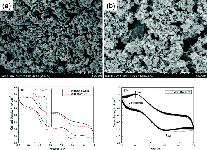
Fig. 2(a) and (b) show the SEM images of the Pt/Ti and Pt–SWCNT/Ti counter electrodes. It is obvious that Pt particles with a size diameter of about 250–500 nm have been produced on Ti meshes,24 and Fig. 2(b) shows the Pt particles are well connected by the SWCNTs. Fig. 2(c) shows CVs for the Pt/Ti and Pt–SWCNT/Ti counter electrodes (the CV data based on the second cycle). Both the two counter electrodes show two pairs of oxidation and reduction peaks, the oxidation and reduction pair on the right results from the redox reaction of 3I2 + 2e− → 2I3−, which directly affects the DSSC performance; while that on the left is attributed to the redox reaction of I3− + 2e− → 3I−, which has little effect on the DSSC performance.29–31 The peak currents and peak-to-peak separation (Epp), which are negatively correlated with the standard electrochemical rate constant of a redox reaction, are two important parameters for comparing catalytic activities of different CEs.32 The Pt–SWCNT/Ti counter electrode shows larger oxidation and reduction current density suggesting that the Pt–SWCNT/Ti counter electrode as an electrocatalyst counter electrode is more efficient than the Pt/Ti counter electrode in DSSCs.24 Furthermore, the Pt–SWCNT/Ti counter electrode has lower Epp (E2pp = 0.272 mV) than that of the Pt/Ti counter electrode (E1pp = 0.404 mV), implying the Pt–SWCNT/Ti counter electrode is superior to the Pt/Ti counter electrode, which can be attributed to its high electrocatalytic activity from Pt particles and large surface area and superior electrical conductivity from the SWCNT. Fig. 2(d) shows that 400 successive CV cycles of the Pt–SWCNT/Ti counter electrode have little change, which indicates that the Pt–SWCNT/Ti counter electrode has good chemical stability and is tightly bound to the Ti foil surface.33 Therefore, we assembled the large-area flexible DSSC using the Pt–SWCNT/Ti as the counter electrode in this paper.
 |
| | Fig. 2 SEM images of (a) Pt/Ti and (b) Pt–SWCNT/Ti counter electrodes, (c) CVs for Pt/Ti electrodes with and without SWCNTs, (d) a total of 400 consecutive CVs for the I2/I− system using the Pt–SWCNT/Ti counter electrode, all the CV data were measured at a scan rate of 100 mV s−1. | |
Morphology and composition of the 3-D IPN TNWs
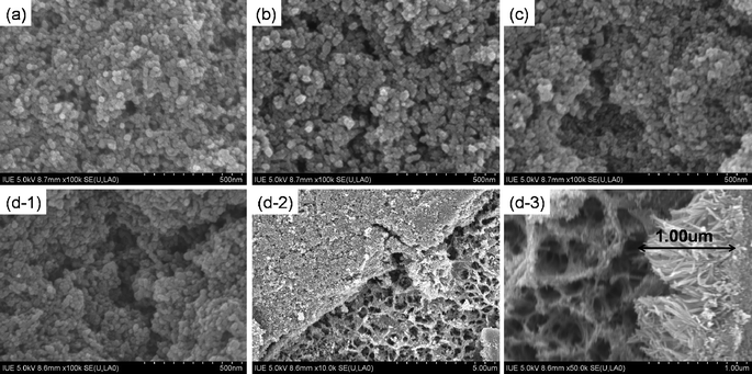
Fig. 3(a) shows the SEM image of the sample A. It is obvious that the surface of the cleaned Ti foil is roughened after being immersed in the hydrofluoric acid solution. As shown in the Fig. 3(b), the sample B was made of short stubby TNWs, these TNWs were heaping up on the Ti foil with a low void space. With the increase of the NaOH concentration, the generated TNWs become more slender, resulting in a higher void space. Fig. 3(d) shows the SEM image of the sample D, which was fabricated in 15 M NaOH solution. It is obvious that 3-D IPN TNWs with a size diameter of about 10–100 nm and the thickness of about 0.5–1.0 μm (Fig. 5(d-3)) have been produced on the Ti foil.
 |
| | Fig. 3 SEM images of samples A (a), B (b), C (c) and D (d). | |
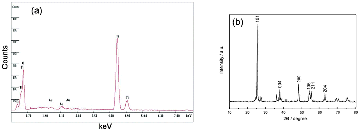
The EDS (Fig. 4(a)) spectrum shows that the sample D consists of Au, Ti, O, and no Na element. However, Au which came from the spray gold processing, and Na were washed by the distilled water and HCl aqueous solution. Therefore, the 3-D IPN TNWs consist of Ti and O. Fig. 4(b) demonstrates the XRD pattern of the sample D. The characteristic diffraction peak at 2θ of 25.3° for the titania anatase (101) crystal face is observed, and all sharp peaks can be indexed as titania anatase, which is in accordance with the EDS.
Influence of different 3-D IPN TNWs on the morphology of flexible TiO2 anodes
Fig. 5 shows the SEM images of the flexible TiO2 anodes prepared on the cleaned Ti foil and on the different 3-D IPN TNWs. It can be found that a TiO2 nanoparticles film was prepared on the 3-D IPN TNWs (Fig. 5(d-2)), and the 3-D IPN TNWs enhanced the connectivity among the TiO2 particles, TNWs and Ti substrate, which will result in quick and efficient transport for electrons in the film, and the enhancement of photocurrent.11 Compared to the flexible TiO2 anodes prepared on the samples A, B and C, the anode prepared on the sample D has the largest void space to harvest the most light.
 |
| | Fig. 5 SEM images of flexible TiO2 anodes on the samples A (a), B (b), C (c) and D (d-1, d-2, and d-3). | |
Influence of different 3-D IPN TNWs on the reflectivity and dye adsorption of flexible TiO2 anodes
Fig. 6 shows the reflectance and dye absorption spectra of the flexible dye-sensitized TiO2 anodes prepared on the cleaned Ti foil and on the different 3-D IPN TNWs, where the different 3-D IPN TNWs are corresponding to the samples B, C and D, respectively. From Fig. 6(A), the wavelength at 530 nm comes from the dye absorption,34 the reflectance of the sample A is the highest, the lower ones are the samples B and C, and the smallest one is the sample D. One possible explanation is the surface of the cleaned Ti foil is flat with little rough areas, and this structure leads to the highest reflectance. The sample D with a special surface of a 3-D IPN structure could be used to catch the light, resulting in the smallest reflectance. The lower reflectance means that less light is reflected off the space and more light is utilized. Another reason may be due to the dye adsorption of the TiO2 anodes. In Fig. 6(B), the absorption peaks at 370 nm and 500 nm come from the dye absorption and blue-shift in the alkali solution,34 the absorbance for the sample D is the highest, which results in the most adsorption for the dye. According to the Lambert–Beer's law, higher absorbance means higher dye concentration. It is well known that the photocurrent of the flexible DSSC is directly correlated with the amount of the dye molecule, the more dye molecules are adsorbed, the more incident light is harvested, and the larger photocurrent occurs. According to our experiments, the flexible TiO2 anode prepared on the sample D can harvest the most light and produce the largest photocurrent.
 |
| | Fig. 6 Reflectance (A) and dye adsorption (B) of the dye-sensitized TiO2 anodes on the samples A, B, C and D. | |
Photovoltaic characterization of flexible DSSCs
The photovoltaic performances of large-area (100 cm2) flexible DSSCs prepared on the cleaned Ti foil and on the different 3-D IPN TNWs were measured under irradiation with a natural light intensity of 55 mW cm−2 outdoors, which were reproduced many times without obvious change, and the results were summarized in Table 1. It can be seen that the ISC value increases from top to bottom. On the one hand, the reflectance reduces from A to D, which directly influences the photocurrent. On the other hand, the 3-D IPN surface structure can enhance the scattering effect to increase the absorption and utilization of light, resulting in the higher ISC.35 However, the VOC and FF attached to the samples B, C and D have similar values of about 0.724 V and 0.714 V, which are higher than that of the sample A. This is due to the direct pathways for the rapid collection of photogenerated electrons, which could improve the photovoltaic performance of the device.11 In our experiments, the large-area (100 cm2) flexible DSSC based on the sample D produced the largest photocurrent of 0.683 A, and the highest energy conversion efficiency of 6.43%.
Table 1 The photovoltaic performance of DSSCs with different samples
| Samples |
I
SC (A) |
J
SC (mA cm−2) |
V
OC (V) |
FF
|
η (%) |
| A |
0.636 |
6.36 |
0.717 |
0.703 |
5.83 |
| B |
0.662 |
6.62 |
0.723 |
0.714 |
6.21 |
| C |
0.676 |
6.76 |
0.725 |
0.713 |
6.35 |
| D |
0.683 |
6.83 |
0.724 |
0.715 |
6.43 |
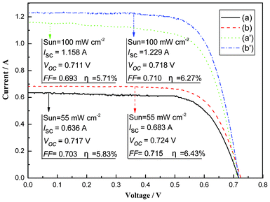
Based on the optimal conditions of the TiO2 anode preparation, the flexible DSSCs were assembled using the samples A and D. The photocurrent–voltage curves (Fig. 7) of the flexible DSSCs were measured under irradiation with a natural light intensity of 55 mW cm−2 outdoors and with a simulated solar light of 100 mW cm−2 from a 500 W xenon arc lamp (XQ-500W, Shanghai Photoelectricity Device Company, China) in a laboratory setting. Under the test system outdoors, the DSSC using the sample A had an ISC of 0.636 A, VOC of 0.717 V, FF of 0.703, and η of 5.83%, whereas the DSSC using the sample D achieved an ISC of 0.683 A, VOC of 0.724 V, FF of 0.715, and η of 6.43%. The light-to-electric energy conversion efficiency for the flexible DSSC using the sample D is increased by 10.29% compared to the flexible DSSC using the sample A. However, the photovoltaic performances for the both the two samples were reduced under the test system in the laboratory setting. One possible explanation is the spectral mismatch between natural and simulated solar light. This could be given more attention in future studies. To sum up, the large area flexible DSSC based on the 3-D IPN TNWs achieved more than 6.2% efficiency, which should accelerate the practical application of flexible DSSCs.
 |
| | Fig. 7 The photocurrent–voltage curves of flexible DSSCs based on samples A and D. | |
Conclusion
In summary, a Pt–SWCNT/Ti counter electrode has been fabricated on a Ti mesh using a vacuum thermal decomposition method at low temperature, and the Pt–SWCNT/Ti counter electrode as an electrocatalyst counter electrode is more efficient than that of the Pt/Ti counter electrode in DSSCs. 3-D IPN TNWs have been successfully prepared on the Ti foil in 15 M NaOH solution at 140 °C for 2 h. The TiO2 anode based on the 3-D IPN TNWs has low reflectance, which could harvest a great amount of light and produce a large photocurrent. Under optimized conditions, the power conversion efficiency of the large-area (100 cm2) flexible DSSC reaches 6.43% under irradiation with a natural light intensity of 55 mW cm−2 measured outdoors, with a short-circuit current density of 6.83 mA cm−2, an open circuit voltage of 0.724 V, and a fill factor of 0.715. The efficiency is increased by 10.29% compared to the flexible DSSC without 3-D IPN TNWs.
Acknowledgements
This work was supported by the National High Technology Research and Development Program of China (No. 2009AA03Z217) and the National Natural Science Foundation of China (No. 90922028, 51002053).
References
- B. O' Regan and M. Grätzel, Nature, 1991, 353, 737–740 CrossRef CAS.
- M. Grätzel, Acc. Chem. Res., 2009, 42, 1788–1798 CrossRef.
- T. Kasuga, M. Hiramatsu, A. Hoson, T. Sekino and K. Niihara, Langmuir, 1998, 14, 3160–3163 CrossRef CAS.
- Z. R. Tian, J. A. Voigt, J. Liu, B. Mckenzie and H. F. Xu, J. Am. Chem. Soc., 2003, 125, 12384–12385 CrossRef CAS.
- Y. M. Xiao, J. H. Wu, G. T. Yue, G. X. Xie, J. M. Lin and M. L. Huang, Electrochim. Acta, 2010, 55, 4573–4578 CrossRef CAS.
- J. Q. Luo, L. Gao, J. Sun and Y. Q. Liu, RSC Adv., 2012, 2, 1884–1889 RSC.
- B. Liu and E. S. Aydil, J. Am. Chem. Soc., 2009, 131, 3985–3990 CrossRef CAS.
- Z. Miao, D. S. Xu, J. H. Ouyang, G. L. Guo, X. S. Zhao and Y. Q. Tang, Nano Lett., 2002, 2, 717–720 CrossRef CAS.
- B. Tan and Y. Y. Wu, J. Phys. Chem. B, 2006, 110, 15932–15938 CrossRef CAS.
- X. J. Feng, K. Shankar, M. Paulose and C. A. Grimes, Angew. Chem., 2009, 121, 8239–8242 CrossRef.
- X. Zhang, B. Yao, L. Zhao, C. Liang, L. Zhang and Y. Mao, J. Electrochem. Soc., 2001, 148, G398–G400 CrossRef CAS.
- S. Ito, N. C. Ha, G. Rothenberger, P. Liska, P. Comte, S. M. Zakeeruddin, P. Péchy, M. K. Nazeeruddin and M. Grätzel, Chem. Commun., 2006, 4004–4006 RSC.
- V. Vijayakumar, A. D. Pasquier and D. P. Birnie III., Sol. Energy Mater. Sol. Cells, 2011, 95, 2120–2125 CrossRef CAS.
- Z. S. Xue, W. Zhang, X. Yin, Y. M. Cheng, L. Wang and B. Liu, RSC Adv., 2012, 2, 7074 RSC.
- M. Biancardo, K. West and F. C. Krebs, Sol. Energy Mater. Sol. Cells, 2006, 90, 2575–2588 CrossRef CAS.
- G. R. A. Kumara, S. Kaneko, A. Konno, M. Okuya, K. Murakami, B. Onwona-agyeman and K. Tennakone, Progr. Photovolt.: Res. Appl., 2006, 14, 643–651 CrossRef CAS.
- E. Ramasamy, W. J. Lee, D. Y. Lee and J. S. Song, J. Power Sources, 2007, 165, 446–449 CrossRef CAS.
- C. Lungenschmied, G. Dennler, H. Neugebauer, S. N. Sariciftci, M. Glatthaar, T. Meyer and A. Meyer, Sol. Energy Mater. Sol. Cells, 2007, 91, 379–384 CrossRef CAS.
- L. H. Hu, S.Y. Dai, J. Weng, S. F. Xiao, Y. F. Sui, Y. Huang, S. H. Chen, F. T. Kong, X. Pan, L. Y. Liang and K. J. Wang, J. Phys. Chem. B, 2007, 111, 358–362 CrossRef CAS.
- W. J. Lee, E. Ramasamy, D. Y. Lee and J. S. Song, J. Photochem. Photobiol., A, 2008, 194, 27–30 CrossRef CAS.
- D. H. Yeon, K. K. Kim, N. G. Park and Y. S. Cho, J. Am. Ceram. Soc., 2010, 93, 1554–1556 CAS.
- Y. M. Xiao, J. H. Wu, G. T. Yue, J. M. Lin, M. L. Huang, L. Q. Fan and Z. Lan, Electrochim. Acta, 2011, 58, 621–627 CrossRef CAS.
- J. H. Wu, Y. M. Xiao, G. T. Yue, Q. W. Tang, J. M. Lin, M. L. Huang, Y. F. Huang, L. Q. Fan, Z. Lan, S. Yin and T. Sato, Adv. Mater., 2012, 24, 1884–1888 CrossRef CAS.
- Y. M. Xiao, J. H. Wu, G. T. Yue, J. M. Lin, M. L. Huang and Z. Lan, Electrochim. Acta, 2011, 56, 8545–8550 CrossRef CAS.
- W. L. Wang, H. Lin, J. B. Li and N. Wang, J. Am. Ceram. Soc., 2008, 91, 628–631 CrossRef CAS.
- J. H. Wu, Z. Lan, J. M. Lin, M. L. Huang, S. C. Hao, T. Sato and S. Yin, Adv. Mater., 2007, 19, 4006–4011 CrossRef CAS.
- J. H. Wu, S. C. Hao, Z. Lan, J. M. Lin, M. L. Huang, Y. F. Huang, P. J. Li, S. Yin and T. Sato, J. Am. Chem. Soc., 2008, 130, 11568–11569 CrossRef CAS.
- M. Grätzel, Progr. Photovolt.: Res. Appl., 2000, 8, 171–185 CrossRef.
- L. M. Peter and K. G. U. Wijayantha, Electrochim. Acta, 2000, 45, 4543–4551 CrossRef CAS.
- N. Kopidakis, K. D. Benkstein, J. Lagemaat and A. J. Frank, J. Phys. Chem. B, 2003, 107, 11307–11315 CrossRef CAS.
- A. N. M. Green, R. E. Chandler, S.A. Haque, J. Nelson and J. R. Durrant, J. Phys. Chem. B, 2005, 109, 142–150 CrossRef CAS.
- J. Roy-Mayhew, D. Bozym, C. Punckt and I. Aksay, ACS Nano, 2010, 4, 6203–6211 CrossRef CAS.
- H. Guo, Y. Li, L. Fan, X. Wu and M. Guo, Electrochim. Acta, 2006, 51, 6230–6237 CrossRef CAS.
- M. K. Nazeeruddin, F. De Angelis, S. Fantacci, A. Selloni, G. Viscardi, P. Liska, S. Ito, B. Takeru and M. Grätzel, J. Am. Chem. Soc., 2005, 127, 16835–16847 CrossRef CAS.
- S. Ito, S. Yoshida and T. Watanabe, Chem. Lett., 2000, 29, 70–71 CrossRef.
|
| This journal is © The Royal Society of Chemistry 2012 |
Click here to see how this site uses Cookies. View our privacy policy here.