A versatile method for enhancement of electromechanical sensitivity of silicone elastomers
Sebastian
Risse
*a,
Björn
Kussmaul
b,
Hartmut
Krüger
b and
Guggi
Kofod
a
aUniversity of Potsdam, Institute of Physics and Astronomy, Karl-Liebknecht-Str. 24/25, 14476 Potsdam, Germany. E-mail: Sebastian.Risse@uni-potsdam.de
bFraunhofer Institute for Applied Polymer Research, Geiselbergstr. 69, 14476 Potsdam, Germany
First published on 2nd August 2012
Abstract
Dielectric elastomer actuators (DEAs) draw their function from their dielectric and mechanical properties. The paper describes the fabrication and various properties of molecularly grafted silicone elastomer films. This was achieved by addition of high-dipole molecular co-substituents to off-the-shelf silicone elastomer kits, Elastosil RT 625 and Sylgard 184 by Wacker and Dow Corning, respectively. Strong push–pull dipoles were chemically grafted to both polymer networks during a one step film formation process. All manufactured films were characterized using 13C-NMR and FT-IR spectroscopy, confirming a successful attachment of the dipoles to the silicone network. Differential scanning calorimetry (DSC) results showed that grafted dipoles were distributed homogeneously throughout the material avoiding the formation of nano-scale aggregates. The permittivity increased with the amount of dipole at all frequencies, while the Young's modulus and electrical breakdown strength were reduced. Actuation strain measurements in the pure shear configuration independently confirmed the increase in electromechanical sensitivity. The ability to enhance electromechanical properties of off-the-shelf materials could strongly expand the range of actuator properties available to researchers and end-users.
Introduction
The rapid progress in humanoid robotics strongly depends upon the availability of powerful, compact and flexible actuators.1,2 Although these applications are fully operational, they typically require a tendon from a low energy density actuator placed externally for actuation. The availability of compact, high energy density actuators could enable a deeper integration in active biomimetic architectures. This may be possible through novel actuation principles and improvement in the corresponding materials. One promising actuation principle is exploited in DEAs,3 which operates by stretching when charged with electrical energy. The permittivity enhancement of the dielectric elastomer leads to improvements as necessary for compact and flexible actuators,4–9 and could also lead to improvements when the same materials are used for energy harvesting from ocean waves.10 It was shown that the permittivity of elastic composite films can be enhanced with conductive11–13 and non-conductive14–17 particles. For all, a major problem was posed by the inhomogeneous distribution of the filler material due to sedimentation and phase separation effects.The authors recently showed that molecules with a high dipole moment may be grafted to a common polydimethylsiloxane (PDMS) elastomer network system,18 that consists of mainly three components: 1) long and elastic polymer chains and 2) strong, organic dipoles with vinyl end groups which form covalent bonds with the 3) cross-linking molecules. The film formation happens in a single step, in which the components are mixed and directly cast from the mixture. This creates an elastic rubber network with homogeneously distributed and covalently bound dipoles (Fig. 1), observed to enhance the permittivity of the material and its electromechanical response.18 However, up to now it is unknown whether this approach may be used with generally available off-the-shelf silicone elastomers. If this were possible, the technological developments invested in such systems regarding durability, weathering, network reinforcements, rheological properties, etc., could potentially be combined with permittivity enhancement towards use in DEAs. This requires that the basic silicone network chemistry can be co-opted, and that interfering chemical pathways can be avoided.
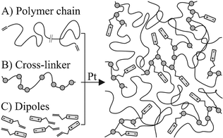 | ||
| Fig. 1 Three initial substances (left) form, in a Pt-catalyzed hydrosilylation reaction, a rubber network (right). The one step film formation process leads to an homogeneous distribution of dipoles in the network. | ||
Here, the one step film formation is attempted with two off-the-shelf silicone elastomer kits (Elastosil RT 625 by Wacker and Sylgard 184 by Dow Corning), which form rubber networks in a Pt-catalyzed reaction (Fig. 1).
Molecules with high dipole moments are attached to the network using the Pt-catalyzed reaction pathway. The dipole molecule (Fig. 2) is functionalized with a vinyl end group and linked to the cross-linker molecule just as the end groups of the PDMS chain. Using the same pathway is expected to enhance the homogeneous distribution of the dipole molecule in the elastomer material.
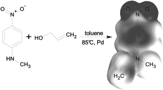 | ||
| Fig. 2 Synthetic pathway of N-allyl-N-methyl-p-nitroaniline. The electron density was calculated with the Hartree–Fock method in unexcited state in vacuum. Black and white corresponds to negative and positive charges, respectively. |μ| = 8.27 D, Mw = 192.2 g mol−1. | ||
The cross-linking process was monitored by FT-IR spectroscopy. The homogeneity of the distribution of dipoles and their covalent binding was investigated with DSC and 13C-NMR spectroscopy, respectively. Finally, the physical properties were examined with tensile testing, dielectric relaxation spectroscopy, electrical breakdown and actuation experiments.
Experimental
The dipole N-allyl-N-methylaniline (Fig. 2) was synthesized via a palladium catalyzed direct allylation of the corresponding aniline19 in yields above 95%. The vinyl-functionalization permits grafting to cross-linker molecules of the silicone network. The investigated silicone elastomer systems, Sylgard 184 by Dow Corning and Elastosil RT 625 by Wacker Silicones, are off-the-shelf, two-component silicone elastomer kits and were purchased from Kahmann & Ellerbrock GmbH & Co. KG. The two kits employ a Pt-catalyst as indicated by their respective data sheets. This substantiates the assumption of a typical Pt-catalysed hydrosilylation reaction. The components of both kits dissolve well in chloroform and were processed as follows.The film manufacturing process was facilitated by premixing three stock solutions, which were combined in the given volume ratios (Table 1). Solutions A and B are required to form the network and solution C introduces the dipoles. The amounts of cross-linker and dipole in solution C were chosen so that the molar amounts of methylhydrosiloxane units and dipoles are the same. This strategy is aimed to ensure that all dipoles can be covalently bond. After mixing, the solution was drop cast on Teflon coated steel substrates, confined by metal frames, which were then covered with perforated metal plates for homogeneous evaporation of the chloroform. After the solvent evaporated over night, the films were heated to 120 °C for 30 min to complete the cross-linking reaction and drive out remaining solvent. The dipole content  was varied by adjusting the amount n of solution C, yielding dipole contents up to 10.7 wt%.
| Sylgard | |
|---|---|
| A | 2.47 g Sylgard-A, 25.4 mg Pt-cat., 7.5 g CHCl3 |
| B | 2.49 g Sylgard-B, 7.51 g CHCl3 |
| C | 416 mg HMS-301, 308 mg dipole, 9.28 g CHCl3 |
mixture ratio: A![[thin space (1/6-em)]](https://www.rsc.org/images/entities/char_2009.gif) : :![[thin space (1/6-em)]](https://www.rsc.org/images/entities/char_2009.gif) B B![[thin space (1/6-em)]](https://www.rsc.org/images/entities/char_2009.gif) : :![[thin space (1/6-em)]](https://www.rsc.org/images/entities/char_2009.gif) C = 5 C = 5![[thin space (1/6-em)]](https://www.rsc.org/images/entities/char_2009.gif) : :![[thin space (1/6-em)]](https://www.rsc.org/images/entities/char_2009.gif) 0.5 0.5![[thin space (1/6-em)]](https://www.rsc.org/images/entities/char_2009.gif) : :![[thin space (1/6-em)]](https://www.rsc.org/images/entities/char_2009.gif) n ml n ml |
|
| Elastosil | |
| A | 2.0 g Elastosil-A, 8.0 g CHCl3 |
| B | 1.81 g Elastosil-B, 184 mg Pt-cat., 8.01 g CHCl3 |
| C | 307 mg HMS-301, 227 mg dipole, 9.28 g CHCl3 |
mixture ratio: A![[thin space (1/6-em)]](https://www.rsc.org/images/entities/char_2009.gif) : :![[thin space (1/6-em)]](https://www.rsc.org/images/entities/char_2009.gif) B B![[thin space (1/6-em)]](https://www.rsc.org/images/entities/char_2009.gif) : :![[thin space (1/6-em)]](https://www.rsc.org/images/entities/char_2009.gif) C = 4.5 C = 4.5![[thin space (1/6-em)]](https://www.rsc.org/images/entities/char_2009.gif) : :![[thin space (1/6-em)]](https://www.rsc.org/images/entities/char_2009.gif) 0.5 0.5![[thin space (1/6-em)]](https://www.rsc.org/images/entities/char_2009.gif) : :![[thin space (1/6-em)]](https://www.rsc.org/images/entities/char_2009.gif) n ml n ml |
|
The progress of the cross-linking reaction was determined using FT-IR spectroscopy, by observing the evolution of the C![[double bond, length as m-dash]](https://www.rsc.org/images/entities/char_e001.gif) C stretching band at 1600 cm−1. This measurement was performed with mixtures containing 10.7 wt% dipole. A total amount of 5 μl of mixed solution was placed in the spectrometer (Scimitar 2000 FT-IR, Varian Inc.) at room temperature and spectra (16 scans per spectrum) were recorded.
C stretching band at 1600 cm−1. This measurement was performed with mixtures containing 10.7 wt% dipole. A total amount of 5 μl of mixed solution was placed in the spectrometer (Scimitar 2000 FT-IR, Varian Inc.) at room temperature and spectra (16 scans per spectrum) were recorded.
Solid state 13C-NMR spectra were recorded (100.57 MHz, 1000 scans, Unity INOVA 400, Varian Inc.) for both elastomer systems with films containing 0.0 wt% and 10.7 wt% dipole, to investigate the completeness of the dipole grafting reaction.
Thermal properties were investigated with DSC (Diamond DSC, PerkinElmer). Several milligrams of films with 0.0 wt% and 10.7 wt% dipole content were cooled down to −150 °C (cooling rate 200 °C min−1) with liquid nitrogen. After a hold time of four minutes at −150 °C, the samples were heated to 80 °C with a heating rate of 20 °C min−1. The cycle ended by a cooling stage from 80 °C to −150 °C (cooling rate 20 °C min−1). The second heating and cooling curves were obtained by repetition of this cycle.
The mechanical characterization was performed with a standard tensile tester (Zwick-Roell, Z005). A laser cutting system (Versalaser, VL3.5) was used to cut out strips with 80 mm length and 10 mm width from the polymer films. Both ends of each strip were sealed with adhesive tape to improve the handling of the samples. Subsequently the strips were clamped between two gripping jaws of the tensile tester, located on opposite ends. A constant strain rate of 2.5% s−1 was applied and the resulting force was measured. With the prior determined thickness of the film, measured with a micrometer screw, the stress–strain curves were calculated. The Young's modulus Y was extracted from these curves by linear fitting for the first ten percent strain.
Electrical breakdown experiments were performed on elastomer disks with a diameter of 12 mm, cut from films with the laser cutting system. These disks were placed between two spherical metal electrodes (Ø = 6 mm). The bottom electrode was positioned in a block out of a PMMA table to ensure the planar alignment of the sample. The top electrode was fixed with a screw after contacting the surface of the silicone film with a small force. The electrical field between both electrodes was increased with a constant rate of 100 V s−1 until electrical failure. Thirty samples were measured for each combination of dipole and matrix material. The expectation value EB and the standard deviation of electrical breakdown strength were calculated with the Weibull statistic.20
The determination of the dielectric properties was performed with a dielectric relaxation spectrometer (Agilent, Alpha-Analyzer). Disks with a diameter of 26 mm were cut out from the elastomer film by using a laser cutting system. To ensure a reliable electric contact with the soft surface of the elastomer film and both metal electrodes (Ø = 20 mm), gold powder was applied with a cylindrical mask (Ø = 20 mm) to both sides of this film. The used voltage for this measurement was 1 V and frequency was ranged between 10−1 Hz to 105 Hz. The thickness of the film was determined with a micrometer screw. With the dielectric relaxation spectroscopy frequency dependent material parameters like relative permittivity ε′, dielectric loss ε′′ and electrical conductivity σ were obtained.
The electromechanical response of the films was investigated with actuators in pure shear configuration. Stiff PET frames were glued with a moisture curing silicone (E4 by Wacker) to the elastic films, so that a free standing rectangular area with the dimensions 80 mm × 10 mm was formed. Subsequently, the films were sprayed with a carbon black (Printex XE) silicone (Elastosil RT 625 by Wacker) mixture dissolved in toluene and hexane to obtain an electro-active region of 70 mm × 10 mm. This yields conductive and compliant electrodes on both sides. To ensure the electrical insulation between both electrodes, 5 mm of each side were covered with a PET mask during the spraying process. After clamping the sample in the tensile tester (Zwick-Roell, Z005) and contacting both electrodes to a high voltage source using adhesive aluminium tape, 10% pre-strain was applied to the pure shear actuator. After a relaxation time (≈1 h), the measurement was performed with a constant voltage rate of 5 V s−1 and a constant force, which was ensured by a closed loop program. The electromechanical response of the elastomer is extracted from the actuation strain curve sact(E), whose analytical expression for small strains can be derived as follows:
Hook's law (eqn (1)) connects the perpendicular strains si with their stresses σi (i = x, y, z) and can be applied for small deformations.
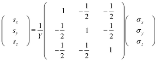 | (1) |
In pure shear configuration the strain in the width direction is zero (sy = 0). The stress in thickness direction σz is the Maxwell stress3σz = −ε′ε0E2. Based on eqn (1) the strains sx and sy can be expressed as follows:
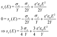 | (2) |
Rearranging of eqn (2) yields the effective actuation strain sact (eqn (3)).
 | (3) |
The term sps is the initial prestrain, which was set to 10% during the experiment. Note that the factor ¾ in the electromechanical sensitivity is a consequence of the pure shear configuration (sy = 0), while the factor in simple tension configuration21 (σy = 0) is ½. The electromechanical sensitivity β was determined in two different ways. Firstly by fitting the actuation curves to eqn (3) for strains up to 1% (βact) and, secondly, by calculation from results of dielectric and mechanical measurements (βmat).
Results and discussion
The targeted material property modification was investigated with several experiments. The evaluation of the time dependent absorbance of the C![[double bond, length as m-dash]](https://www.rsc.org/images/entities/char_e001.gif) C stretching band at 1600 cm−1 was achieved with FT-IR spectroscopy at room temperature. As can be seen in Fig. 3 both curves, Sylgard and Elastosil, show an increase in absorbance for times lower than 45 and 15 min, respectively. This is contributed to the increase in concentration during the evaporation of chloroform. The progress of the cross-linking reaction reduces the amount of vinyl groups and no further hydrosilylations can be observed after 4.5 h and 45 min for Sylgard and Elastosil, respectively. The Peaks between 13 and 16 h were originated by a subsequent heating step that completes the film formation process.
C stretching band at 1600 cm−1 was achieved with FT-IR spectroscopy at room temperature. As can be seen in Fig. 3 both curves, Sylgard and Elastosil, show an increase in absorbance for times lower than 45 and 15 min, respectively. This is contributed to the increase in concentration during the evaporation of chloroform. The progress of the cross-linking reaction reduces the amount of vinyl groups and no further hydrosilylations can be observed after 4.5 h and 45 min for Sylgard and Elastosil, respectively. The Peaks between 13 and 16 h were originated by a subsequent heating step that completes the film formation process.
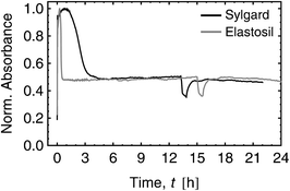 | ||
Fig. 3 FT-IR spectrum evaluation of Sylgard and Elastosil films for 10.7 wt% dipole content. Both curves show the time dependent normalized absorbance of the C![[double bond, length as m-dash]](https://www.rsc.org/images/entities/char_e001.gif) C stretching band at 1600 cm−1 during the cross-linking process. C stretching band at 1600 cm−1 during the cross-linking process. | ||
DSCs of both elastomers kits and the pure dipole as reference were performed to ensure a homogeneous distribution of the grafted dipoles avoiding the formation of nano-scale aggregates. The first heating DSC curve of the pure dipole in Fig. 4 shows a clear melting peak with its maximum at 40.5 °C. The inset illustrates the first derivative of the four curves with respect to temperature in the range of −80 to −68 °C. The maximum and minima for the second heating and both cooling curves, respectively, indicate a glass transition at ca. −71 °C. The first and second cooling curve show no crystallization peaks, indicating an amorphous solidification of the dipole. The second heating curve has two exothermic crystallization peaks at −32 °C and −3 °C followed by a melting peak at 37 °C. The process of crystallization in a formerly crystal-free amorphous phase is known as vitrification and can be observed by heating to a certain temperature or ageing. The latter can be seen after an ageing time of 24 h at room temperature for the third heating curve in Fig. 4. The progression of the third heating curve is similar to the first, indicating the presence of a crystalline phase.
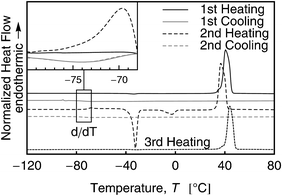 | ||
| Fig. 4 DSC curves of the pure dipole for three heating and two cooling curves. The inset illustrates the first derivative of the upper four curves with respect to the temperature T to ease the detection of the glass transition. The fifth curve (third heating) was obtained after an ageing time of 24 h at room temperature. | ||
The DSC curves in Fig. 5 show a glass transition at ca. −130 °C for Sylgard and Elastosil. No melting peak at around 40 °C can be observed for Sylgard and Elastosil, indicating that the dipole is well distributed in both elastomer matrices and does not form individual domains.
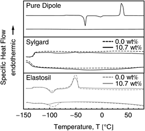 | ||
| Fig. 5 DSC curves for the pure dipole as well as for Sylgard and Elastosil films with 0 wt% and 10.7 wt% dipole content. The upper and lower curves in each graph represent the second heating and cooling, respectively. | ||
13C-NMR spectroscopy was performed (Fig. 6) to ensure that the dipole is not only well distributed but also covalently bound to the elastomer. The upper and lower curves in the Sylgard and Elastosil graphs of Fig. 6 show the NMR spectra for 0.0 wt% and 10.7 wt% dipole content, respectively. Each carbon atom peak and its area was numbered according to the molecular structure shown in the inset. Peaks 2, 3 and 4 relate to the dipole. Peaks 7 and 8 represent the amount of covalently bound dipole. Therefore, the ratio of peak areas 2, 3 and 4 to 7 and 8 indicate the relative amount of bound dipole. Peak areas 2 and 3 must be divided by a factor of two due to the symmetry of the phenyl ring, yielding conversion ratios rc as follows:
| rc(Sylgard) = 0.70 ± 0.25 |
| rc(Elastosil) = 0.92 ± 0.30 |
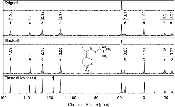 | ||
| Fig. 6 13C-NMR spectroscopy in the range from 10 to 160 ppm of Sylgard and Elastosil films with dipole contents of 0.0 wt% and 10.7 wt%. The intense peak of the methylsiloxane groups, located at 2 ppm, is not shown. The upper curves in the Elastosil and Sylgard graphs correspond to films with 0.0 wt% dipole content. The peaks are numbered with respect to the molecular structure of the bound dipole illustrated by the inset. The peak areas are listed above each peak. The bottom graph shows an Elastosil film with 10.7 wt% dipole content but only 10% Pt-catalyst used for the film formation. | ||
Remaining non-reacted dipoles would provide peaks at δ = 117 ppm and δ = 133 ppm indicated by two arrows in the bottom graph of Fig. 6. This is the case if only 10% Pt-catalyst of the original amount is used during the one step film formation process. In summary, the results of the 13C-NMR show a complete grafting of the dipole molecules to the silicone.
The stress–strain curves (Fig. 7) of the tensile testing experiment show that Sylgard and Elastosil are stiff and soft elastomers with low and high tear length, respectively. While the tear length of Sylgard remains almost constant for all dipole concentrations, the tear length of Elastosil films decreases with increasing dipole content.
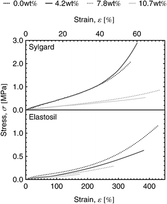 | ||
| Fig. 7 Stress–strain curves of Sylgard and Elastosil films for dipole contents ranging from 0.0 wt% to 10.7 wt%. | ||
The impact of the grafted dipoles on the dielectric properties of the elastomer films can be seen in the dielectric relaxation spectra (Fig. 8). The frequency dependent relative permittivity ε′ (top), dielectric loss ε′′ (middle) and electrical conductivity σ′ (bottom) are plotted in the frequency range from 100 mHz to 100 kHz for both elastomers. For clarity, only spectra of films with dipole contents of 0.0 wt%, 6.1 wt% and 10.7 wt% are shown. The dielectric constant increases for all frequencies with increasing dipole content as can be seen from relative permittivity spectra. The dielectric loss and the electrical conductivity increases by up to two orders of magnitude, which can be explained by the increasing hydrophilicity of the elastomer film due to the increasing amount of polar dipole molecules, leading to a higher water uptake.
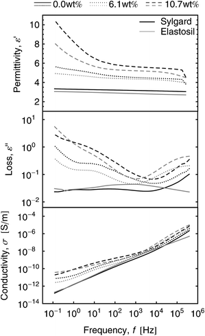 | ||
| Fig. 8 Relative permittivity, dielectric loss and conductivity spectra of dipole grafted Elastosil and Sylgard films for different dipole concentrations. | ||
A decrease in stiffness for Sylgard and Elastosil films can be observed in Table 2. This can be explained, firstly, by the variation of the stoichiometric constant due to the variation of solution C in the manufacturing process and, secondly, due to the associated plasticising of the dipole phase. For a certain value of the stoichiometric ratio a maximum in stiffness is obtained.22 The Young's moduli of Sylgard films show a slight increase with dipole content followed by a continuous decrease for concentrations higher than 4 wt%. It seems that the optimal stoichiometric ratio for these films is reached at 4 wt% dipole content. The Young's moduli of the Elastosil films decrease with dipole content for all concentrations.
| ν [wt%] | Y [kPa] | E B [V μm−1] | ε′ at 1 kHz | |
|---|---|---|---|---|
| Sylgard | 0.0 | 2490 ± 170 | 118.7 ± 27.6 | 2.84 ± 0.14 |
| 2.3 | 2580 ± 400 | 139.4 ± 27.5 | 3.22 ± 0.17 | |
| 4.3 | 2610 ± 150 | 155.6 ± 30.9 | 4.10 ± 0.05 | |
| 6.1 | 1400 ± 120 | 113.5 ± 18.6 | 4.36 ± 0.10 | |
| 7.8 | 1240 ± 170 | 95.6 ± 25.6 | 5.26 ± 0.02 | |
| 9.3 | 1060 ± 100 | 80.8 ± 16.3 | 5.22 ± 0.05 | |
| 10.7 | 850 ± 110 | 61.1 ± 11.4 | 6.15 ± 0.45 | |
| Elastosil | 0.0 | 303 ± 8 | 74.6 ± 9.9 | 3.17 ± 0.15 |
| 2.3 | 182 ± 7 | 60.1 ± 2.8 | 3.93 ± 0.35 | |
| 4.3 | 207 ± 12 | 51.1 ± 3.7 | 4.02 ± 0.23 | |
| 6.1 | 175 ± 15 | 41.1 ± 4.8 | 4.52 ± 0.17 | |
| 7.8 | 161 ± 12 | 32.6 ± 3.4 | 4.84 ± 0.11 | |
| 9.3 | 75 ± 5 | 28.5 ± 1.8 | 5.09 ± 0.38 | |
| 10.7 | 142 ± 6 | 30.7 ± 4.1 | 5.56 ± 0.14 |
The electric field at breakdown measured for both systems (Table 2) has approximately the same progression as the values of the Young's modulus. This correlation between stiffness and breakdown is not unexpected and was already investigated in several publications.23,24 The minimum breakdown values of 60 V μm−1 and 30 V μm−1 were reached at 10.7 wt% for Sylgard and Elastosil films, respectively. These values are high enough to make the materials relevant in practical application for DEAs.
The relative permittivity was picked from the plateau region of the dielectric spectra at 1 kHz and is listed against all dipole concentrations for both elastomer films (Table 2). The permittivity of Sylgard and Elastosil films increases with increasing dipole content from values of 2.8 and 3.2 up to 6.2 and 5.6, respectively. This enhancement can be explained by the increase in dipole density.
The actuation strain curves were denoised with a moving average function (Fig. 9) and confirm the previously performed mechanical and dielectric material characterizations. The electromechanical sensitivity rises with increasing dipole content. The sensitivities βact of the actuation strain measurements and the expected sensitivities βmat from the material characterization section are compared in Table 3. The obtained electromechanical sensitivities βact show an increase by a factor of about 4 and 2 for Sylgard and Elastosil films, respectively. The results for the expected and directly measured sensitivities for Sylgard films are in good agreement, whereas the obtained values for Elastosil films provide a certain deviation.
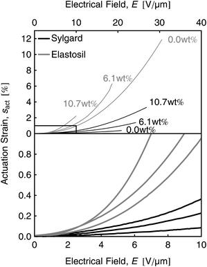 | ||
| Fig. 9 Denoised actuation strain sz(E) curves for Sylgard and Elastosil films with 0.0 wt%, 6.1 wt% and 10.7 wt% dipole content. The inset magnifies the fitting region for the sensitivities β. | ||
| Sylgard | Elastosil | |||
|---|---|---|---|---|
| a [ν] = wt%, [β] = 10−3% V−2 μm2 | ||||
| ν | β mat | β act | β mat | β act |
| 0.0 | 0.76 ± 0.04 | 0.88 | 6.94 ± 0.34 | 9.14 |
| 6.1 | 2.07 ± 0.05 | 2.26 | 17.16 ± 0.65 | 12.14 |
| 10.7 | 4.08 ± 0.04 | 3.92 | 26.35 ± 1.68 | 18.17 |
Conclusion
In conclusion, two off-the-shelf silicone kits, Sylgard 184 by Dow Corning and Elastosil RT 625 by Wacker Silicones, were modified on the molecular level using a one step film formation process. DSC, FT-IR and 13C-NMR spectroscopy showed that strong organic dipoles were homogeneously distributed in both elastomer matrices and covalently bound to the network. The introduced push–pull dipole enhances the relative permittivity. At the same time the mechanical stiffness and the electrical breakdown are decreased. This results in an increased electromechanical sensitivity which was confirmed by detailed material characterization and independently performed actuation measurements with pure shear actuators. This versatile approach is suitable for stiff and quite soft silicone networks, which undergo Pt-catalysed network forming reaction. The manufacturing route introduced here can be easily applied to already existing silicone based actuator and energy harvesting technologies on an industrial scale, although the exact chemistry of the used off-the-shelf silicones is unknown.Acknowledgements
The authors are grateful to funding from the German government, which contributed in the German WING program within the NanoFutur-KompAkt (FKZ: 03X5511) and PowerAct project (FKZ:13N10684 and 13N10685). We also thank R. Krause and T. Meissner for help in the laboratories as well as M. Ehlert for performing DSC measurements.References
- E. Biddiss and T. Chau, Dielectric elastomers as actuators for upper limb prosthetics: challenges and opportunities, Med. Eng. Phys., 2008, 30(4), 403–418 CrossRef.
- Y. Bar-Cohen and C. Breazeal, ed., Biologically inspired intelligent robots. SPIE Press, Bellingham, 2003 Search PubMed.
- R. E. Pelrine, R. D. Kornbluh and J. P. Joseph, Electrostriction of polymer dielectrics with compliant electrodes as a means of actuation, Sens. Actuators, A, 1998, 64(1), 77–85 CrossRef.
- Y. Bar-Cohen, ed., Electroactive polymer (EAP) actuators as artificial muscles: reality, potential, and challenges. SPIE Press, Bellingham, 2004 Search PubMed.
- P. Brochu and Q. Pei, Advances in dielectric elastomers for actuators and artificial muscles, Macromol. Rapid Commun., 2010, 31(1), 10–36 CrossRef CAS.
- G. Kovacs, P. Lochmatter and M. Wissler, An arm wrestling robot driven by dielectric elastomer actuators, Smart Mater. Struct., 2007, 16(2), 306–317 CrossRef.
- C. Jordi, S. Michel, G. Kovacs and P. Ermanni, Scaling of planar dielectric elastomer actuators in an agonist-antagonist configuration, Sens. Actuators, A, 2010, 161(1–2), 182–190 CrossRef.
- S. Döring, M. Kollosche, T. Rabe, J. Stumpe and G. Kofod, Electrically tunable polymer dfb laser, Adv. Mater., 2011, 23(37), 4265–4269 CrossRef.
- G. Jordan, D. N. McCarthy, N. N. Schlepple, J. Krissler, H. Schröder and G. Kofod, Actuated micro-optical submount using a dielectric elastomer actuator, IEEE/ASME Trans. Mechatron., 2011, 16, 98–102 CrossRef.
- K. Ahnert, M. Abel, M. Kollosche, P. J. Jorgensen and G. Kofod, Soft capacitors for wave energy harvesting, J. Mater. Chem., 2011, 21, 14492–14497 RSC.
- H. Stoyanov, D. N. McCarthy, M. Kollosche and G. Kofod, Dielectric properties and electric break down strength of a subpercolative composite of carbon black in thermoplastic copolymer, Appl. Phys. Lett., 2009, 94, 232905 CrossRef.
- G. C. Psarras, E. Manolakaki and G. M. Tsangaris, Dielectric dispersion and ac conductivity in iron particles loaded-polymer composites, Composites, Part A, 2003, 34(12), 1187–1198 CrossRef.
- M. Molberg, D. Crespy, P. Rupper, F. Nüesch, J. A. E. Månson, C. Löwe and D. M. Opris, High breakdown field dielectric elastomer actuators using encapsulated polyaniline as high dielectric constant filler, Adv. Funct. Mater., 2010, 20(19), 3280–3291 CrossRef CAS.
- G. Gallone, F. Carpi, D. De Rossi, A. Levita and G. Marchetti, Dielectric constant enhancement in a silicone elastomer filled with lead magnesium niobate-lead titanate, Mater. Sci. Eng., C, 2007, 27, 110–116 CrossRef CAS.
- A. Patsidis and G. C. Psarras, Dielectric behaviour and functionality of polymer matrix – ceramic BaTiO3 composites, eXPRESS Polym. Lett., 2008, 2, 718–726 CrossRef CAS.
- D. N. McCarthy, S. Risse, P. Katekomol and G. Kofod, The effect of dispersion on the increased relative permittivity of TiO2/SEBS composites, J. Phys. D: Appl. Phys., 2009, 42, 145406 CrossRef.
- H. Stoyanov, M. Kollosche, S. Risse, D. N. McCarthy and G. Kofod, Elastic block copolymer nanocomposites with controlled interfacial interactions for artificial muscles with direct voltage control, Soft Matter, 2011, 7, 194–202 RSC.
- B. Kussmaul, S. Risse, G. Kofod, R. Wache, M. Wegener, D. N. McCarthy, H. Krüger and R. Gerhard, Enhancement of dielectric permittivity and electromechanical response in silicone elastomers: Molecular grafting of organic dipoles to the macromolecular network, Adv. Funct. Mater., 2011, 21(23), 4589–4594 CrossRef CAS.
- S. C. Yang and W. H. Chung, Palladium-catalyzed N-allylation of anilines by direct use of allyl alcohols in the presence of titanium(IV) isopropoxide, Tetrahedron Lett., 1999, 40(5), 953–956 CrossRef CAS.
- E. Tuncer, D. R. James, I. Sauers, A. R. Ellis and M. O. Pace, On dielectric breakdown statistics, J. Phys. D: Appl. Phys., 2006, 39(19), 4257–4268 CrossRef CAS.
- F. Carpi, P. Chiarelli, A. Mazzoldi and D. de Rossi, Electromechanical characterisation of dieletric elastomer planar actuators: comparative evaluation of different electrode materials and different counterloads, Sens. Actuators, A, 2003, 107(1), 85–95 CrossRef.
- A. L. Larsen, K. Hansen, P. Sommer-Larsen, O. Hassager, A. Bach, S. Ndoni and M. Jorgensen, Elastic properties of nonstoichiometric reacted pdms networks, Macromolecules, 2003, 36(26), 10063–10070 CrossRef CAS.
- K. H. Stark and C. G. Garton, Electric strength of irradiated polythene, Nature, 1955, 176(4495), 1225–1226 CrossRef.
- M. Kollosche and G. Kofod, Electrical failure in blends of chemically identical, soft thermoplastic elastomers with different elastic stiffness, Appl. Phys. Lett., 2010, 96(7), 071904 CrossRef.
| This journal is © The Royal Society of Chemistry 2012 |
