Absorption layers of ink vehicles for inkjet-printed lines with low electrical resistance
Changjae
Kim
ab,
Masaya
Nogi
*b,
Katsuaki
Suganuma
b,
Yukie
Saitou
c and
Jun
Shirakami
c
aDepartment of Adaptive Machine Systems, Graduate school of Engineering, Osaka University, Yamadaoka 2-1, Suita, Osaka, Japan
bThe Institute of Scientific and Industrial Research, Osaka University, Mihogaoka 8-1, Ibaraki, Osaka, Japan. E-mail: nogi@eco.sanken.osaka-u.ac.jp; Fax: +81-6-6879-8522; Tel: +81-6-6879-8521
cPolymer Technical Group 2, Polymer Technical Div.2, DIC Corporation, 3, Takasago 1-chome, Takaishi, Osaka, Japan
First published on 17th July 2012
Abstract
Low concentrations of metallic nanoparticle inks often produce a coffee-ring effect, thereby resulting in high electrical resistance in inkjet-printed lines. The coffee-ring effect is due to a convection flow of ink droplets and can be overcome by reducing the flow. Here we report the formation of absorption layers of ink vehicles on pristine polyimide films and fabrication of convex-shaped lines without the coffee-ring effect even if a low concentration of commercially available ink is used. The coated layers increased the ink concentration and prevented a convection flow of ink droplets. As a result, the electrical resistance of the inkjet-printed lines on polymer-coated polyimide films (8 Ω) was improved threefold over that of lines printed on pristine polyimide films (24 Ω). This is a similar improvement to inkjet-printed lines that were heated gradually (7 Ω), which is one of the methods that can reduce convection flow. Durability tests were conducted and electrical resistance was measured on inkjet-printed lines on polymer-coated polyimide films. Even under harsh environments, the lines showed excellent electrical performance, and they can easily be integrated into practical applications.
Introduction
Printing techniques have received considerable attention as one of the most promising alternatives to conventional techniques for producing conductive lines used in electronic devices. A major challenge in printed electronics is producing highly conductive lines with narrow, sharp edges. Among the numerous printing technologies, screen printing can produce such lines. This is because highly-concentrated metallic nanoparticle ink is pressed by a roller or squeegee onto the printing surface through a pre-patterned mask that has narrow, sharp edges.1–3 Organic electronic devices, which are one of the most anticipated future devices, also need to form thin layers for use as organic semiconductors or insulators on substrates. Screen printing, with its firm-contact printing technique required to produce patterns, would damage the patterns or the deposited components on the substrates. Therefore, to avoid damage, the fabrication of conductive lines or electrodes using a mask-less noncontact method, such as inkjet printing, is preferred over screen printing.4–8However, it is difficult to produce highly conductive lines with narrow, sharp edges using inkjet printing. When conductive lines are formed by inkjet printing, the metallic nanoparticle inks are ejected through a small-diameter nozzle of approximately 50 μm. Therefore, low concentration and low viscosity inks are required for inkjet printing.9–14 When a low-concentrate ink is ejected from the nozzles, the morphology of the printed lines frequently has a rough shape with lateral spreading, splashing, and wavy boundaries. Increasing the ink concentration is effective; however, high-concentration ink is difficult to inject through an inkjet printer because it clogs the nozzle. Thus, surface-energy adjustment of the polymer substrates was an inevitable approach to obtain sharp, straight lines using inkjet printing.4,15–20
Even though sharp, straight lines could be printed on the optimized substrates, there is another problem while using a low-concentrate metallic nanoparticle ink, namely the-coffee ring effect.21,22 Metallic nanoparticles are segregated at the line edge by a solvent convection flow during drying of ink vehicles. As a result, inhomogeneous distributions of silver nanoparticles decreased the conductivity of the printed lines, and their conductivity decreased when the line width was decreased.6,23 Therefore, although inkjet printing has a few advantages for non-contact, mask-less printing, creating highly conductive lines with narrow, sharp edges was difficult because of the use of low concentration inks.
Here we report that highly conductive lines with narrow, sharp edges were achieved by inkjet printing with a commercially available silver nanoparticle ink of low concentration and low viscosity. Absorption layers of ink vehicles were formed on polyimide films. When the ink was inkjet-printed on such substrates, the concentration of silver nanoparticles in the printed lines increased. The absorption of ink vehicles brought the inkjet-printed lines into convex-shaped narrow lines with high conductivity. In addition, this technique enabled the sintering time to be shortened because the pre-sintering process, which is essential for solvent evaporation, does not require either flash or microwave sintering methods. These achievements can be applied to high-speed mass production of electronic devices using inkjet printing.
Experimental
Polyimide base substrates
Three types of substrates were used in this study: pristine polyimide films (Kapton 300H, DU PONT-TORAY CO., LTD, Japan), pore-structured polyimide films (DMI-70F, DIC Corp., Japan), and polymer-coated polyimide films (DMI-70, DIC Corp., Japan). The pore-structured substrate was fabricated by coating thermoplastic polymer mixed with silica nanoparticles of 10–20 nm diameter on the pristine polyimide films. Next, the polymer-coated polyimide films were fabricated by coating thermoplastic polymer onto the pristine polyimide films. In both coated polyimide films, thickness of the coating layer was approximately 10–13 μm.Silver nanoparticle ink and inkjet printing
Silver nanoparticle ink dispersed in an ethanol/ethylene glycol mixture was purchased from Cabot (CCI-300, Cabot Printing Electronics and Displays, USA). The silver ink contained 20 wt % silver nanoparticles, with the particle diameter ranging from 30 to 50 nm. The viscosity of the ink was 14.4 mPas. Inkjet printing was performed with a piezoelectric system (Dimatix DMP 2831, Dimatix- Fujifilm Inc., USA) equipped with a 10 pL cartridge (DMC-11610). The silver-nanoparticle ink was impacted at a voltage of 22 V and a frequency of 5 kHz using a customized waveform. The substrate was maintained at room temperature during printing; the distance between the substrate and the nozzle was set to 1 mm, and dot spacing was set at 20 μm. The length of printed lines was 40 mm. After printing, these lines were heated at 200 °C for 30 min in air.Characterizations of inkjet-printed lines
A metal mask was set on the printed lines, and gold was deposited by gold sputtering (Mild Sputter E-1045, Hitachi High-Technologies Corp., Japan). As a result, four probe pads (1 × 1 mm2) were fabricated on the printed lines at 5-mm intervals. Using the pads, electrical resistance of the printed lines was measured by the four-point probe method (34410A, Agilent, USA). The printed lines were observed with a 3D microscope (VK-9500, KEYENCE, Japan), or with a field emission scanning electron microscope (FE-SEM; JSM-6700F, JEOL Ltd., Japan) at an accelerating voltage of 5.0 kV and a working distance of 7–8 mm.A crosshatch-adhesion test was applied to evaluate the adhesion of silver ink on the polyimide-based substrates. This test was performed by applying and removing a pressure-sensitive tape (CT-18, NICHIBAN CO., LTD., Japan) over the cut areas (30 × 20 mm2) in the film and were measured using the ASTM D3359-B standard.24 The crosshatch patterns (1 × 1 mm2) were formed by using a cross-cut guide (CCJ-1, COTEC Corp., Japan). In this standard the scale is from 0B to 5B, where 5B indicates the best adhesion.
Three types of thermal reliability tests (high-temperature storage, thermal shock, and high-temperature and humidity-exposure tests) were conducted under an air atmosphere for 1000 h. A high-temperature storage test was read at 80 °C using an environmental chamber (ST-110, ESPEC Corp., Japan). A thermal-shock test was performed at temperatures between −40 °C and 80 °C using two specially designed heating/cooling chambers (TSE-11-A-S, ESPEC Corp., Japan). The dwelling time was 30 min with the temperature reaching the target temperature within 10 min. High-temperature and humidity-exposure tests were performed at 85 °C/85% relative humidity (RH) using an environmental chamber (SH-241, ESPEC Corp., Japan). Electrical resistance was measured by the four-point probe method every 100 h.
Results and discussions
When low concentration silver-nanoparticle ink was inkjet printed on a pristine polyimide film, straight, sharp edged lines 80 μm wide were obtained (Fig. 1a). Due to the low concentration of silver nanoparticles, the as-printed lines were high at 3.7 μm. After heating at 200 °C for 30 min, the line cross-sectional profiles became concave in shape while maintaining their width (Fig. 1b). During heating, ink vehicles with convection flow evaporated and the silver nanoparticles aggregated at the line edges.21,22 The inhomogeneous distribution of nanoparticles produced large voids at the center of the lines, which caused a loss of electrical contact between silver nanoparticles.23 As a result, the heated lines on a pristine polyimide film exhibited a high electrical resistance of 24 Ω, which was ten times greater than that of bulk silver with the same line dimensions.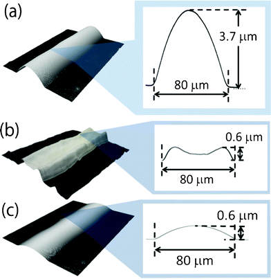 | ||
| Fig. 1 (a) An as-printed line on a pristine polyimide film before heating. (b) After constant heating at 200 °C for 30 min, a concave-shaped line with a high resistance of 24 Ω. (c) After gradual heating from 20 °C to 200 °C at a rate of 3 °C min−1 and maintaining for 30 min, a convex-shaped line with a low resistance of 7 Ω. | ||
In our previous research, we reported that high concentration silver nanoparticle ink achieved a low electrical resistance even when it was heated at a constant temperature.23 This was because such high-concentration inks do not produce convection flow during evaporation of ink vehicles. Thus, we proposed gradual heating for a low-concentration silver-nanoparticle ink to increase their concentration gradually without causing an inhomogeneous distribution of silver nanoparticles.23 When we subjected a printed line to a gradual temperature elevation to 200 °C over 60 min, and subsequently constant heating at 200 °C for 30 min, the heated lines exhibited a convex shape (Fig. 1c). As a result, the line had a low electrical resistance of 7 Ω, which is equivalent to that of bulk silver. However, this prolonged heating is impractical because printed electronic devices need to be fabricated using high-volume, high-speed methods such as roll-to-roll processes. Therefore, in this article we suggest that surface-coating treatments can create inkjet-printed lines with low electrical resistance without prolonged heating. The basic concept is that the coating layer on the substrate increases the concentration of silver-nanoparticle ink before heating and convex printed lines with low resistance are obtained after heating.
The pore-structured coating layer was formed on the pristine polyimide film by a thermoplastic polymer mixed with silica nanoparticles of 10–20 nm in diameter. When the silver-nanoparticle ink was inkjet-printed on the pore-structured coating layer and heated at 200 °C for 30 min, the obtained lines were convex in shape (Fig. 2a). The width (60 μm) and height (0.5 μm) of the lines were much smaller than lines printed on pristine polyimide (Fig. 1c and 2a). The diameter of the silver nanoparticles in the ink was 30–50 nm, whereas the pore size of the coating layer was approximately 100 nm in diameter (Fig. 2b). Therefore, immediately after inkjet printing and before heat sintering, most of the silver nanoparticles flowed into the pore structures. Consequently, the inflow of silver nanoparticles into the pore structures created a loss of the electrical connection between adjacent silver nanoparticles.25 Finally, the heated lines on the pore structures exhibited a high electrical resistance of 16 Ω, in spite of their convex shape. In general, silver nanoparticles of less than 100 nm in diameter are used in inkjet printing as conductive ink. In contrast, the diameter of the pore structures was approximately equal to 100 nm, although they were fabricated with tiny nanoparticles with a diameter of 10–20 nm. It would be ideal if mechanical sieving of silver nanoparticles through the fine pores would increase the concentration of silver nanoparticles and the electrical conductivity of inkjet-printed lines.
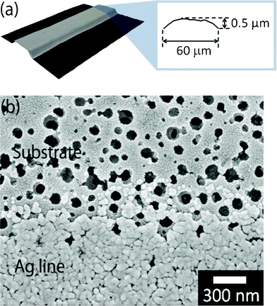 | ||
| Fig. 2 (a) Convex-shaped line with a large resistance of 16 Ω after heating at 200 °C for 30 min. (b) Observation by FE–SEM of the surface of a porous-structured polyimide substrate (upper) and inkjet-printed line of silver-nanoparticle ink (lower). | ||
Therefore, we formed a coating layer that can absorb only ink vehicles on the pristine polyimide films. It induced an increase in the concentration of silver-nanoparticle ink when low concentration inks were printed on the substrates. As a preliminary experiment, we already observed that the polymer-coated polyimide films absorbed ethanol effectively. As mentioned above, ethanol is the main component of the ink. There were no pores on the coating layer that could be penetrated by silver nanoparticles. Therefore, when silver-nanoparticle ink is printed on the polymer-coated polyimide films, their concentration is increased by absorption of only the ink vehicles. Consequently, highly concentrated inks should impart convex-shaped lines with low resistance and without undergoing heating.
When the silver-nanoparticle ink was inkjet-printed on the polymer-coated polyimide and then heated at a constant temperature of 200 °C for 30 min, the heated lines showed the convex shape 70 μm wide and 1.3 μm high (Fig. 3a). Their width was smaller than those on pristine polyimide because the highly concentrated inks produce narrower lines. However, their height of 1.3 μm was significantly greater compared to those printed on pristine polyimide, which were only 0.6 μm. Observations by FE–SEM on the edge of the inkjet-printed lines revealed that the coated polymer layer swelled to approximately 1 μm in thickness (Fig. 3b). Furthermore, a cross-sectional FE–SEM observation showed that the silver nanoparticles and the coated polymer layer were not clearly merged (Fig. 3c). As expected, the coated polymer absorbed only the ink vehicle and not the silver nanoparticles. After heating, all the silver nanoparticles remained on the surface of the coated layer, and they were densely packed together. As a result, heated lines on polymer-coated polyimide showed a small resistance of only 8 Ω, even after constant heating at 200 °C for 30 min. These results suggested that when the substrates were coated with a certain polymer that could absorb the ink vehicles, the printed lines resulted in enhanced electrical conductivity, even though the inkjet-printed lines were heated at a constant temperature. Recently, researchers have focused on photonic- and microwave-exposure techniques on roll-to-roll compatible sintering due to the significantly short sintering time of these techniques.26 However, these exposure processes require pre-sintering of the printed wet lines for dozens of minutes to prevent an ink explosion during exposure.26,27 Therefore, the coating layer system of absorbing the ink vehicles might also be effective for photonic and microwave exposure as a pre-sintering process.
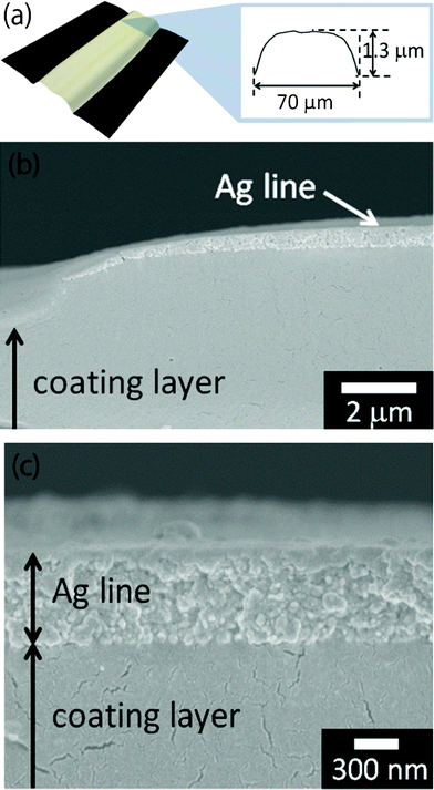 | ||
| Fig. 3 (a) A Convex-shaped line with a low resistance of 8 Ω after heating at 200 °C for 30 min. (b) Cross-sectional FE–SEM observation of heated lines on a polymer-coated polyimide film. (c) Cross-sectional FE–SEM observation of silver nanoparticles and a coated polymer layer of the heated lines. | ||
Finally, we conducted adhesion and thermal reliability tests of inkjet-printed lines with the silver nanoparticle ink on the polymer-coated polyimide film for durability evaluation. Adhesion strength was estimated according to the international standard of ASTM D3359-B. As shown in Fig. 3c, the heated silver nanoparticles were clearly separated from the coating layer without any merging. However, the heated silver nanoparticles did not peel from the coating layer after the adhesion test (Fig. 4). This result corresponds to the 5B level of adhesion strength and means that the coated polymer layer adhered well with not only the polyimide substrate but also with the silver nanoparticle lines after sintering. Moreover, the inkjet-printed lines on the polymer-coated polyimide film were subjected to three different thermal-reliability tests. After each test, the electrical resistance of the inkjet-printed lines was measured (Fig. 5). When the printed lines were subjected to a high-temperature-storage test at 80 °C, electrical resistance of the lines decreased to 87% at 100 h, which was then maintained at 82–88% until reaching 1000 h. A drastic decrease within 100 h implied that the electrical contacts between silver nanoparticles were increased by the high temperature storage at 80 °C. Both the thermal shock test (−40 °C and 80 °C) and the high-temperature and humidity-exposure tests (85 °C and RH 85%) slightly increased their electrical resistance down to less than 20% over the increasing time duration until 1000 h. These results revealed that the inkjet-printed lines on polymer-coated substrates could be used for common applications based on their durability.
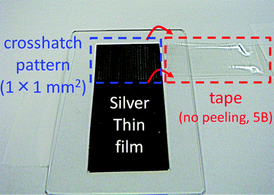 | ||
| Fig. 4 Adhesion test of the inkjet-printed lines on the polymer-coated polyimide film. | ||
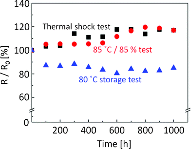 | ||
| Fig. 5 Thermal-reliability tests of inkjet-printed lines with the silver-nanoparticle ink on the polymer-coated polyimide film. Triangle: high-temperature storage at 80 °C, Square: thermal-shock test at −40 °C and 80 °C, Circle: high-temperature and humidity-exposure test at 85 °C and RH 85%. | ||
Conclusion
A low concentration of silver-nanoparticle ink was used for inkjet-printing. During heating inkjet-printed lines for sintering, a convection flow of ink droplets was produced, resulting in inhomogeneous distributions of silver nanoparticles within the lines. Consequently, the inkjet-printed lines exhibited high electrical resistance. In this article, two different absorption layers were coated on the polyimide films to fabricate low electrical resistance of inkjet-printed lines without the coffee ring effect. The first absorption layer is a pore-structured polyimide film. Silver nanoparticles of 30–50 nm in diameter were mechanically sieved through fine pores. Although the fine pores were fabricated with silica nanoparticles of diameter 10–20 nm, the pore size was much larger than the silver nanoparticles. Therefore, the silver nanoparticles flowed into the pore-structures resulting in the electrical resistance of the printed lines being significantly higher than lines on the pristine polyimide film. When the pore structures are fabricated on the plastic film to obtain low-resistance printed lines, chemical repellent treatments should be applied.25 The second absorption layer studied was a polymer coating on the polyimide film that could absorb the ink vehicles. The absorption of ink vehicles increased the ink concentration and prevented a convection flow of silver nanoparticles while the inkjet-printed lines were heated. As a result, most of the silver nanoparticles remained on the surface and convex-shaped lines with low electrical resistance were obtained. Moreover, the inkjet-printed lines on the coating layer adhered well with the polyimide films against the cross-hatch adhesion test and exhibited high thermal reliability against temperature storage, thermal shock, high temperature and high humidity exposure tests. As mentioned above, this technique has various advantages. In addition to its merits, this technique may also increase the potential costs for production because the process of forming a coating layer is needed before inkjet printing. However, the problem would be overcome with the use of high-volume, high-speed methods such as roll-to-roll processes.References
- W. Y. Chang, T. H. Fang, H. J. Lin, Y. T. Shen and Y. C. Lin, J. Disp. Technol., 2009, 5, 178–183 CrossRef.
- R. Faddoul, N. Reverdy-Bruas and J. J Bourel, J. Mater. Sci.: Mater. Electron., 2011, 1–12 Search PubMed.
- G. Zhang, P. Deng, W. Xu and Z. Yu, 2011 China Academic Conference on Green Printing and Packaging Materials, 2012, 380, 121–124 Search PubMed.
- T. H. J. Van Osch, J. Perelaer, A. W. M. De Laat and U. S. Schubert, Adv. Mater., 2008, 20, 343–345 CrossRef CAS.
- B. J. De Gans, P. C. Duineveld and U. S. Schubert, Adv. Mater., 2004, 16, 203–213 CrossRef CAS.
- D. Kim, S. Jeong, B. K. Park and J. Moon, Appl. Phys. Lett., 2006, 89, 264101 CrossRef.
- B. K. Park, D. Kim, S. Jeong, J. Moon and J. S. Kim, Thin Solid Films, 2007, 515, 7706–7711 CrossRef CAS.
- J. Choi, Y. J. Kim, S. Lee, S. U. Son, H. S. Ko, V. D. Nguyen and D. Byun, Appl. Phys. Lett., 2008, 93, 193508 CrossRef.
- H. C. Jung, S. H. Cho, J. W. Joung and Y. S. Oh, J. Electron. Mater., 2007, 36, 1211–1218 CrossRef CAS.
- H. H. Lee, K. S. Chou and K. C. Huang, Nanotechnology, 2005, 16, 2436–2441 CrossRef CAS.
- J. Perelaer, A. W. M. De Laat, C. E. Hendriks and U. S. Schubert, J. Mater. Chem., 2008, 18, 3209–3215 RSC.
- J. Perelaer, B. J. De Gans and U. S. Schubert, Adv. Mater., 2006, 18, 2101–2104 CrossRef CAS.
- A. L. Dearden, P. J. Smith, D. Y. Shin, N. Reis, B. Derby and P. O'Brien, Macromol. Rapid Commun., 2005, 26, 315–318 CrossRef CAS.
- J. Perelaer, C. E. Hendriks, A. W. M. De Laat and U. S. Schubert, Nanotechnology, 2009, 20, 165303 CrossRef.
- J. H. Oh and S. Y. Lim, J. Micromech. Microeng., 2010, 20, 015030 CrossRef.
- S. H. Lee, K. Y. Shin, J. Y. Hwang, K. T. Kang and H. S. Kang, J. Micromech. Microeng., 2008, 18, 075014 CrossRef.
- Y. S. Goo, Y. I. Lee, N. Kim, K. J. Lee, B. Yoo, S. J. Hong, J. D. Kim and Y. H. Choa, Surf. Coat. Technol., 2010, 205, S369–372 CrossRef CAS.
- G. Tortissier, P. Ginet, B. Daunay, L. Jalabert, P. Lambert, B. Kim, H. Fujita and H. Toshiyoshi, J. Micromech. Microeng., 2011, 21, 105021 CrossRef.
- A. M. J. Van Den Berg, A. W. M. De Laat, P. J. Smith, J. Perelaer and U. S. Schubert, J. Mater. Chem., 2007, 17, 677–683 RSC.
- B. J. Kang and J. H. Oh, Thin Solid Films, 2010, 518, 2890–2896 CrossRef CAS.
- J. Park and J. Moon, Langmuir, 2006, 22, 3506–3513 CrossRef CAS.
- D. D. Robert, B. Olgica, F. D. Todd, H. Greb, R. N. Sidney and A. W. Thomas, Nature, 1997, 389, 827–829 CrossRef.
- C. Kim, M. Nogi and K. Suganuma, J. Micromech. Microeng., 2012, 22, 035016 CrossRef.
- ASTM D3359, Standard Test Methods for Measuring Adhesion by Tape Test, ASTM, 1998, 7p Search PubMed.
- C. Kim, M. Nogi, K. Suganuma and Y. Yamato, ACS Appl. Mater. Interfaces, 2012, 4, 2168–2173 CAS.
- J. Perelaer, R. Abbel, S. Wünscher, R. Jani, T. Lammeren and U. S. Schubert, Adv. Mater., 2012, 24, 2620–2625 CrossRef CAS.
- D. J. Lee, S. H. Park, S. Jang, H. S. Kim, J. H. Oh and Y. W. J. Song, J. Micromech. Microeng., 2011, 21, 125023 CrossRef.
| This journal is © The Royal Society of Chemistry 2012 |
