Synthesis and electrochemical properties of LiNi0.5Mn1.5O4 as a 5 V cathode material for lithium ion batteries
Yichen
Dong
ab,
Zhenbo
Wang
*a,
Hua
Qin
c and
Xulei
Sui
a
aSchool of Chemical Engineering and Technology, Harbin Institute of Technology, Harbin, 150001, PR China. E-mail: wangzhenbo1008@ yahoo.com.cn
bHulunbeier Vocational Technical College, Hulunbeier, 021000, PR China
cCollege of Resource and Environment Engineering, Heilongjiang Institute of Science and Technology, Harbin, 150027, PR China
First published on 3rd October 2012
Abstract
LiNi0.5Mn1.5O4 as a 5 V cathode material for a lithium-ion battery was synthesized by solution evaporation process in this paper. Thermal gravimetric analysis of the precursor compounds was carried out. X-ray diffraction and scanning electron microscope were used for studying the structure and the morphology of the LiNi0.5Mn1.5O4 materials. Cyclic voltammograms and charge–discharge curves were obtained for presenting the electrochemical performances of LiNi0.5Mn1.5O4. Experimental results show that the discharge capacity and capacity retention of the LiNi0.5Mn1.5O4 prepared by solution evaporation process are superior to the LiNi0.5Mn1.5O4 obtained by melting salt method. The effects of different sintering temperatures on the electrochemical properties of the LiNi0.5Mn1.5O4 electrode materials synthesized by a solution evaporation process were also systematically investigated. With the raising of the sintering temperature, the size of the LiNi0.5Mn1.5O4 gradually increases, its crystallinity is enhanced and the surface morphology of grain is gradually neatened. Electrochemical test results show that the LiNi0.5Mn1.5O4 prepared at 800 °C has the best cycle reversibility, the highest discharge capacity and the optimal capacity retention.
1. Introduction
Lithium-ion secondary batteries with the advantages of high working voltages, large energy densities, small volumes, no memory effect and long cycling lifetimes have been in the research spotlight.1,2 At present, the main research is on cathode materials of LiCoO2, LiNiO2, LiMn2O4 and their derivatives. LiMn2O4 exhibits a pure cubic spinel structure (Fd3m). Due to the rich resource of Mn, low toxicity, low environmental pollution, cheap raw material price and its simple and easy to control synthesis, it is considered one of the most promising cathode materials, especially for the power batteries and stored energy batteries. However, LiMn2O4 has the shortcoming of large capacity fade on cycling at high temperatures (over 60 °C) due to the Jahn–Teller effect of Mn3+ and electrolyte undergoes easy oxidative decomposition on it.3 Therefore, researchers usually adopt doped transition metal ions in LiMn2O4 to form LiMxMn2 − xO4 (M = Cr, Ni, Cu, Fe, etc.) materials with a spinel structure.4,5 This may also inhibit the Jahn–Teller effect and improve its cycling behavior. In these materials, LiNi0.5Mn1.5O4 exhibits a high voltage plateau at about 4.7 V in the discharge process, great capacity retention at high temperatures (over 60 °C), low cost of raw material and is environmentally friendly, so it is considered to be one of the promising cathode materials for lithium ion batteries.6–8Several methods to synthesize the LiNi0.5Mn1.5O4 compound have been reported in many groups, such as the solid-state method,9 molten salt method,10 sol–gel method,11 composite carbonate process,12 emulsion drying method13 and ultrasonic spray pyrolysis method,14etc. Although LiNi0.5Mn1.5O4 as a cathode material for lithium-ion batteries with good electrochemical performances may be synthesized by these methods, there are some unfavorable factors with the high cost of raw materials and the complex process in preparation for commercial production.
Due to the use of low-melting lithium salts as a co-solvent in the molten salt method, much higher diffusion rates between reaction components and higher purity LiNi0.5Mn1.5O4 powder with a single phase may be obtained and show good electrochemical properties 15. Its defects not only make the process complex during washing co-solvent, but also result in environmental pollution. Both of them limit the industrialized production of this method. In this paper, we use a novel, simple, environmental friendly and low energy-consuming method denoted as a solution evaporation process to synthesize LiNi0.5Mn1.5O4 material for lithium ion batteries. Effects of calcining times on electrochemical performances of LiNi0.5Mn1.5O4 synthesized by the solution evaporation process have also been investigated.
2. Experimental
2.1. LiNi0.5Mn1.5O4 composite synthesis
To synthesize LiNi0.5Mn1.5O4 composite by a solution evaporation process, LiNO3, Ni(NO3)2·6H2O, and Mn(CH3COO)2·4H2O were used as the raw materials. After grinding in an agate mortar, the mixture was put into a water bath at 80 °C, and then some ethanol and ammonia water of 15.0 mol L−1 was added with mechanical agitation until the solid state composite was obtained. The precursor was dried at 120 °C for 2 h in a vacuum drying oven and then calcined at 400 °C for 4 h in an oxygen atmosphere to decompose nitrate and acetate. The LiNi0.5Mn1.5O4 composite was obtained after the precursor was sintered at 800 °C for 6 h in an oxygen atmosphere and then calcined at 600 °C for 2 h in an oxygen atmosphere. The LiNi0.5Mn1.5O4 composite from the molten salt method was synthesized on the basis of ref. 16.2.2. Characterization of material
Thermal decomposition behavior of the starting mixture precursor was examined by thermal gravimetric analysis (TGA). TGA was carried out on a Mettler-Toledo (TGA/SDTA851) thermal analyzer in air at a heating rate of 10° min−1 with a temperature range from room temperature to 1000 °C.The powder X-ray diffraction (XRD, D/max-RB, Japan) patterns were obtained using a Cu Kα X-ray source operating at 45 kV and 100 mA at a scanning rate of 4° min−1 with an angular resolution of 0.05°. The morphologies of the as-prepared samples were presented by a Quanta-200 scanning electron microscope (SEM).
2.3. Electrochemical performance test
The electrochemical performances of the as-prepared samples were evaluated with coin-type cells (CR 2025) with a metallic lithium sheet as an anode electrode and reference electrode at room temperature. The cells were assembled by a layer of Celgard 2400 polypropylene microporous membrane as a separator to separate the cathode from the anode with a liquid electrolyte of 1 mol L−1 LiPF6 in ethylene carbonate (EC)–dimethyl carbonate (DMC) (1![[thin space (1/6-em)]](https://www.rsc.org/images/entities/char_2009.gif) :
:![[thin space (1/6-em)]](https://www.rsc.org/images/entities/char_2009.gif) 1, v/v) with some additives. The active LiNi0.5Mn1.5O4 composite of 80 wt%, 10 wt% conductive acetylene black, and 10 wt% polyvinylidene fluoride (PVDF) binder homogeneously mixed in N-methylpyrrolidinone (NMP) were prepared into viscous slurries for efficient deposition. The slurry was deposited on a current collector of aluminium foil by a blade. After drying in a vacuum oven at 100 °C for 5 h, the cells were assembled in a glovebox filled with pure argon. Charge/discharge tests were performed at a constant current density in different discharge rates with the potential range between 3.0 and 4.9 V using a NEWARE BTS-5. Cycle voltammetric tests were conducted on CHI604C electrochemical workstation with a potential range from 3.5 to 4.9 V at a scanning rate of 0.05 mV s−1.
1, v/v) with some additives. The active LiNi0.5Mn1.5O4 composite of 80 wt%, 10 wt% conductive acetylene black, and 10 wt% polyvinylidene fluoride (PVDF) binder homogeneously mixed in N-methylpyrrolidinone (NMP) were prepared into viscous slurries for efficient deposition. The slurry was deposited on a current collector of aluminium foil by a blade. After drying in a vacuum oven at 100 °C for 5 h, the cells were assembled in a glovebox filled with pure argon. Charge/discharge tests were performed at a constant current density in different discharge rates with the potential range between 3.0 and 4.9 V using a NEWARE BTS-5. Cycle voltammetric tests were conducted on CHI604C electrochemical workstation with a potential range from 3.5 to 4.9 V at a scanning rate of 0.05 mV s−1.
3. Results and discussion
3.1 Effect of synthetic method on performance of LiNi0.5Mn1.5O4 composite
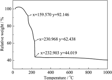
Fig. 1 shows the thermal gravimetric analysis (TGA) for the mixture precursor of Li–Ni–Mn. When the temperature reaches 233 °C, the weight loss of the mixture precursor is 44.02%. In this temperature range, ethanol and crystal water are evaporated, and ammonia water, acetate and nitrate are decomposed. From 600 °C to 1000 °C, the TG plot presents a slight weight loss, indicating that the LiNi0.5Mn1.5O4 sample has been synthesized. | ||
| Fig. 1 The TG curve of the mixture precursor of Li–Ni–Mn in air atmosphere (heating rate: 10 °C min−1). | ||
Fig. 2 shows the X-ray diffraction patterns of the as-prepared samples synthesized by different methods. The LiNi0.5Mn1.5O4 material obtained by the solution evaporation process in Fig. 2(a) shows a well-defined cubic spinel structure with Fd3m. Compared with the XRD pattern of the standard spinel LiNi0.5Mn1.5O4, every peak position is identical. However, LiNi0.5Mn1.5O4 synthesized by the melting salt method as shown in Fig. 2(b) displays nickel oxide impurities at 2θ of 20.92°, 37.49°, 43.43°, 66.16° and 69.43°.
 | ||
| Fig. 2 XRD patterns of the as-prepared samples synthesized by the solution evaporation process (a) and melting salt method (b). | ||
Fig. 3(a) and (b) show the SEM images of the LiNi0.5Mn1.5O4 material synthesized by the melting salt method, which were taken at different magnifications. It can be seen from Fig. 3 (a) and (b) that the material with the irregular surface appearance presents severe agglomeration. The LiNi0.5Mn1.5O4 composite synthesized by the solution evaporation process (Fig. 3(c) and (d)) taken at various magnifications presents a slightly increasing particle size and evidently different surface morphologies compared with the LiNi0.5Mn1.5O4 composite prepared by the melting salt method.
 | ||
| Fig. 3 SEM images of the LiNi0.5Mn1.5O4 materials prepared by the melting salt method (a, b) and solution evaporation process (c, d). | ||
Fig. 4 shows the cyclic voltammograms of LiNi0.5Mn1.5O4 synthesized by different methods at 1 C rate after 50 cycles between 3.0 and 4.9 V at 25 °C. The LiNi0.5Mn1.5O4 synthesized by the solution evaporation process shows better cycle reversibility than that by the melting salt method. The two materials all show two redox peaks at around 4.7 V and 4.1 V during the cyclic voltammograms process, which are attributed to the Ni2+/4+ and Mn3+/4+ redox, respectively.
 | ||
| Fig. 4 Cyclic voltammograms of LiNi0.5Mn1.5O4 synthesized by different methods at 1 C after 50 cycles. | ||
The discharge capacities of the LiNi0.5Mn1.5O4 materials synthesized by different methods were studied at 1 C charge–discharge rate in the range from 3.0 to 4.9 V. As an example, a selection of the twentieth charge—discharge curves of the samples synthesized by different methods at 1 C are plotted in Fig. 5. It can be seen that the LiNi0.5Mn1.5O4 synthesized by the solution evaporation process shows a larger plateau in the 4.7 V region and a smaller plateau about at 4.0 V, which are attributed to Ni2+/4+ and Mn3+/4+, respectively. It is in accordance with the results of the CV test. However, the LiNi0.5Mn1.5O4 composite synthesized by the melting salt method shows a slight low plateau in the 4.6 V region. From the results above, discharge capacity and reversibility of the LiNi0.5Mn1.5O4 prepared through the solution evaporation process is superior to that by the melting salt method.
 | ||
| Fig. 5 Twentieth charge–discharge curves of LiNi0.5Mn1.5O4 composites synthesized by different methods at 1 C. | ||
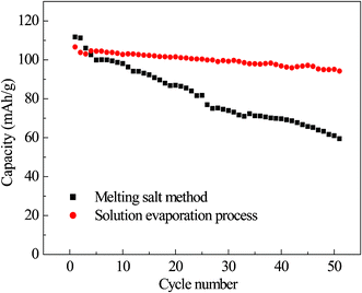
Fig. 6 shows the plot of capacity as a function of cycle numbers for the LiNi0.5Mn1.5O4 synthesized by different methods at 1 C rate between 3.0 and 4.9 V at 25 °C. It can be seen that the LiNi0.5Mn1.5O4 synthesized by the solution evaporation process shows a small diminution of discharge specific capacity during 50 cycles with good capacity retention, but the LiNi0.5Mn1.5O4 produced by the melting salt method shows a very severe capacity loss during 50 cycles, indicating that it exhibits poor capacity retention.
 | ||
| Fig. 6 Cycling performances of LiNi0.5Mn1.5O4 composites synthesized by different methods at 1 C. | ||
3.2 Effect of sintering temperature on performance of LiNi0.5Mn1.5O4 synthesized by the solution evaporation process
In this section, the effects of different sintering temperatures on the electrochemical performances of the LiNi0.5Mn1.5O4 composites synthesized by solution evaporation process are investigated. After the mixture was calcined at 400 °C for 4 h in an oxygen atmosphere to decompose nitrate and acetate, the precursor was sintered at 700 °C, 750 °C, 800 °C and 850 °C, respectively, for 6 h in an oxygen atmosphere to obtain the samples and then annealed at 600 °C for 2 h in an oxygen atmosphere to obtain the final products.Fig. 7 shows the XRD patterns of the LiNi0.5Mn1.5O4 materials sintered at different temperatures. Compared with the standard spinel LiNi0.5Mn1.5O4, every peak position is identical. It can be seen from XRD patterns that three crystal faces of (111), (311) and (400) have the better diffraction peak intensity and stronger sensitivity at different temperatures, which indicates that four materials have good crystallization degrees. The LiNi0.5Mn1.5O4 at a synthesis temperature of 800 °C has the sharper and higher diffraction peaks, indicating its better crystallinity. All of the materials display a spinel structure with a space group of Fd3m.
 | ||
| Fig. 7 XRD patterns of LiNi0.5Mn1.5O4 materials sintering at different temperatures. | ||
SEM images of the LiNi0.5Mn1.5O4 materials prepared at different temperatures are shown in Fig. 8. It can be seen that their particle size increases with increasing calcination temperature and their particle morphologies are evidently different. When the synthesis temperatures are 700 °C and 750 °C, the sample particles are obscure, their surface morphologies are irregular and the agglomeration is severe. The LiNi0.5Mn1.5O4 particles at 800 °C and 850 °C are well-distributed, smooth-surfaced, morphologically neat and have small grain size.
 | ||
| Fig. 8 SEM images of LiNi0.5Mn1.5O4 composites synthesized at different temperatures. | ||
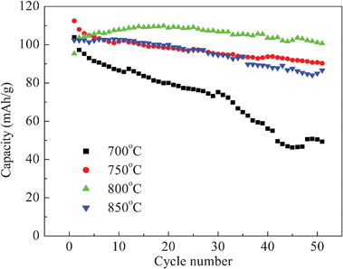
Fig. 9 shows the discharge capacities of the LiNi0.5Mn1.5O4 synthesized at different temperatures at 0.5 C for 50 cycles. The LiNi0.5Mn1.5O4 synthesized at 800 °C has the highest discharge capacity and also has a stable cycle performance and slow decay. The sample synthesized at 700 °C has the lowest capacity, which results from the fact that it does not form an intact crystal structure to increase the diffusion path of Li ion due to the lower sintering temperature.
 | ||
| Fig. 9 Cycling performances of LiNi0.5Mn1.5O4 for various synthesized temperatures at 0.5 C. | ||
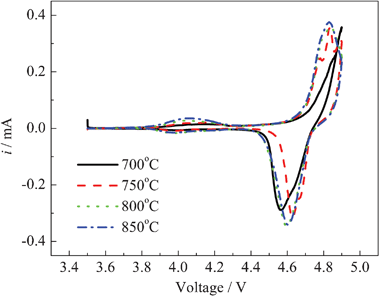
Fig. 10 shows the cyclic voltammograms (CV) of the LiNi0.5Mn1.5O4 at the various synthesized temperatures at 0.5 C after 50 cycles with a scanning rate of 0.05 mV s−1. It can be seen from Fig. 10 that the redox peaks of the LiNi0.5Mn1.5O4 are observed at around 4.7 V for the oxidation of Ni2+ to Ni4+. When the synthesis temperatures are 750 °C , 800 °C and 850 °C, there are the small redox peaks between 3.9 V and 4.2 V in their CV, which are attributed to the Mn3+/4+ redox. Their characteristics are consistent with the cubic spinel Fd3m structure of the LiNi0.5Mn1.5O4. The distance of redox peaks in CV curves may illustrate the stand or fall of the cycle reversibility of a material. The LiNi0.5Mn1.5O4 synthesized at 800 °C has the best cycle reversibility.
 | ||
| Fig. 10 Cyclic voltammograms of LiNi0.5Mn1.5O4 at various temperatures at 0.5 C after 50 cycles. | ||
Fig. 11 shows the twentieth charge–discharge curves of the LiNi0.5Mn1.5O4 synthesized at different temperatures at 0.5 C. The LiNi0.5Mn1.5O4 synthesized at 800 °C has the highest discharge capability and the longest plateau of 4.7 V. The materials synthesized at 750 °C, 800 °C and 850 °C have a small plateau of 4.1 V, indicating that they have the cubic spinel Fd3m structure. The material synthesized at 700 °C only has a 4.6 V plateau, which belongs to the cubic spinel P4332 structure. It is consistent with the results reported by Kim groups 17 that the cubic spinel Fd3m structure may form the primitive simple cubic P4332 at 700 °C. The LiNi0.5Mn1.5O4 composite with the space group of Fd3m shows better electrochemical behaviors than that with the cubic spinel P4332 structure.
 | ||
| Fig. 11 Twentieth charge–discharge curves of LiNi0.5Mn1.5O4 at the various synthesized temperatures at 0.5 C. | ||
4. Conclusions
LiNi0.5Mn1.5O4 as a 5 V cathode material for lithium-ion battery was synthesized through a solution evaporation process. The discharge capacity and cycle stability of the LiNi0.5Mn1.5O4 material synthesized through a solution evaporation process were superior to those obtained by the melting salt method. With the rising of the sintering temperature, the particle size of LiNi0.5Mn1.5O4 materials gradually increases, their crystallinity degrees enhance and their surface morphologies are gradually neatened. Electrochemical test results show that the LiNi0.5Mn1.5O4 prepared at 800 °C has the best cycle reversibility, the highest capacity and cycle stability.Acknowledgements
This research is financially supported by the National Natural Science Foundation of China (Grant No. 21273058), the Scientific Research Foundation for the Returned Overseas Chinese Scholars, State Education Ministry (2008) and Scientific Research Foundation for Returned Scholars of Heilongjiang Province of China (LC08C33).References
- S. V. Ivanova, E. Zhecheva, D. Nihtianova and R. Stoyanova, J. Mater. Sci., 2011, 46, 7098 CrossRef CAS.
- S. B. Park, W. S. Eom, W. I. Cho and H. Jang, J. Power Sources, 2006, 159, 679 CrossRef CAS.
- H. M. Wu, J. P. Tu, Y. F. Yuan, Y. Li and B. X. Zhao, Electrochim. Acta, 2005, 50, 4104 CrossRef CAS.
- Y. Shin and A. Manthiram, Electrochim. Acta, 2003, 48, 583 Search PubMed.
- S. H. Oh, K. Y. Chung, S. H. Jeon, C. S. Kim, W. I. Cho and B. W. Cho, J. Alloys Compd., 2009, 469, 244 CrossRef CAS.
- G. Q. Liu, L. Wen, G. Y. Liu and Y. W. Tian, J. Alloys Compd., 2010, 501, 233 CrossRef CAS.
- R. Santhanam and B. Rambabu, J. Power Sources, 2010, 195, 5442 CrossRef CAS.
- X. G. Wu and B. K. Seung, J. Power Sources, 2002, 109, 53 CrossRef CAS.
- T. Ohzuku, K. Ariyoshi and S. Yamamoto, J. Ceram. Soc. Jpn., 2002, 110, 501 CrossRef CAS.
- J. H. Kim, S. T. Myung and Y. K. Sun, Electrochim. Acta, 2004, 49, 219 CrossRef CAS.
- G. Q. Liu, Y. J. Wang and W. Li, Electrochim. Acta, 2005, 50, 1965 CrossRef CAS.
- Y. S. Lee, Y. K. Sun, S. Ota, T. Miyashita and M. Yoshio, Electrochem. Commun., 2002, 49, 89 Search PubMed.
- S. Myung, T. S. Komaba, N. Kumagai, H. Yashiro, H. T. Chung and T. H. Cho, Electrochim. Acta, 2002, 47, 2543 CrossRef CAS.
- S. H. Park, S. W. Oh, S. T. Myung, Y. C. Kang and Y. K. Sun, Solid State Ionics, 2005, 176, 481 CrossRef CAS.
- I. Yasushi, N. Hirosuke and K. Nobuyuki, J. Power Sources, 2003, 119, 125 CrossRef.
- J. H. Kima, S. T. Myung and Y. K. Sun, Electrochim. Acta, 2004, 49, 219 CrossRef.
- J. H. Kim, S. T. Myung, S. C. Yoon, S. G. Kang and K. Y. Sun, Chem. Mater., 2004, 16, 906 CrossRef CAS.
| This journal is © The Royal Society of Chemistry 2012 |
