Lithium–liquid battery: harvesting lithium from waste Li-ion batteries and discharging with water
Nina Mahootcheian
Asl
b,
Seong Shen
Cheah
c,
Jason
Salim
c and
Youngsik
Kim
*ab
aRichard Lugar Center for Renewable Energy, Indiana University Purdue University Indianapolis, United States. E-mail: yk35@iupui.edu
bDepartment of Mechanical Engineering, Indiana University Purdue University Indianapolis, United States
cDepartment of Electrical and Computer Engineering, Indiana University Purdue University Indianapolis, United States
First published on 8th June 2012
Abstract
This study demonstrates the feasibility of using water and the contents of waste Li-ion batteries for the electrodes in a Li–liquid battery system. Li metal was collected electrochemically from a waste Li-ion battery containing Li-ion source materials from the battery's anode, cathode, and electrolyte, thereby recycling the Li contained in the waste battery at room temperature. The harvested Li metal in the battery system was discharged to produce electricity by using water as the cathode. The discharge voltage of the water showed 2.7 V at 0.1 mA cm−2versus Li metal harvested from waste Li-ion batteries, compared to 2.8 V versus fresh Li metal at the same current rate. Since the electrodes for this proposed battery system are water and the contents of waste Li-ion batteries, the cost of the battery decreases, which is an attractive strategy for a large size energy storage application.
1. Introduction
The increased interest in using renewable energy such as solar and wind has prompted the need to find energy storage systems, to make such energy sources reliable. Many types of energy storage systems1–3 have been considered, such as pumped hydroelectric storage, compressed air energy storage (CAES), flywheels, and electrochemical storage. Depending on the application of the system, each storage design is more suitable either in efficiency, lifetime, discharge time, or in weight or mobility of the system. Among these various energy storage systems, electrochemical storage such as batteries has the advantage of being more efficient compared to pumped hydroelectric and CAES storage.3 A battery works by directly converting chemical energy to electrical energy by employing different chemistries. A varied combination of anode, cathode and electrolyte materials produces numerous types of batteries such as the Li-ion, lead–acid, Na–S, and vanadium redox batteries.Presently, the lithium (Li)-ion rechargeable battery is the most common type of battery used in consumer portable electronics due to its high energy density per weight or volume and its good recharge efficiency. However, the Li-ion battery for use in stationary energy storage applications is limited by cost and safety concerns. The cheapest rechargeable batteries are lead–acid batteries. Their efficiency is somewhere between 75–85% with a 15–25% loss of DC electric current from recharge to discharge.3,4 Sodium–sulfur (NaS) batteries are not well-known, but they have a high energy density and efficiency around 76%.3,5 However, NaS batteries are not feasible for portable electric devices because they do not come in smaller sizes and only operate efficiently at high temperatures. However, NaS batteries are economical and efficient for large installations. Another type of rechargeable battery for stationary energy storage applications is the flow battery. It stores electrolytes in tanks, therefore having a flexible energy capacity depending on how many electrolyte tanks one connects to the power input/output unit. The best known and widely applied flow battery is the vanadium redox battery (VRB).6
Even though the efficiency of the battery is relatively better than other types of energy storage devices, the current battery technology is still considered too expensive for stationary storage. For renewable energy to be stored without government subsidy, the storage process must be kept below $200 per kilowatt.7 Thus, to meet the increasing demand to store large amounts of electric energy for stationary applications, one must develop a viable battery technology that, as the battery increases in size, it decreases in cost per unit energy and amount of power stored.
Here, we propose the use of waste Li-ion batteries and water for both electrodes in a Li–liquid battery system. This study shows that the Li metal can be harvested from the waste Li-ion batteries, and the harvested Li metal can be discharged with the use of water as the cathode to produce electric energy. This concept can be extended to a Li–liquid flow battery for a large energy storage system (see Fig. 1) where the discharge and charge parts are separated (via multi-layer electrolyte) to allow for more choices of materials to efficiently store and produce the energy at a low cost. In the charging system, the Li metal is harvested by charging the cell and drawing from one of the following three sources: (a) using waste Li-ion battery materials containing Li ions such as the graphite anode LixC6, cathodes made of LixFePO4 or LixCoO2, or the organic liquid electrolyte, 1 M LiPF6 in EC:DEC, (b) using the discharged products such as LiOH (aq) created by discharging the battery, or (c) collecting Li from both sources simultaneously. Charging the cell using renewable energy sources such as wind and solar power, the renewable energies are stored by the formation of the Li metal. As for the discharging system, water and other liquid solutions containing aqueous or non-aqueous solvents can be used as cathodes with the harvested lithium metal as the anode.
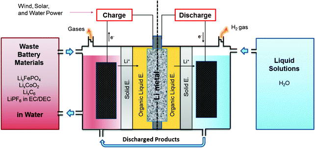 | ||
| Fig. 1 Schematic diagram of a Li–liquid battery system that uses waste battery materials and water as both electrodes. Li metal can be harvested electrochemically from a waste Li-ion battery containing Li-ion source materials from the battery's anode, cathode, and electrolyte. The harvested Li metal in the battery system can be discharged to produce electricity by using water as the cathode. With further development of other technologies including the solid electrolyte and overall system design, this concept of the battery system could possibly be used as a stationary energy storage device. If the system is charged from renewable energy sources, the renewable energy sources are stored by this formation of Li metal in the system. | ||
2. Experimental methods
2.1. Chemicals
A lithium ribbon (99.9%) of 0.38 mm thickness was purchased from Sigma Aldrich, and disks, each with a 0.8 cm diameter, were cut for use as the anode. 1 M LiPF6 in ethylene carbonate (EC)–dimethyl carbonate (DMC) (1![[thin space (1/6-em)]](https://www.rsc.org/images/entities/char_2009.gif) :
:![[thin space (1/6-em)]](https://www.rsc.org/images/entities/char_2009.gif) 1 volume ratio) was purchased from Novolyte Corp for use as an organic non-aqueous liquid electrolyte. As a solid electrolyte, the Li-ion-conducting glass ceramic plate, Li1+x+yTi2−xAlxP3−ySiyO12 (LTAP), measuring 1 inch × 1 inch with a 150 μm thickness and σLi ≈ 10−4 S cm−1 at room temperature, was purchased from OHARA, Inc. The solid electrode powders used in this study such as LiFePO4, and C6 were purchased from MTI Corporation. SUPER P carbon black (TIMCAL) was used as the electronic conductive powder for the solid and liquid electrodes. Carbon paper of 280 μm thickness purchased from Fuel Cell Store, Inc. was used as the current collector for liquid solutions.
1 volume ratio) was purchased from Novolyte Corp for use as an organic non-aqueous liquid electrolyte. As a solid electrolyte, the Li-ion-conducting glass ceramic plate, Li1+x+yTi2−xAlxP3−ySiyO12 (LTAP), measuring 1 inch × 1 inch with a 150 μm thickness and σLi ≈ 10−4 S cm−1 at room temperature, was purchased from OHARA, Inc. The solid electrode powders used in this study such as LiFePO4, and C6 were purchased from MTI Corporation. SUPER P carbon black (TIMCAL) was used as the electronic conductive powder for the solid and liquid electrodes. Carbon paper of 280 μm thickness purchased from Fuel Cell Store, Inc. was used as the current collector for liquid solutions.
2.2. Fabrication of the multilayer electrochemical cell
Fig. 2 shows a schematic diagram of the laboratory-sized battery cell that is designed for testing a small amount (≤ 5 mL) of liquids as cathodes. In order to prevent the two liquids from mixing, the open side of the polypropylene bar containing the Li metal anode and 1 M LiPF6 in EC–DMC liquid electrolyte is completely sealed from the cathode compartment by a dense ceramic solid electrolyte. The solid electrolyte plate was first placed on the top of the anode part of the cell and sealed by epoxy. The sealing of the anode part by the solid electrolyte must be done carefully to protect the Li metal from exposure to a highly oxidizing cathode environment. Otherwise, proper data cannot be obtained from the samples being investigated.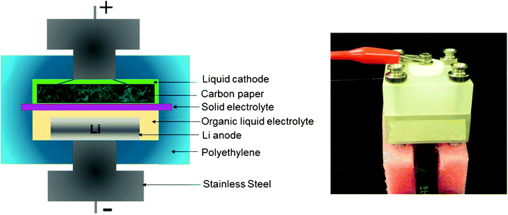 | ||
| Fig. 2 This figure is a schematic diagram of the cell designed for testing a liquid as the cathode with Li metal as the anode. The image shows the fully assembled cell under test. | ||
Then, the sealed anode part was placed in an argon filled glove box where the water and oxygen concentrations were maintained at less than 4 ppm. The Li metal disk and a non-aqueous electrolyte, 1 M LiPF6 in EC–DMC, were loaded into the anode part inside the glove box. After assembling the anode part, the assemblage was moved out of the glove box. The liquid cathode was poured into the cathode part of the cell. Then, the carbon paper, to be used as the current collector, was placed over the liquid. The assembled battery cell was then connected to the testing station. A Solartron 1470 cell tester was used to perform the charge and discharge tests.
2.3. Assembly of the coin cell
The electrodes for the coin cell were fabricated from a 70![[thin space (1/6-em)]](https://www.rsc.org/images/entities/char_2009.gif) :
:![[thin space (1/6-em)]](https://www.rsc.org/images/entities/char_2009.gif) 20
20![[thin space (1/6-em)]](https://www.rsc.org/images/entities/char_2009.gif) :
:![[thin space (1/6-em)]](https://www.rsc.org/images/entities/char_2009.gif) 10 (wt%) mixture of active material, Super P carbon (Cnergy) as the current conductor, and polytetrafluoroethylene (G-580, ICI) as the binder. The active material and conductor were mixed completely, and then the polytetrafluoroethylene was added in, and all three were mixed together. The mixture was rolled into thin sheets and punched into 7 mm-diameter circular disks as electrodes. The typical electrode mass and thickness were 5–10 mg and 0.03–0.08 mm. The electrochemical cells were prepared in a standard 2016 coin-cell hardware with lithium metal foil used as both the counter and reference electrodes. The electrode disks and cells were prepared in an argon glove box along with the electrolyte used for analysis, 1 M LiPF6 in a 1
10 (wt%) mixture of active material, Super P carbon (Cnergy) as the current conductor, and polytetrafluoroethylene (G-580, ICI) as the binder. The active material and conductor were mixed completely, and then the polytetrafluoroethylene was added in, and all three were mixed together. The mixture was rolled into thin sheets and punched into 7 mm-diameter circular disks as electrodes. The typical electrode mass and thickness were 5–10 mg and 0.03–0.08 mm. The electrochemical cells were prepared in a standard 2016 coin-cell hardware with lithium metal foil used as both the counter and reference electrodes. The electrode disks and cells were prepared in an argon glove box along with the electrolyte used for analysis, 1 M LiPF6 in a 1![[thin space (1/6-em)]](https://www.rsc.org/images/entities/char_2009.gif) :
:![[thin space (1/6-em)]](https://www.rsc.org/images/entities/char_2009.gif) 1 EC–DMC. A Solartron 1470 cell tester was used to perform the charge and discharge tests.
1 EC–DMC. A Solartron 1470 cell tester was used to perform the charge and discharge tests.
3. Results and discussion
3.1. Multilayer electrolyte strategy
The key strategy in this research lies in the use of a multi-layer electrolyte. The multi-layer electrolyte consists of one liquid electrolyte and one solid electrolyte as shown in Fig. 3. The organic, liquid electrolyte is used because, as a liquid, it creates close physical contact with the solid lithium anode. Although the lithium metal reduces the 1 M LiPF6 in EC–DMC liquid electrolyte by direct contact, the formation of a solid electrolyte interface (SEI) layer on the surface of the Li metal allows Li to be used as the anode with the organic liquid electrolyte. The solid electrolyte is an inorganic solid that separates the two liquids (liquid electrolyte and liquid cathode), and prevents mixing of the liquids while also making it possible to use a cathode in all three phases (solid, liquid, and gas). The solid electrolyte, Li1+x+yTi2−xAlxP3−ySiyO12 (from OHARA), is commercially available with an area of 1 inch × 1 inch, 150 μm thickness, and σLi ≈ 10−4 S cm−1 at room temperature. The relatively low Li-ion conductivity of the solid electrolyte can limit the electrochemical performance of the liquid cathodes when a high current discharge or charge is applied. Hence, in this experiment, a low current rate of 0.1 mA cm−2 was applied to minimize the effect of the cell resistance on the voltage of materials being investigated.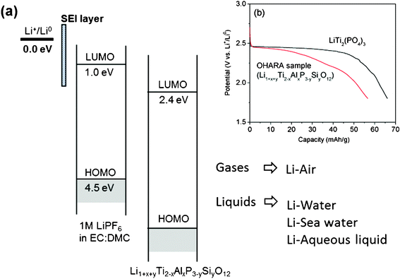 | ||
| Fig. 3 This figure represents electrochemical potentials of the multi-layer electrolyte of 1 M LiPF6 in EC:DMC/Li1+x+yTi2−xAlxP3−ySiyO12. With this electrolyte strategy, the air and liquid phases such as water, sea water, and other liquid solutions can be selected as the cathodes. SEI layer: Solid Electrolyte Interface layer. LUMO: Lowest Unoccupied Molecular Orbital. HOMO: Highest Occupied Molecular Orbital. The inserted Fig. 3(b) shows the discharge voltages of the solid electrolytes vs. Li+/Li0 corresponding to 2.4 eV of the LUMO. | ||
The Li1+x+yTi2−xAlxP3−ySiyO12 solid electrolyte is not stable at a low voltage range because the Ti4+ in its structure can be reduced to Ti3+ at 2.4 V versus Li+/Li0 by accepting electrons from the current collector. Fig. 3(b) shows that the discharge voltage curve of the Li insertion into the Li1+x+yTi2−xAlxP3−ySiyO12 sample was observed at 2.4 V vs. Li+/Li0 at a rate of 0.05 mA cm−2, where it is compared to the discharge voltage curve of the LiTi2(PO4)3 sample. The voltage relative to Li metal of Li intercalation solid compounds corresponds to the energy relative to Li+/Li0 of the redox couple energy of a transition-metal cation.8 Hence, it is believed that the energy band of the Ti4+/Ti3+ redox couple in the Li1+x+yTi2−xAlxP3−ySiyO12 sample is located at 2.4 eV below the Fermi energy EF of Li metal, which also corresponds to the Lowest Unoccupied Molecular Orbital (LUMO) of the solid electrolyte as shown in Fig. 3(b). However, the use of a polyanion (PO4)3− in place of an oxide ion in the phosphate materials can lower the top of the O–2p bands to below 5.0 eV below EF of Li0,8 which corresponds to the Highest Occupied Molecular Orbital (HOMO) of the solid electrolyte.
By using a solid electrolyte with a lower HOMO in the cathode side, there is greater flexibility in choosing cathodes that produce voltages above 4.5 V. This will be an improvement over the small electrochemical window of liquid electrolytes, which are presently used and cannot produce a range beyond 1.0–4.5 V vs. Li+/Li0. In addition, when the anode part of the cell composed of Li metal and the organic liquid electrolyte are completely separated and sealed by the dense solid electrolyte-only providing Li-ion mobility,9,10 the choices for cathode will be dramatically widened to include solid, liquid, and gas phases. Applying this concept, solid and liquid phases as well as gas phases have been used as cathodes to create different battery systems such as the Li–Ni,11 Li–liquid,10,12–16 and Li–air10,17–19 batteries. Based on these reports, we hypothesized that, by charging the cell, Li metal could be electrochemically collected from any material containing Li-ions. This idea extended to harvesting Li metal from waste Li-ion batteries, in both solid and liquid phases, that contain Li-ion sources such as the LixC6 anode, LixFePO4 cathode, and LiPF6 in the EC–DEC electrolyte. The harvested Li metal could then be an anode Li–liquid flow batteries by using water as the cathode.
3.2. Li metal harvesting from Li solid and liquid phases in water
Experiments were performed during the charging of the cell to test whether Li-ions could be extracted from lithium solid and liquid phase compounds that were placed in water. Water was selected as a liquid matrix in which the lithium phases were placed (or dissolved) and delivered into the charge section of the proposed Li–liquid flow battery system (see Fig. 1). Water was a good choice in this experiment because it is a non-pollutant and inexpensive in most areas.Solid cathode particles of the LiFePO4 were mixed with carbon black powder, and the mixture was placed in water and ultrasonicated for one hour to produce a homogenous mixture with the water. Then, the liquid solution was placed on the carbon paper in the cathode part where the carbon paper absorbed the solution and used it as the current collector. In the anode side, there was no Li metal attached at the initial state of the cell. This means that stainless steel (SS) was used as a negative electrode at the initial state. Fig. 4 shows the charge curve of LiFePO4, which was placed in water and mixed with super P powders.
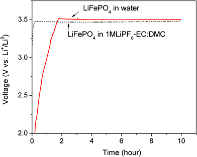 | ||
| Fig. 4 Charge voltage curve of the LiFePO4 in pure DI water and compared with the charge voltage curve of the LiFePO4 tested in the coin cell where the Li metal anode and the organic liquid electrolyte, 1 M LiPF6 in EC–DMC are used. They are measured at the current rate of 0.1 mA cm−2. | ||
The open circuit voltage was observed to be around 0.4 V vs. stainless steel (SS) electrode for the LiFePO4. When the cell began to charge at 0.1 mA cm−2, the slope curve was observed to start around 0.4–3.5 V. This slope could be a result of the activation polarization that arises from kinetics hindrances of the charge-transfer reaction taking place at the cathode–electrolyte interface (Li-ions leaving from the cathode particles) and the anode–electrolyte interface (Li forming on the SS electrode). At 3.50 V, after the slope curve, a flat charge voltage appears for the LiFePO4 cathode, which corresponds to the Li extraction from the Li1−xFePO4. This flat voltage is similar in voltage range to that (3.47 V) of the LiFePO4 measured in the coin cell with a Li metal anode and an organic liquid electrolyte, 1 M LiPF6 in EC–DMC, as shown in Fig. 4. This result indicates that the charge voltage curve of the cathode particle is not affected by the use of the solid electrolyte when a low current rate of the 0.1 mA cm−2 is applied. The Li extraction from the LiFePO4 particles in aqueous electrolytes was reported in the literature,20 but LiTi2(PO4)3 was used as the anode for the LiFePO4 cathode due to the small electrochemical window of aqueous electrolytes.
Graphite (C6) is the most common anode for present Li-ion batteries. When a waste Li-ion battery contains a lithiated graphite (LixC6) anode, it would be another potential Li-ion source for the Li metal harvesting system. LixC6 is prepared by electrochemical insertion of Li-ions into the C6 inside the coin cell that uses Li metal as the negative electrode. Fig. 5(a) shows the typical discharge and charge curves of the graphite versus Li metal electrode. When the graphite is fully discharged, it becomes LiC6. After disassembling the cell, the LiC6 powder (0.016 mg) is collected and transferred into the water (1.9 g). An aggressive exothermal reaction with the production of gas is observed, similar to that of Li metal in water (see eqn (2). Because the Fermi energy of the LiC6 is only 0.2 eV below the Fermi energy of Li metal,8 the LiC6 is also a very reducing agent. This means that the LiC6 would decompose H2O and subsequently form LiOH when it is added to water. After the addition of the LiC6 into the pure DI water, the pH increases to ∼12 from 7, which indicates that the pure DI water becomes a strong alkali aqueous solution due to the formation of the LiOH. This reaction is also supported by the literature,21 which reports that LiOH forms on the surface of the LiC6 anode by adding H2O into the LiClO4 in PC electrolyte in the battery cell.
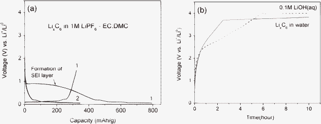 | ||
| Fig. 5 (a) Discharge and charge voltage curves of the LixC6 in 1 M LiPF6 in EC–DMC and (b) charge voltage curves of LixC6 in the pure DI water and compared with that of 0.1 M LiOH (aq). They are measured at a current rate of 0.1 mA cm−2. | ||
Fig. 5(b) shows the charge voltage curve of the LiC6 placed in water. The flat voltage curve is observed at 3.8 V. This corresponds to the Li extraction from LiOH (aq) formed by the reaction of LixC6 with water. To support this hypothesis, a 0.1 M LiOH aqueous liquid solution was prepared and charged at the same experimental condition as shown in Fig. 5(b). The flat charge voltage curve appeared at 4.0 V with the chemical reaction below.
| 4LiOH (aq) → 4Li (s) + 2H2O (l) + O2 (g) | (1) |
This is similar to what was observed (3.8 V) when the LiC6 was placed in water. The slight voltage difference could be due to the difference of the LiOH mole concentration or chemical compounds formed in the liquid solution, which could affect Li-ion and electron conductivity of the liquid matrix.
In addition to the anode and cathode materials, electrolytes could be another Li-ion source for the Li metal harvesting system. Li-ions can be collected from a pure organic liquid electrolyte by charging the cell at voltages higher than 4.5 V vs. Li+/Li0. The oxidation voltage of the pure organic liquid electrolytes was reported at >4.5 V vs. Li+/Li0 in the literature.22 Our measurement (Fig. 6) also shows that pure liquid electrolyte 1 M LiPF6 in EC–DMC is oxidized at 5.3 V vs. Li+/Li0 at the current rate of 0.1 mA cm−2, where Li-ions are transferred into the anode side and form Li metal. Interestingly, when the organic liquid electrolyte 1 M LiPF6 in EC–DMC was mixed with water in a volume ratio of 1![[thin space (1/6-em)]](https://www.rsc.org/images/entities/char_2009.gif) :
:![[thin space (1/6-em)]](https://www.rsc.org/images/entities/char_2009.gif) 1, the charge voltage curve was observed at about 3.7 V vs. Li+/Li0 at 0.1 mA cm−2, as shown in Fig. 6. This charge voltage is significantly lower than 5.3 V of the pure liquid electrolyte. Since the redox reaction in the liquid solution is affected by the chemistry of solvents and salts,23 the new chemical compounds formed by the reaction of the liquid electrolyte with water would be responsible for the low charge voltage of 3.7 V.
1, the charge voltage curve was observed at about 3.7 V vs. Li+/Li0 at 0.1 mA cm−2, as shown in Fig. 6. This charge voltage is significantly lower than 5.3 V of the pure liquid electrolyte. Since the redox reaction in the liquid solution is affected by the chemistry of solvents and salts,23 the new chemical compounds formed by the reaction of the liquid electrolyte with water would be responsible for the low charge voltage of 3.7 V.
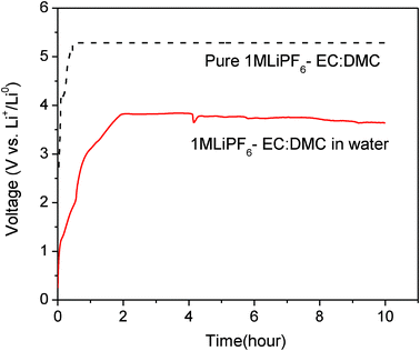 | ||
| Fig. 6 Charge voltage curves of 1 M LiPF6-EC–DMC in the pure DI water and compared with that of the pure 1 M LiPF6-EC–DMC. They are measured at the current rate of 0.1 mA cm−2. | ||
Indeed, the reaction of the LiPF6 organic electrolyte with water has been intensively investigated24–26 because water content in the liquid electrolyte is detrimental to the Li-ion battery. However, it is impossible to completely eliminate water from the liquid electrolyte. The mechanism for the reaction between the organic LiPF6 liquid electrolyte and water is very complex and has not been clearly identified yet. This reaction was reported to occur with the formation of many chemicals compounds such as LiF, HF, PF5, POF3, POF2(OH), and LiOH.24–26 In addition, the degree of electrolytic dissociation must be considered during the reaction between the LiPF6 liquid electrolyte and water.26 It would be challenging to identify the precise Li extraction mechanism of the mixed liquid solution (water + non-aqueous liquid electrolyte) that corresponds to the charged voltage of 3.7 V observed in this experiment at this moment.
Due to the low oxidation voltage of organic liquid electrolytes with moisture content, tremendous efforts have been made in research laboratories and battery companies to keep the organic liquid electrolyte in a water free atmosphere. In contrast, this low oxidation voltage of the mixed liquid or water contaminated organic liquid electrolyte will be an advantage for the Li metal harvesting system because less energy is needed to collect Li metal from the liquid electrolytes that undergo changes in their chemical compositions and phases in the presence of water.
3.3. Li harvesting from waste Li-ion batteries
We tested the harvesting of Li metal from waste Li-ion batteries by attempting to collect Li metal from a Li-ion battery that uses the graphite anode, LiFePO4 cathode, and organic liquid electrolytes. The Li-ion battery was disassembled. Then, the whole disassembled battery including the anode, cathode, polymer separator, and organic liquid electrolytes were placed in water and stirred or ultrasonicated to collect electrode powders and electrolytes containing Li-ions. After removing the current collector and separator, only the liquid solution containing electrode powders and the liquid electrolyte remained, as shown in Fig. 7(a). That liquid solution was then placed on carbon paper in the cathode part (see Fig. 2) and charged with a bare stainless steel (SS) electrode (instead of using a Li metal electrode). Fig. 7(b) shows the charge voltage curves of the liquid solution containing all of the LixC6, LixFePO4, and organic liquid electrolyte at once. Li metal was observed on the surface of the SS electrode as shown in Fig. 7(c) after disassembling the cell. The aggressive reaction producing exothermal heat was observed when the SS electrode was placed in the water, which is another confirmation of the formation of Li metal.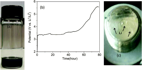 | ||
| Fig. 7 (a) Waste Li-ion battery materials in water, including LixC6, LixFePO4, and LiPF6 in EC–DEC. (b) Charge voltage curve at 0.1 mA cm−2 of the liquid solution shown in (a). (c) Li metal observed on the surface of a stainless steel (SS) electrode; the bare SS electrode was used before charging the battery. | ||
Also confirming the formation of Li metal on the SS electrode, the charged cell (which collected Li metal from waste battery materials) was discharged when pure DI water was used as the cathode. Fig. 8 shows the discharge voltage curve of the pure DI water versus Li metal harvested from the waste batteries. The mean discharge voltage appears to be about 2.7 V vs. Li+/Li0 at 0.1 mA cm−2, which is similar to the voltage found when fresh Li metal was used in the cell. The following chemical reaction occurs during discharge of the Li–water cell.27
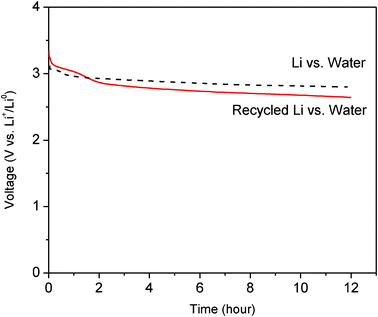 | ||
| Fig. 8 Discharge voltage curves at 0.1 mA cm−2 when using a cathode of pure DI water and an anode of Li metal harvested from waste Li-ion batteries, compared to the discharge voltage curve when using an anode of fresh Li metal. | ||
| 2Li (s) + 2H2O (l) → 2LiOH (aq) + H2 (g) | (2) |
The electrochemical performance of the Li–liquid flow battery including discharge–charge voltage, voltage efficiency, and rate capability could be improved by increasing the electronic and Li-ion conductivities of the liquid solutions. As an electronic conductive powder, Super P carbon black (TIMCAL Ltd.), with 62 m2 g−1 of the specific BET surface area, was used in this experiment, but other carbon powders with different sizes and physical properties will be tested in the future. Since functionalized carbon powders are reported to have a good dispersion character in water,30 this approach may improve the charge efficiency of the battery by providing better electronic conductivity between waste materials in water. Li-ion conductivity in the liquid solution could also be improved by adding lithium salts such as LiNO3, LiClO4, and Li2SO4. The addition of more waste organic liquid electrolyte may be another good strategy for improving the Li-ion conductivity in the liquid solution because it contains lithium salts such as LiPF6 or LiBF4.
4. Conclusion
The purpose of this study was to demonstrate the feasibility of developing a Li–liquid battery system that uses waste Li-ion batteries as a source of Li metal and that discharges with water, producing electricity. The use of the multilayer electrolyte strategy in this battery system made it possible to collect Li metal electrochemically from Li solid and liquid phases found in waste Li-ion batteries. This study further demonstrated that the harvested Li metal from waste Li-ion batteries could be used to form the anode in the battery system, producing 2.7 V at 0.1 mA cm−2 when water was used as the cathode.Although this study is in its early stages, the concept of using waste Li-ion batteries and water for the electrodes in a battery system is attractive for a large size energy storage application because it dramatically decreases the cost of electrode materials. With further development of the other parts of the system including the solid electrolyte, current collector, and overall system design, the Li–liquid flow battery system is a promising strategy for stationary energy storage of renewable energy sources.
Acknowledgements
This work was supported by the Research Support Funds Grant (RSFG) at Indiana University Purdue University Indianapolis (IUPUI). S. S. Cheah and J. Salim thank the Multidisciplinary Undergraduate Research Institute (MURI) program at IUPUI for financial support.References
- A. L. Robinson, Science, 1974, 184, 785 CAS.
- H. Ibrahim, A. Ilinca and J. Perron, Renewable Sustainable Energy Rev., 2008, 12, 1221 CrossRef CAS.
- H. Chen, T. N. Cong, W. Yang, C. Tan, Y. Li and Y. Ding, Prog. Nat. Sci., 2009, 19, 291 CrossRef CAS.
- C. Sandberg, Altairnano Charging the Energy Revolution, IBM Almaden Conference Lithium-ion Battery–Truth in Advertising, 2009 Search PubMed.
- R. Okuyama and E. Nomura, J. Power Sources, 1999, 77, 164 CrossRef CAS.
- L. Li, S. Kim, W. Wang, M. Vijayakumar, Z. Nie, B. Chen, J. Zhang, G. Xia, J. Hu, G. Graff, J. Liu and Z. Yang, Adv. Energy Mater., 2011, 1, 306 CrossRef.
- R. Crowe, Energy Storage Industry Grows To Integrate Wind, Solar, 2011 Search PubMed.
- J. B. Goodenough and Y. Kim, Chem. Mater., 2010, 22, 587 CrossRef CAS.
- I. Kowalczk, J. Read and M. Salomon, Pure Appl. Chem., 2007, 79, 851 CrossRef CAS.
- S. J. Visco, Y. S. Nimon, L. C. De Jonghe, B. D. Katz and A. Petrov, U.S. Patent 0037058, 2007 Search PubMed.
- H. Li, Y. Wang, H. Na, H. Liu and H. Zhou, J. Am. Chem. Soc., 2009, 131, 15098 CrossRef CAS.
- Y. Wang and H. Zhou, Electrochem. Commun., 2009, 11, 1834 CrossRef CAS.
- Y. Wang, H. Li, P. He and H. Zhou, ChemSusChem, 2010, 3, 571 CrossRef CAS.
- Y. Lu, J. B. Goodenough and Y. Kim, J. Am. Chem. Soc., 2011, 133, 5756 CrossRef CAS.
- Y. Wang, Y. Wang and H. Zhou, ChemSusChem, 2011, 4, 1087 CrossRef CAS.
- Y. Lu and J. B. Goodenough, J. Mater. Chem., 2011, 21, 10113 RSC.
- T. Zhang, N. Imanishi, Y. Shimonishe, A. Hirano, J. Xie, Y. Takeda, O. Yamamoto and N. Sammes, J. Electrochem. Soc., 2010, 157, A214 CrossRef CAS.
- T. Zhang, N. Imanishi, Y. Takeda and O. Yamamoto, Chem. Lett., 2011, 40, 668 CrossRef CAS.
- L. Li, X. Zhao and A. Manthiram, Electrochem. Commun., 2012, 14, 78 CrossRef CAS.
- X. Liu, T. Saito, T. Doi, S. Okada and J. Yamaki, J. Power Sources, 2009, 189, 706 CrossRef CAS.
- K. Kanamura, S. Shiraishi, H. Takezawa and Z. Takehara, Chem. Mater., 1997, 9, 1797 CrossRef CAS.
- K. Xu, Chem. Rev., 2004, 104, 4303 CrossRef CAS.
- K. Izutsu, Electrochemistry in Nonaqueous Solutions, WILEY-VCH, 2009, p. 89 Search PubMed.
- U. Heider, R. Oesten and M. Jungnitz, J. Power Sources, 1999, 81–82, 119 CrossRef CAS.
- D. Aurbach, A. Zaban, Y. Ein-Eli, I. Weissman, O. Chusid, B. Markovsky, M. Levi, E. Levi, A. Schechter and E. Granot, J. Power Sources, 1997, 68, 91 CrossRef CAS.
- T. Kawamura, S. Okada and J. Yamaki, J. Power Sources, 2006, 156, 547 CrossRef CAS.
- M. Urquidi-Macdonald, J. Flores, D. D. Macdonald, O. Pensado-Rodriguez and D. Vanvoorhis, Electrochim. Acta, 1998, 43, 3069 CrossRef CAS.
- T. Zhang, N. Imanishi, S. Hasegawa, A. Hirano, J. Xie, Y. Takeda, O. Yamamoto and N. Sammes, J. Electrochem. Soc., 2008, 155, A965 CrossRef CAS.
- S. Hasegawa, N. Imanishi, T. Zhang, J. Xie, A. Hirano, Y. Takeda and O. Yamamoto, J. Power Sources, 2009, 189, 371 CrossRef CAS.
- M. Weissmann, S. Baranton, J. Clacens and C. Coutanceau, Carbon, 2010, 48, 2755 CrossRef CAS.
| This journal is © The Royal Society of Chemistry 2012 |
