DOI:
10.1039/C2RA20554H
(Paper)
RSC Adv., 2012,
2, 7549-7556
Collapse and Stability of functionalized Carbon Nanotubes on Fe (1 0 0) Surface†
Received
27th March 2012
, Accepted 9th June 2012
First published on 13th June 2012
Abstract
The collapse and stability of carbon nanotubes (CNTs) functionalized by corrosion inhibitor molecules on the Fe (1 0 0) surface were studied using molecular mechanics and molecular dynamics simulations. The results show that the pristine CNTs can approach and even collapse spontaneously onto the Fe surface due to the van der Waals force between them when the CNT diameter exceeds a certain threshold. To avoid collapse of the CNTs, they are randomly side-functionalized by three corrosion inhibitors. When the modification coverage exceeds 4.33%, these modified CNTs can basically maintain their cylindrical structures on the Fe surface. The CNTs, randomly modified by appropriate inhibitor groups, can maintain their cylindrical structure stably, giving them the potential to be used as nanocontainers for maintaining or transporting molecules, etc. Moreover, our findings have great practical significance, and CNTs modified by the organic inhibitor groups can be considered to be environmentally-friendly corrosion inhibitors, which can provide some guidance towards understanding corrosion resistance of CNT-inhibitor composites.
I Introduction
Carbon nanotubes (CNTs), discovered by Iijima in 1991,1 have attracted great research interest, due to their unique properties, such as high electrical and thermal conductivity, excellent stiffness against bending, and high tensile strength.2 Using CNTs as nanofibers to enhance the mechanical,3–7 electrical,8–11 thermal,12,13 and optical14 properties of composite materials has been pursued extensively both in experimental and theoretical studies. However, the CNTs’ excellent properties can be affected by their deformation and collapse, which have been observed in experimental and theoretical work.15–24 In addition, carbon nanotubes are generally discussed in terms of the idealized geometry of free nanotubes, unperturbed by interaction with the environment. Experimental studies, however, are mostly performed using nanotubes that are dispersed on a surface with which they therefore interact. People find that the CNTs can deform when they come into contact with some metallic oxides, for example Cu2O.25 The collapsed CNTs appear as linked graphene ribbons and have the largest area to interact with the oxide substrate, which greatly enhances the adhesion between the CNTs and the oxide surface and keeps the system much more stable. CNTs collapsed on the surface have potential applications in corrosion protection and scale inhibition fields. But the deformation and collapse of CNTs are sometimes considered to change their original properties and restrict their practical applications for hydrogen storage,26,27 as nanocontainers,28–30 and for molecule transport,31–33 because the pristine cylindrical structures have been destroyed. Therefore, avoiding CNT deformation and collapse in CNT-based composites or on a surface remains a major challenge.
Chemical modification of CNTs is a possible strategy to improve the dispersion and stability of CNTs in CNT-based composites.34 Georgakilas et al. found that CNTs were functionalized with phenol groups, providing stable dispersions in a range of polar solvents, including water. Additionally, the functionalized CNTs could easily be combined with polymers and layered aluminosilicate clay minerals to give homogeneous, coherent, transparent CNT thin films and gels.34 Extensive experimental studies on CNTs modified with poly(vinyl alcohol) (PVA) or poly(acrylic acid) (PAA) are also present in the literature.35–43 Lin et al. studied the single-walled and multiple-walled CNTs functionalized with PVA in esterification reactions.35
They found that the PVA–CNT composite films are of high optical quality, without any observable phase separation, and the CNTs in the films are as well-dispersed as in solution.35 Therefore, chemical modification not only improves the functionality of CNT-based composites, but also the CNT stability in CNT-based composites.
Based on the above analysis, in this paper, using molecular mechanics (MM) and molecular dynamics (MD) simulations, three kinds of organic inhibitor groups are attached onto CNTs randomly to study the stability of the functionalized CNTs on the Fe surface. Previously, our group has used the chemical modification method to avoid CNT collapse on an Al surface by MD simulations.44 It demonstrated the influence of polar functional groups on the collapse of CNTs. Herein, we will focus on the influence of the organic inhibitor groups on the collapse of CNTs on the Fe surface. On the one hand, CNTs randomly modified by appropriate organic inhibitor groups can maintain their cylindrical structures, having the potential to be used as nanocontainers for maintaining or transporting molecules, etc. On the other hand, our findings have great practical significance, and CNTs modified by the organic inhibitor groups can be considered to be environmentally-friendly corrosion inhibitors, which can provide some guidance towards understanding corrosion resistance of CNT-inhibitor composites.
II Experimental section
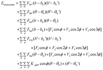
MM and MD simulations were conducted to explore the interfacial interaction between the CNTs modified by corrosion inhibitor molecules and the Fe (1 0 0) surface. Here, MM and MD simulations were carried out using a commercial software package called Materials Studio developed by Accelrys Inc. MM and MD are implemented by the Discover code in Materials Studio software. The interatomic interactions are described by the force field of condensed phased optimized molecular potential for atomistic simulation studies (COMPASS).45 This is the first ab initio force field that is parametrized and validated using condensed-phase properties in addition to various ab initio and empirical data, and it has been proven to be applicable in describing the mechanical properties of CNTs.46,47 The dynamics process is conducted to allow the system to exchange heat with the environment at a constant temperature. The Andersen method48 is employed in the thermostat to control the thermodynamic temperature, which is kept constant by allowing the simulated system to exchange energy with a “heat bath”, and generate the correct statistical ensemble. The force field is expressed as a sum of valence (or bond), cross-terms, and non-bond interactions:| | | Etotal = Evalence + Ecross-term + Enon-bond | (1) |
| |  | (2) |
| |  | (3) |
| |  | (4) |
The valence energy, Evalence, is generally accounted for by terms including bond stretching, valence angle bending, dihedral angle torsion, and inversion. The cross-term interaction energy, Ecross-term, accounts for factors such as bond or angle distortions caused by nearby atoms to accurately reproduce the dynamic properties of molecules. The non-bond interaction term, Enon-bond, accounting for the interactions between non-bonded atoms, is primarily accounted for by the van der Waals (vdW) interaction effect. Here, q is the atomic charge, ε is the dielectric constant, and rij is the i–j atomic separation distance. b and b′ are the lengths of the two adjacent bonds, θ is the two-bond angle, ϕ is the dihedral torsion angle, and x is the out of plane angle. b0, ki (i = 2–4), θ0, Hi (i = 2–4), ϕ0i (i = 1–3), Vi (i = 1–3), Fbb′, b0′, Fθθ′, θ0′, Fbθ, Fbϕ, Fb′θ, Fi (i = 1–3), Fθϕ, Kϕθθ′, Aij, and Bij are fitted from quantum mechanics calculations and implemented into the Discover module of Materials Studio.
Three kinds of corrosion inhibitors are chosen in this study due to their simplicity and generic representation features, and they are benzimidazole, PVA and PAA. The molecular models of benzimidazole, PVA and PAA are shown in Fig. 1; the bonded SWNT atoms protrude away from the CNT axes and the hybridization changes from sp2 to sp3.49 As indicated by Haremza et al.,50 sidewall functionalization disrupts the π-bonding symmetry of the sp2 hybridization and compromises the unique electronic properties of the CNTs. The CNT (10, 10), with diameter 13.56 Å and length 36.89 Å, was selected for the simulation of the CNT–Fe (1 0 0) system. The unsaturated boundary effect was avoided by adding hydrogen atoms at the ends of the CNTs. Each C–C bond length was 1.42 Å and the C–H bond length was 1.14 Å. The hydrogen atoms had charges of +0.1268 e and the carbon atoms connecting hydrogen atoms had charges of −0.1268 e, thus the neutrally charged CNTs were constructed. The designed system consisted of an Fe (1 0 0) lattice plane with a thickness of 15.77 Å, which was constructed as a supercell of 57.33 × 57.33 × 75.77 Å3.
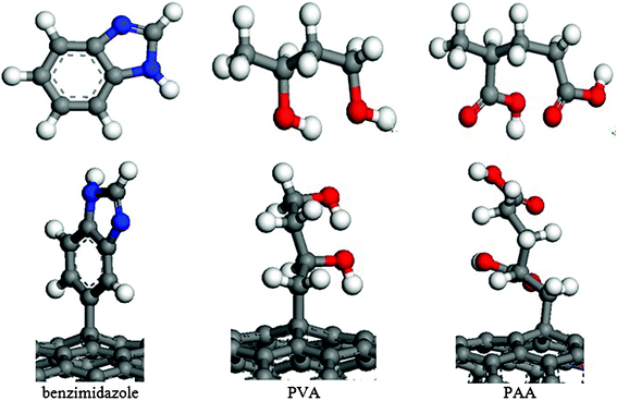 |
| | Fig. 1 Molecular models of benzimidazole, PVA, PAA and the CNTs connected with these groups (the blue spheres represent ammonia atoms, the red spheres represent oxygen atoms, the ashy spheres represent carbon atoms and the white spheres represent hydrogen atoms). | |
CNTs with 1.0%, 1.33%, 2.0%, 2.67%, 3.33%, 4.0%, 4.33%, 4.67% of the carbon atoms randomly functionalized were simulated. Fig. 2 shows a snapshot of CNT (10, 10) with benzimidazole groups randomly chemisorbed onto 1.0% of the carbon atoms. For the pristine CNT–Fe (1 0 0) system, as an initial configuration, the CNT was parallel to the Fe (1 0 0) plane, which was separated by 7 Å plus the radius size of the CNT, and the Fe (1 0 0) surface was parallel to the x–y plane. The cut-off distance was 9.5 Å and the permittivity of free space in the complex was six, which was similar to the electrical double layer in solution. The models were put into an NVT ensemble simulation with a temperature of 300 K for 100 ps. For the randomly functionalized CNT–Fe (1 0 0) system, the initial separation distance was 9 Å, due to the large molecule functionalization, and the simulation time was 500 ps. All MM simulations were performed to find the thermal stable morphology, and achieved the conformation with the minimum potential energy for the simulation system; all MD simulations were performed in the NVT ensemble. When H atoms are present in the system, a smaller time step (<1 fs) should be used.51 We investigate the accuracy of the calculation with time steps of 0.4 and 1 fs. The results show that the bonding strengths of the system simulated at time steps of 0.4 and 1 fs are basically identical. The error in the binding energy is about 0.6%. Therefore, a fixed step time of 1 fs was used in all cases to save the simulation time. Then the full-precision trajectory was recorded and the results were analyzed.
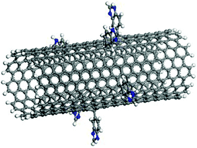 |
| | Fig. 2 Illustration of a CNT (10, 10) with benzimidazole groups randomly chemisorbed onto 1.0% of the carbon atoms. | |
III Results and discussion
The bonding strength between the CNTs and the Fe surface can be evaluated by the interfacial energy between them. Generally, the interaction energy is estimated from the difference between the potential energy of the composite system and the potential energy for the Fe surface and the corresponding CNTs as follows:52–55| | | Einteraction = Etotal − (ECNT + Esurface) | (5) |
where Etotal is the energy of a combination that includes functionalized CNT and the Fe surface, ECNT is the energy of the functionalized CNT without the surface, and Esurface is the energy of the Fe surface without the functionalized CNT.
III.I The collapse of pristine CNTs
The pristine CNTs' approach and collapse onto the Fe surface are dependent on their diameters. Fig. 3 shows the snapshots of the pristine CNTs with different diameters on the Fe surface after simulations. It demonstrates that the pristine CNTs can collapse on the Fe surface when the CNT diameter reaches a certain threshold. The interaction energies of the transitional structures (when the CNTs just reach the surface) and final structures and the deformation energies of SWNTs with different CNT diameters are also plotted, as shown in Fig. 4(a). From Fig. 4(a), we can observe that the energy difference between the CNT (6, 6) transitional structure and the final structure is 81.49 Kcal mol−1, and that for the CNT (7, 7) is 648.04 Kcal mol−1. This indicates that the CNTs' full collapse happens when the CNT diameter reaches 9.49 Å, namely CNT (7, 7). The deformation energies of the different armchair CNTs (the chiral vector is defined as (n, n)56) also clarify this conclusion, as shown in Fig. 4(b). Before the CNT diameter reaches 9.49 Å, the CNT deformation energies increase linearly. And then the CNT deformation energies also increase but to a lesser degree when the CNT diameter is larger than 9.49 Å. Combining Fig. 3 with Fig. 4, we can conclude that the collapse threshold diameter of CNTs is about 10 Å. This is in excellent agreement with the computational value obtained by Yan et al.25 Below, the CNT (10, 10) is chosen to simulate the interaction between the CNTs and the Fe surface.
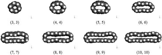 |
| | Fig. 3 Snapshots of the shape of different pristine CNTs on Fe (1 0 0) surface after simulations. | |
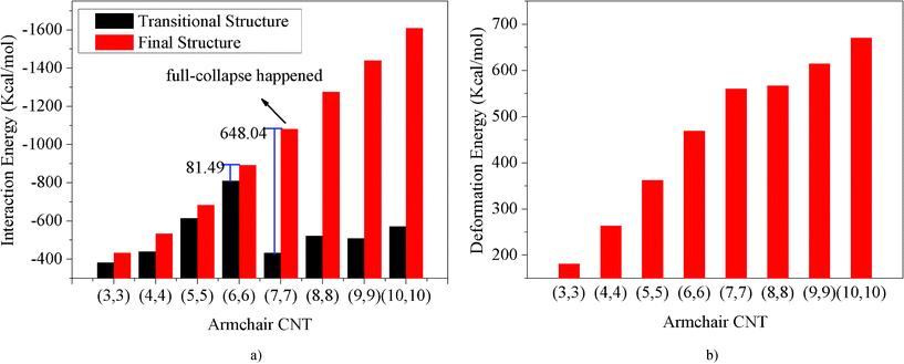 |
| | Fig. 4 The interaction energies of pristine CNT–Fe (1 0 0) systems and deformation energies of pristine CNTs change with CNT diameter. | |
The snapshots of the CNT approaching the Fe surface spontaneously, shown in Fig. 5, show that the CNT approach and collapse happen subsequently. In the initial stage, the CNT–Fe interaction makes the CNT approach the Fe surface, and the cross section of the CNT stretches from a circle (0 ps) to an oval (9 ps) along the normal direction of the plane, trying to contact the Fe surface. Once the bottom of the CNT reaches the Fe surface, the inter-wall interaction (π–π interaction) becomes the main force to induce the CNT to collapse, and the CNT rapidly transforms into a linked double graphitic layer parallel to the plane, like a ribbon on top of the Fe surface (23 ps).
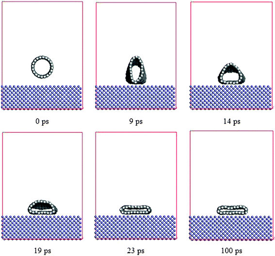 |
| | Fig. 5 Simulation snapshots of the approach and collapse of the CNT (10, 10) on the Fe surface at 0, 9, 14, 19, 23 and 100 ps, respectively. | |
The geometric deformation of the collapsed CNT, characterized by the concentration profiles of the initial CNT and the collapsed CNT, is shown in Fig. 6(a). Here, we manually placed the initial CNT and the collapsed CNT in a box with the same center of mass (COM) and orientation for comparison. Some peak coordinates have been picked out from the concentration profile to reflect the geometric deformation and are shown in Table 1, and Δ denotes the difference between the peak coordinates along the (x, y, z) axis. From Fig. 6(a) and Table 1, we can observe that there is little difference in the concentration profile along the y axis between the initial CNT and the collapsed CNT, which illustrates that there is little deformation along the CNT axial direction. However, the concentration profile along the x axis of the collapsed CNT becomes broad and flat and the concentration profile along the z axis of the collapsed CNT changes from the wide-serration shape to the shape with two arrow peaks. Initially, Δx and Δz are approximately equal, which refers to the circular CNT. After simulation, it is clearly seen from the concentration profile details that the collapsed CNT covering the Fe surface is just like a 18.23 × 36.52 × 3.58 Å3 ribbon. In addition, the geometric configuration of the collapsed CNT on the Fe surface can be further characterized by the intermolecular pair correlation function between the collapsed CNT and the Fe surface. As shown in Fig. 6(b), the distance between the bottom layer of the collapsed CNT and the outermost Fe surface is 2.55 Å, less than the shortest distance of the graphite layer 3.4 Å, which has almost entered the strong adhesive binding region of the chemical bond. It indicates that the interaction between them is very strong. The distance between the opposite walls of the collapsed CNT is 3.4 Å, which is very close to 3.58 Å obtained from the concentration profile. It indicates that it is admissive to analyse the structure of the CNT using the concentration profile.57 Below, the concentration profile is chosen to investigate the structure of the CNTs. The distance 3.4 Å is the same as the shortest distance between the graphite layers 3.4 Å. Such distances have almost entered the strong adhesive binding region of the chemical bond so that we can conclude that the CNT indeed reached complete collapse under the strong interaction between the CNT and the Fe surface. And the interaction energy between the CNT and the Fe surface reached −1623.96 Kcal mol−1. In other words, the adhesion between them is so strong that it is difficult to remove the CNT from the Fe surface again.
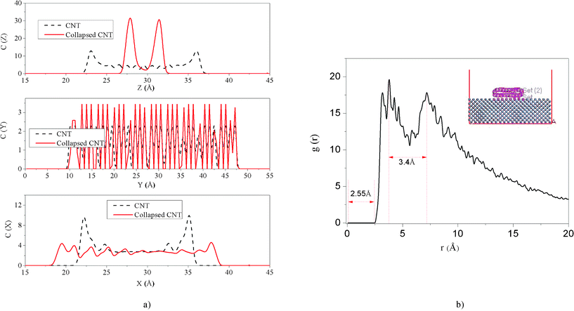 |
| | Fig. 6 (a) Concentration profile of the CNT and the collapsed CNT along the x, y and z axes. The insets are the scheme of CNT and the collapsed CNT placed along the y axis and parallel to the x–y surface with the same COM position in the box. (b) The intermolecular pair correlation function between the Fe surface and the collapsed CNT; the inset is the scheme of the collapsed CNT on the Fe surface. | |
Table 1 Peak details in the concentration profile of CNT (10, 10) and the collapsed CNT (10, 10)
| CNT |
Axis |
First peak (Å) |
Last peak (Å) |
Δ (Å) |
| Initial CNT |
x |
22.12 |
35.15 |
13.02 |
| y |
10.06 |
47.14 |
37.08 |
| z |
22.94 |
36.07 |
13.13 |
| Collapsed CNT |
x |
19.52 |
37.75 |
18.23 |
| y |
10.62 |
47.14 |
36.52 |
| z |
27.99 |
31.57 |
3.58 |
The collapsed CNT ribbon can afford a larger area to cover the Fe surface and the interface adhesion is very strong. Due to the CNT's hydrophobic properties (See ESI Fig. S1 and Video S1†), the collapsed CNTs can isolate the Fe surface from the water solution to inhibit the chemical reaction between them (See ESI Fig. S2†). Therefore, the CNTs adhered onto the Fe surface have potential applications in corrosion protection and scale inhibition fields.
III.II The stability of functionalized CNTs
The intrinsic CNTs with large diameters can easily deform and collapse under certain external forces, such as vdW force,58 electron beam pressure,21 and hydrostatic pressure.23 And the properties of the CNTs can be dramatically affected by the collapse. But sometimes the hollow structure of CNTs can be widely used for hydrogen storage, nanocontainers, molecular transport, etc. So it is similarly important to avoid CNT collapse. Here, we propose a method to enhance the CNT cylindrical structure stability by means of some simple and functional chemical modifications.
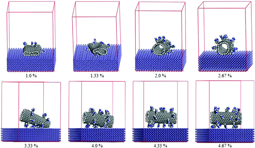 |
| | Fig. 7 Final configurations of the CNTs modified with different numbers of benzimidazole groups on the Fe surface. | |
The chemical modification of the CNTs has been performed by attaching functional groups to the CNT surface through chemical covalent bonding, and the functional groups are randomly end-grafted to the surface of the CNTs. Fig. 7 shows the final configurations of the benzimidazole randomly modified CNTs with different amounts of modification (1.0%, 1.33%, 2.0%, 2.67%, 3.33%, 4.0%, 4.33%, 4.67%) on the Fe surface after simulations. As the modification amount reaches 1.0%, the functionalized CNT collapses onto the Fe surface completely, which is consistent with the results obtained from the intrinsic CNTs. However, the time that the CNT needs to completely collapse increases. By further increasing the modification amount up to 4.0%, all of the modified CNTs collapse partially after 500 ps and behave stably on the Fe surface in the shape shown in Fig. 7. Surprisingly, the CNTs with 4.33% and 4.67% benzimidazole coverage cannot fully collapse, and their structure can maintain the cylindrical shape with slight deformation. Fig. 8 plots the change in interaction energy between the benzimidazole modified CNT and the Fe surface with different amounts of modification. It shows that the interaction energy gets weaker with increasing benzimidazole group surface coverage, which strongly indicates that the modification increases the distance between the CNTs and the Fe surface, thus weakening the influence of the external force on the CNTs (in the described system, the Fe surface is viewed as the external force), so that the small modification, 4.33% benzimidazole coverage, is already sufficient for maintaining the cylindrical structure of CNTs in our described systems. Similarly, CNTs with different amounts of PVA and PAA are also simulated on the Fe surface by changing the functional group coverage (1.0%, 1.33%, 2.0%, 2.67%, 3.33%, 4.0%, 4.33%, 4.67%) on the CNTs. The interaction energies between the Fe surface and the CNTs modified by three kinds of functional groups are plotted in Fig. 9. Broadly speaking, the interaction energies decrease with increasing functional group coverage when the CNT is modified by benzimidazole or PVA. When the CNT is modified by PAA, the interaction energy firstly has a decreasing trend with increasing functional group coverage. And then, when the amount of modification is more than 4.33%, the interaction energies keep a relatively stable state. So we conclude that a little chemical modification can slow down the CNT collapsing process, and sufficient chemical modification can completely avoid the collapse of CNTs. To assess this conclusion further, the distance d1, which expresses the distance between the bottom layer of the collapsed CNT and the outmost Fe surface, obtained from the concentration profile of the final-stage modified CNTs and Fe surface system, is shown in Table 2. From the data of Table 2, we can observe that d1 is about 3 Å before the amount of coverage reaches 4.33%; this is consistent with the results obtained from the intrinsic CNT and Fe surface system. The results demonstrate that the slightly functionalized CNTs collapse onto the Fe surface to some extent. When the coverage is equal to or more than 4.33%, d1 increases dramatically to a larger value. This indicates that sufficient modification increases the distance between the CNTs and the Fe surface, and the collapse of the CNTs can be avoided. It is suggested that surface modification of CNTs not only introduces new functionality, but also effectively enhances the structural stability. Therefore, CNTs randomly modified by appropriate organic inhibitor groups can maintain their cylindrical structures, which have the potential to be used as nanocontainers for maintaining or transporting molecules, etc. In addition, our findings have great practical significance, and CNTs modified by the organic inhibitor groups can be considered to be environmentally-friendly corrosion inhibitors, which can provide some guidance towards understanding corrosion resistance of CNT-inhibitor composites.
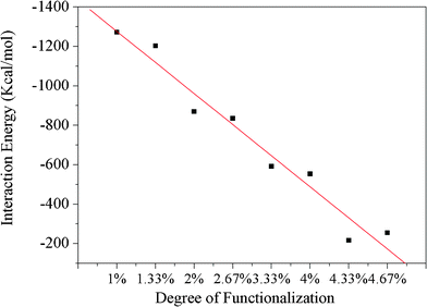 |
| | Fig. 8 Interaction energies between the Fe surface and a benzimidazole modified CNT with different amounts of modification. | |
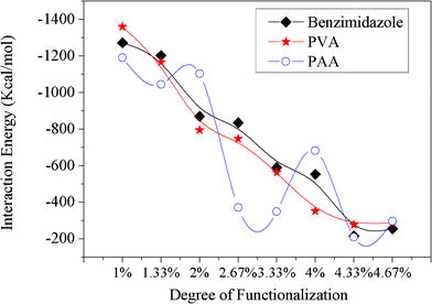 |
| | Fig. 9 Interaction energies between the Fe surface and CNTs modified by three kinds of functional groups with different amounts of modification. | |
Table 2 The distance (d1) between the outmost Fe surface and the bottom layer of the collapsed CNT with modification amounts of 1.0%, 1.33%, 2.0%, 2.67%, 3.33%, 4.0%, 4.33%, and 4.67% for three functional groups, respectively
| Coverage (%) |
1.0 |
1.33 |
2.0 |
2.67 |
3.33 |
4.0 |
4.33 |
4.67 |
| |
d1 (Å) |
| benzimidazole |
2.86 |
2.92 |
2.75 |
N/A |
2.72 |
2.65 |
8.04 |
6.97 |
| PVA |
3.00 |
N/A |
N/A |
N/A |
2.99 |
2.99 |
7.05 |
N/A |
| PAA |
3.00 |
3.02 |
3.02 |
N/A |
6.00 |
2.59 |
N/A |
8.06 |
Conclusions
In summary, we studied the collapse and stability of CNTs functionalized by corrosion inhibitor molecules on the Fe (1 0 0) surface using MM and MD simulations. We found that when the CNT diameter exceeds a certain threshold, the pristine CNTs approach the Fe surface and then collapse spontaneously onto it due to the vdW force between them. Due to the hydrophobic properties of the CNTs, the pristine CNTs collapsed on the Fe surface can isolate the Fe surface from a water solution, suggesting that they have potential applications in corrosion protection and scale inhibition fields. To avoid collapse of CNTs, three kinds of corrosion inhibitor groups are side-grafted onto the CNT surfaces. The results show that some chemical modification can slow down the CNT collapse process, and sufficient chemical modification can effectively avoid the collapse of CNTs. When the modification coverage exceeds 4.33%, three modified CNTs can basically maintain the cylindrical structure on the Fe surface. This study provides an effective and simple way to avoid CNT collapse. In addition, the CNTs randomly modified by appropriate inhibitor groups, with stable structural properties, show great potential for use as nanocontainers for biomolecule transportation, drug delivery, hydrogen storage, etc. Moreover, our findings have great practical significance and CNTs modified by the organic inhibitor groups can be considered to be environmentally-friendly corrosion inhibitors, which can provide some guidance towards understanding corrosion resistance of CNT-inhibitor composites.
Acknowledgements
This work was supported by the National Natural Science Foundation of China (10974258), the Program for New Century Excellent Talents in University (NCET-08-0844), and the Natural Science Foundation of Shandong Province (ZR2010AL009).
References
- S. Iijima, Nature, 1991, 354, 56–58 CrossRef CAS.
- Y. Cheng, G. R. Liu, Z. R. Li and C. Lu, Phys. A, 2006, 367, 293–304 CrossRef CAS.
- Q. B. Zheng, Q. Z. Xue, K. Y. Yan, L. Z. Hao, Q. Li and X. L. Gao, J. Phys. Chem. C, 2007, 111, 4628–4635 CAS.
- P. M. Ajayan, L. S. Schadler, C. Giannaris and A. Rubio, Adv. Mater., 2000, 12, 750–753 CrossRef CAS.
- M. Cadek, J. N. Coleman, V. Barron, K. Hedicke and W. J. Blau, Appl. Phys. Lett., 2002, 81, 5123–5125 CrossRef CAS.
- A. B. Dalton, S. Collins, E. Munoz, J. M. Razal, V. H. Ebron, J. P. Ferraris, J. N. Coleman and B. G. Baughman, Nature, 2003, 423, 703–703 CrossRef CAS.
- M. Cadek, J. N. Coleman, K. P. Ryan, V. Nicolosi, G. Bister, A. Fonseca, J. B. Nagy, K. Szostak, F. Beguin and W. J. Blau, Nano Lett., 2004, 4, 353–356 CrossRef CAS.
- K. Y. Yan, Q. Z. Xue, Q. B. Zheng and L. Z. Hao, Nanotechnology, 2007, 18, 255705 CrossRef.
- B. Kim, J. Lee and I. Yu, J. Appl. Phys., 2003, 94, 6724–6728 CrossRef CAS.
- R. Ramasubramanjam, J. Chen and H. Y. Liu, Appl. Phys. Lett., 2003, 83, 2928–2930 CrossRef.
- J. K. W. Sandler, J. E. Kirk, I. A. Kinloch, M. S. P. Shaffer and A. H. Windle, Polymer, 2003, 44, 5893–5899 CrossRef CAS.
- T. C. Clancy and T. S. Gates, Polymer, 2006, 47, 5990–5996 CrossRef CAS.
- C. Wei, D. Srivastava and K. Cho, Nano Lett., 2002, 2, 647–650 CrossRef CAS.
- E. Kymakis and G. A. J. Amaratunga, Appl. Phys. Lett., 2002, 80, 112–115 CrossRef CAS.
- N. G. Chopra, L. X. Benedict, V. H. Crespi, M. L. Cohen, S. G. Louie and A. Zettl, Nature, 1995, 377, 135–138 CrossRef CAS.
- J. A. Elliott, J. K. W. Sandler, A. H. Windle, R. J. Young and M. S. P. Shaffer, Phys. Rev. Lett., 2004, 92, 095501 CrossRef.
- X. Y. Li, W. Yang and B. Liu, Phys. Rev. Lett., 2007, 98, 205502 CrossRef.
- X. Yang, G. Wu and J. Dong, Appl. Phys. Lett., 2006, 89, 113101 CrossRef.
- B. Liu, M. F. Yu and Y. G. Huang, Phys. Rev. B, 2004, 70, 161402 CrossRef.
- O. Lourie, D. M. Cox and H. D. Wagner, Phys. Rev. Lett., 1998, 81, 1638–1641 CrossRef CAS.
- N. G. Chopra, F. M. Ross and A. Zettl, Chem. Phys. Lett., 1996, 256, 241–245 CrossRef CAS.
- H. R. Gutierrez, U. J. Kim, J. P. Kim and P. C. Eklund, Nano Lett., 2005, 5, 2195–2201 CrossRef CAS.
- P. Tangney, R. B. Capaz, C. D. Spataru, M. L. Cohen and S. G. Louie, Nano Lett., 2005, 5, 2268–2273 CrossRef CAS.
- J. Zang, A. Treibergs, Y. Han and F. Liu, Phys. Rev. Lett., 2004, 92, 105501 CrossRef.
- K. Y. Yan, Q. Z. Xue, Q. B. Zheng, D. Xia, H. J. Chen and J. Xie, J. Phys. Chem. C, 2009, 113, 3120–3126 CAS.
- S. M. Lee and Y. H. Lee, Appl. Phys. Lett., 2000, 76, 2877–2879 CrossRef CAS.
- A. C. Dillon, K. M. Jones, T. A. Bekkedahl, C. H. Kiang, D. S. Bethune and M. J. Heben, Nature, 1997, 386, 377–379 CrossRef CAS.
- T. Takenobu, T. Takano, M. Shiraishi, Y. Murakami, M. Ata, H. Kataura, Y. Achiba and Y. Iwasa, Nat. Mater., 2003, 2, 683–688 CrossRef CAS.
- H. Shiozawa, T. Pichler, A. Gruneis, R. Pfeiffer, H. Kuzmany, Z. Liu, K. Suenaga and H. Kataura, Adv. Mater., 2008, 20, 1443–1449 CrossRef CAS.
- K. Yanagi, Y. Miyata and H. Kataura, Adv. Mater., 2006, 18, 437–441 CrossRef CAS.
- Z. Insepov, D. Wolf and A. Hassanein, Nano Lett., 2006, 6, 1893–1895 CrossRef CAS.
- M. Whitby, L. Cagnon, M. Thanou and N. Quirke, Nano Lett., 2008, 8, 2632–2637 CrossRef CAS.
- M. J. Longhurst and N. Quirke, Nano Lett., 2007, 7, 3324–3328 CrossRef CAS.
- V. Georgakilas, A. Bourlinos, D. Gournis, T. Tsoufis, C. Trapalis, A. Mateo-Alonso and M. Prato, J. Am. Chem. Soc., 2008, 130, 8733–8740 CrossRef CAS.
- Y. Lin, B. Zhou, K. A. S. Fernando, P. Liu, L. F. Allard and Y. P. Sun, Macromolecules, 2003, 36, 7199–7204 CrossRef CAS.
- W. W. Li and C. Gao, Langmuir, 2007, 23, 4575–4582 CrossRef CAS.
- M. S. P. Shaffer and A. H. Windle, Adv. Mater., 1999, 11, 937–941 CrossRef CAS.
- M. Cadek, J. N. Coleman, V. Barron, K. Hedicke and W. J. Blau, Appl. Phys. Lett., 2002, 81, 5123–5125 CrossRef CAS.
- X. F. Zhang, T. Liu, T. V. Sreekumar, S. Kumar, V. C. Moore, R. H. Hauge and R. E. Smalley, Nano Lett., 2003, 3, 1285–1288 CrossRef CAS.
- J. N. Coleman, M. Cadek, R. Blake, V. Nicolosi, K. P. Ryan, C. Belton, A. Fonseca, J. B. Nagy, Y. K. Gun'ko and W. J. Blau, Adv. Funct. Mater., 2004, 14, 791–798 CrossRef CAS.
- O. Probst, E. M. Moore, D. E. Resasco and B. P. Grady, Polymer, 2004, 45, 4437–4443 CrossRef CAS.
- X. F. Zhang, T. Liu, T. V. Sreekumar, S. Kumar, X. D. Hu and K. Smith, Polymer, 2004, 45, 8801–8807 CrossRef CAS.
- L. Q. Liu, A. H. Barber, S. Nuriel and H. D. Wagner, Adv. Funct. Mater., 2005, 15, 975–980 CrossRef CAS.
- J. Xie, Q. Z. Xue, K. Y. Yan, H. J. Chen, D. Xia and M. D. Dong, J. Phys. Chem. C, 2009, 113, 14747–14752 CAS.
- H. Sun, J. Phys. Chem. B, 1998, 102, 7338–7364 CrossRef CAS.
- Q. Wang, W. H. Duan, K. M. Liew and X. Q. He, Appl. Phys. Lett., 2007, 90, 033110 CrossRef.
- Q. Wang, Nano Lett., 2009, 9, 245–249 CrossRef CAS.
- H. C. Andersen, J. Chem. Phys., 1980, 72, 2384–2393 CrossRef CAS.
- Y. L. Liu and W. H. Chen, Macromolecules, 2007, 40, 8881–8886 CrossRef CAS.
- J. M. Haremza, M. A. Hahn, T. D. Krauss, S. Chen and J. Calcines, Nano Lett., 2002, 2, 1253–1258 CrossRef CAS.
- M. Vlope and F. Cleri, Chem. Phys. Lett., 2003, 371, 476–482 CrossRef.
- B. Prathab, V. Subramanian and T. M. Aminabhavi, Polymer, 2007, 48, 409–416 CrossRef CAS.
- M. Grujicic, G. Cao and W. N. Roy, Appl. Surf. Sci., 2004, 227, 349–363 CrossRef CAS.
- J. S. Yang, C. L. Yang, M. S. Wang, B. D. Chen and X. G. Ma, RSC Adv., 2012, 2, 2836–2841 RSC.
- E. E. Oguzie, Y. Li, S. G. Wang and F. Wang, RSC Adv., 2011, 1, 866–873 RSC.
- M. Al-Haik and M. Y. Hussaini, J. Appl. Phys., 2005, 97, 074306 CrossRef.
- Y. Jiang, H. Li, Y. Li, H. Yu, K. M. Liew, Y. He and X. Liu, ACS Nano, 2011, 5, 2126–2133 CrossRef CAS.
- T. Hertel, R. E. Walkup and P. Avouris, Phys. Rev. B, 1998, 58, 13870–13873 CrossRef CAS.
|
| This journal is © The Royal Society of Chemistry 2012 |
Click here to see how this site uses Cookies. View our privacy policy here. 


